EP0353042B1 - Axial field electrical generator - Google Patents
Axial field electrical generator Download PDFInfo
- Publication number
- EP0353042B1 EP0353042B1 EP89307584A EP89307584A EP0353042B1 EP 0353042 B1 EP0353042 B1 EP 0353042B1 EP 89307584 A EP89307584 A EP 89307584A EP 89307584 A EP89307584 A EP 89307584A EP 0353042 B1 EP0353042 B1 EP 0353042B1
- Authority
- EP
- European Patent Office
- Prior art keywords
- hub
- magnets
- hoop
- rotor
- assembly
- Prior art date
- Legal status (The legal status is an assumption and is not a legal conclusion. Google has not performed a legal analysis and makes no representation as to the accuracy of the status listed.)
- Expired - Lifetime
Links
Images


Classifications
-
- H—ELECTRICITY
- H02—GENERATION; CONVERSION OR DISTRIBUTION OF ELECTRIC POWER
- H02K—DYNAMO-ELECTRIC MACHINES
- H02K1/00—Details of the magnetic circuit
- H02K1/06—Details of the magnetic circuit characterised by the shape, form or construction
- H02K1/22—Rotating parts of the magnetic circuit
- H02K1/27—Rotor cores with permanent magnets
- H02K1/2793—Rotors axially facing stators
- H02K1/2795—Rotors axially facing stators the rotor consisting of two or more circumferentially positioned magnets
- H02K1/2796—Rotors axially facing stators the rotor consisting of two or more circumferentially positioned magnets where both axial sides of the rotor face a stator
-
- H—ELECTRICITY
- H02—GENERATION; CONVERSION OR DISTRIBUTION OF ELECTRIC POWER
- H02K—DYNAMO-ELECTRIC MACHINES
- H02K1/00—Details of the magnetic circuit
- H02K1/06—Details of the magnetic circuit characterised by the shape, form or construction
- H02K1/22—Rotating parts of the magnetic circuit
- H02K1/27—Rotor cores with permanent magnets
- H02K1/2793—Rotors axially facing stators
- H02K1/2795—Rotors axially facing stators the rotor consisting of two or more circumferentially positioned magnets
- H02K1/2798—Rotors axially facing stators the rotor consisting of two or more circumferentially positioned magnets where both axial sides of the stator face a rotor
-
- H—ELECTRICITY
- H02—GENERATION; CONVERSION OR DISTRIBUTION OF ELECTRIC POWER
- H02K—DYNAMO-ELECTRIC MACHINES
- H02K15/00—Methods or apparatus specially adapted for manufacturing, assembling, maintaining or repairing of dynamo-electric machines
- H02K15/02—Methods or apparatus specially adapted for manufacturing, assembling, maintaining or repairing of dynamo-electric machines of stator or rotor bodies
- H02K15/03—Methods or apparatus specially adapted for manufacturing, assembling, maintaining or repairing of dynamo-electric machines of stator or rotor bodies having permanent magnets
-
- H—ELECTRICITY
- H02—GENERATION; CONVERSION OR DISTRIBUTION OF ELECTRIC POWER
- H02K—DYNAMO-ELECTRIC MACHINES
- H02K21/00—Synchronous motors having permanent magnets; Synchronous generators having permanent magnets
- H02K21/12—Synchronous motors having permanent magnets; Synchronous generators having permanent magnets with stationary armatures and rotating magnets
- H02K21/24—Synchronous motors having permanent magnets; Synchronous generators having permanent magnets with stationary armatures and rotating magnets with magnets axially facing the armatures, e.g. hub-type cycle dynamos
Definitions
- the invention relates to axial field electrical generator.
- An object of the invention is to provide a compact electrical generator and, in particular, a high speed alternator which can be coupled directly to the shaft of a gas turbine engine and spin at very high speed.
- New magnetic materials for example, cobalt samarium and neodymium boron iron are capable of producing the intense magnetic fields necessary for the generation of substantial levels of electrical power from relatively small generators.
- Generators of this type can be used as primary or auxiliary power systems where compact size and low weight are essential considerations. For instance, they can be used in aircraft as ground run auxiliary power units or they may be useful as standby power generators.
- a brushless synchronous machine of this type having a disc rotor and axial air gap is known from UK Patent Application GB 2,174,252A. There is described therein a machine having a disc rotor made up of six permanent magnet segments uniformly distributed around the rotor. The magnets are embedded between two reinforcing layers of glass fibre reinforced plastic or non-magnetic steel which form the axial faces of the rotor. To absorb centrifugal forces, the disc rotor is bandaged around its periphery with a binding of high-strength material such as several layers of pretensioned glass rovings.
- the machine described is intended for use a either a motor or as a motor vehicle generator. Therefore, it is designed for relatively much lower rotational speeds than the present invention.
- the maximum rotational speed is of the order of less than 10,000 rpm whereas the invention is intended for use at speeds up to ten times greater than this. Consequently, the forces acting on the magnet segments are not exceptionally high and are easily contained by the rotor construction described.
- the glass roving bandage of the known machine will be inadequate to contain the centrifugal forces acting on the segments. As a result the segments will be forced away from the central hub, so that they re restrained only by the side layers and the peripheral bandage. Furthermore the glass rovings of this bandage would almost certainly lack sufficient strength to withstand the centrifugal forces indefinitely.
- the present invention is intended to remedy these deficiencies by providing a rotary disc configuration inherently capable of sustained operation at rotational speeds up to 100,000 rpm.
- the hub is formed with a plurality of radiating means in the form of a series of notches or pockets which receive the permanent magnets and which in the preferred embodiment conform to the shape of the permanent magnets.
- the hoop means encompassing the hub and magnet assembly may comprise a composite assembly consisting of, for example an inner aluminium ring and an outer ring of woven carbon fibre material.
- the hoop means is prestressed sufficiently to resist the normal maximum centrifugal forces experienced by the rotor components.
- the rings may be stressed initially during assembly by forcedly fitting a slightly oversize boss into a centre bore in the hub or by differentially expanding the hub and the hoop means sufficiently to provide a substantially push fit.
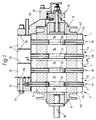
- this shows an axial field alternator having permanent magnet disc rotors 2 shown in greater detail in figs 2 and 3, which are designed to spin at very high rotational speeds.
- the disc rotors 2 are supported for rotation with respect to stators 4.
- the alternator has at least one rotor and at least one stator.
- the illustrated arrangement as depicted has five rotors and interdigitated between these four stators.
- Each rotor 2 carries a plurality of permanent magnets 6 and at either end of the machine abutting the outermost end faces of the permanent magnets are keeper discs 8 formed of magnetically permeable material.
- the two keeper discs 6 provide closed flux paths between magnets in the end rotors.
- the keeper discs 8 are arranged to rotate in unison with the rotors 2 thereby maintaining a constant magnetic field and avoiding hysteresis effects and the eddy current losses associated with fixed means.
- the rotor assembly is mounted on a driving shaft 10 which may be coupled to the output shaft of a prime mover (not shown).
- shaft 10 may be directly coupled to the shaft of a gas turbine engine, the rotational speeds for which this alternator rotor are designed are therefore of the order of up to 100,000 rpm.
- the alternator could be designed as an integral part of a gas turbine engine, for example, the compressor.
- the alternator may be driven by a shaft carried by a free turbine stage which is in turn driven by a gas generator.
- the rotor assembly is supported by bearings one of which is indicated generally at 12 within a housing a portion 14 of which is shown in the drawing. The remainder of the housing and a shaft bearing at the opposite side of the rotor assembly have been omitted for clarity. Because of the high rotational speeds involved the rotor assembly is preferably supported on air bearings, although the illustrated example has rolling element bearings which may be suitable as an alternative depending upon the speeds to be reached. Floating bush type bearings could also be suitable for some installations.
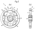
- Fig 2 shows at (a) an end view of a permanent magnet rotor and at (b) a diametric section through the rotor.
- the rotor 2 comprises a hub 16 formed from a single block of aluminium in the shape of an eight-pointed star.
- the eight limbs or ears 18 of the star form between them notches or pockets into which are received the eight permanent magnets of the rotor stage.
- Adjoining faces 20 and 22 of adjacent ears 18 are formed with an included angle which is substantially a right angle. The included corner so formed is radiused to avoid a sharp angle which could concentrate stress in that region.
- the permanent magnets 6 in plan view are roughly triangular and each has a right angled corner which is radiused like the included angle in the hub.
- the dimensions of the magnets 6 correspond to the dimensions of the pockets in the hub so that each magnet may be received into a pocket.
- the height of each magnet is slightly greater than the radial depth of a pocket so that when all eight magnets are assembled onto a hub their outer peripheral faces 23 stand clear of the ends of the ears 18 of the hub. These peripheral faces 23 are curved in accordance with the circumference of a circle of the same diameter.
- the inner diameter of the hoop means 24 is approximately the same as or slightly less the diameter of the circumference of the outer faces of the assembled magnets 6, according to whether the hoop means 24 is to be a push-fit or an interference fit.
- the hoop means 24 preferably comprises a composite assembly consisting of an inner one-piece aluminium ring 26 and an outer carbon fibre resin-impregnated ring 28.
- the aluminium ring 26 in the final rotor assembly is subject to radial compression to maintain at all rotor speeds up to maximum a compressive load on the outer faces of the magnets 6 in opposition to the centrifugal forces imported by rotation.
- the hoop tension needed to generate the compressive forces which hold the magnets onto the hub is provided mainly by the carbon fibre ring.
- the aluminium ring 26 is also effective as a damping means to damp-out oscillations or resonances to which the magnets may be subject.
- the aluminium ring provides a soft bedding between the magnets and the carbon fibre ring, local yielding reduces stress concentrations caused by the corners of the magnets.
- the compressive forces maintain positive location of the magnets against the angled faces 20 and 22.
- the faces 20 and 22 on the hub ears are preferably formed slightly convex so that the contact area is away from the corners of the magnets.
- the hub faces 20 and 22 may be formed flat with the faces of the magnets convex. A combination of the features could also be used if desired.
- the hub 36 is formed from a single block of aluminium in the shape of an octagonal member of short axial length.
- Each of its eight outer faces 40 which receives a magnet segment 38, has a flat surface bounded on both edges adjacent the neighbouring sides by an axially extending locating rib 42.
- the magnet segments 38 In the transverse plane, the magnet segments 38 each have a corresponding flat inner face, a curved outer face and radial sides.
- the dimensions of the inner face of a segment are equal to the dimensions of the flat faces 40 of the hub, while the radius of curvature of the outer face is such that when the segments are mounted on the hub the outer faces lie on the same surface of revolution.
- the raised ribs 42 locate the generally radial side faces of the magnet segments, and the narrow gap between adjacent segments is filled, e.g. with an epoxy filler, to prevent relative movement of the magnets.
- the hub and magnets of the rotors of fig 2 and 3 all have the same axial length and perpendicular end faces. To ensure that all stages have perfectly flat and perpendicular end faces they may be machined after assembly. Balancing is carried out by drilling into the aluminium ribs 42 or ears 16 as appropriate and filling with a denser material for example lead or steel.
- the magnets 38 are mounted on each hub with their magnetic vectors in alternate directions and are held in position by means of circumferential hoops 26 and 28.
- Two such hoops are used in the examples described, one a non-magnetic hoop of aluminium and the other of carbon fibre.
- the inner one 26 of the two hoops is formed of aluminium to be a push-fit onto the stationary magnet/hub assembly at normal room temperatures.
- the composite ring is made either of filament wound carbon fibre or pre-impregnated uni-directional carbon fibre sheet.
- Other composite materials such as KEVLAR (Registered Trade Mark), ceramic fibre etc may also be employed where the strength required is compatible with the material.
- the carbon fibre ring 28 is made beforehand as a push-fit over the aluminium ring 26. The hub, magnet and tension rings can thus be assembled easily. Finally each rotor stage is pre-stressed by forcedly expanding the hub so that the hoops 26 and 28 are placed in tension, thereby to exert a radially inward compressive force on the magnetic segments.
- Hub expansion is maintained by pressing a slightly oversize boss or plug 48 into the central bore of the hub.
- the plug may be simply pressed into position using a straightforward clamping press.
- an oil injection method may be employed in which oil is used as both a lubricant during insertion and as an hydraulic pressure medium to force the plug into the hub.
- the plug in its preferred form as shown in Figure 1 and in Figure 2(b) projects slightly at each side of the rotor. Complementary parts on adjacent rotors co-operate to form the spacer 32.
- the central bore in the hub can be formed in a slight taper and a correspondingly tapered elongate plug pressed into the bore until the required expansion is achieved.
- the surplus length of plug is then machined from both sides to provide flush rotor faces.
- a straight sided plug can also be fitted, into a straight sided bore.
- a succession of progressively larger tapered mandrills is pressed into the hub again until the required expansion is achieved.
- a plug of the appropriate size and already cut to the appropriate length is then pressed into the bore following the last mandrill. This method is more economical of material and the mandrills can be used over and over again.
- the pre-stressed hoop means may be tensioned and fitted to the hub and magnet rotor assembly by hydraulically expanding the carbon fibre reinforced hoop.
- the composite hoop assembly is made up separately with internal dimensions which consitute an interference fit on the hub assembly.
- Hydraulic pressure is then applied to expand the hoop, as the hoop means expands the whole hub assembly can be slipped into the carbon fibre hoop.
- the axial bore of the rotor is formed on a true centre after assembly and the whole is then preferably dynamically balanced.
- the several rotary stages are then assembled together on a common shaft with the flush end face of the hub and plug of one stage abutting the opposite face of the flanged portion of the adjacent rotor stage.
- Means may be provided at either end of the rotor assembly to maintain axial compression.
- Individual rotor stages are keyed one to another by drive pins 58 inserted through axially extending holes formed through the flanges of the expansion plugs and through the hubs.
- the pins 58 are restrained from axial movement by abutment with flanged portions 60 and 62 of end caps 8.
- the shaft 10 and the rotors 2 may be engaged by means of splines or other suitable coupling means.
- the rotors are spaced apart by a narrow gap and generator windings 64 - 70 are interdigitated with the rotor stages.
- the windings can be formed of fine gauge wire wound onto a former in single phase or multi-phase arrangement, generally a three phase output is required from machines of this kind.
- the winding loops instead of comprising the familiar many turns of a single strand of wire are formed of a few turns of bundles of wire consisting of many strands of fine gauge wire.
- the fine gauge minimises eddy current losses in the wire itself.
- the bundles are twisted for just a few twists in each radial limb of a winding to obviate the formation of eddy current loops within the wire bundles.
- These stationary generator windings are generally annular or toroidal in shape and encircle the spacer members of the rotor stages.
- the windings are relatively narrow, that is they are thin in the axial direction, basically to fit into the relatively narrow gaps between the rotor stages.
- the spacing between the rotor stages is dictated principally by the requirements for containing the axial magnetic field created by the magnets. If the gap is too large the output of the generator will fall as the flux density of the inter-stage field falls in the region swept by the stator windings.
- the multi-filament stator windings are supported at their circumferences by a plurality of supporting studs, such as at 74, spaced apart circumferentially around the axis of the alternator to which the winding formers are attached.
- the studs 74 are cantilevered from the end plate 54.
- the stud mounting flanges 76 of the stator windings are suspended by spacer sleeves 78 to ensure that the correct spacing between stators is maintained at all times.
- Fig 4 contains a substantially diagrammatic illustration of a three-phase multi-stranded wire-wound stator, although for clarity only one phase winding is shown in position.
- the or each winding comprises a length of multi-stranded copper wire each strand of which is separately insulated.
- the wire is wound, either stitched on a former or preferably wound around pegs arranged in concentric circles as in the drawing.
- the winding layout is designed to operate in conjunction with the rotor design of fig 2.
- the winding pegs are disposed in three concentric circles 80, 82 and 84.
- the first circle 80 of pegs at the smallest radius defines the inner periphery of the stator winding. This radius is slightly less than radius of the innermost tips of the magnets 6 of fig 2.
- the radius of the second circle 82 of pegs at the intermediate radius is substantially equal to the radius of the circumference of the magnet assembly, and the third circle 84 has a slightly greater radius.
- Each winding comprises a double layer wave winding each arm of which contains single dog-leg created by the pegs in the two outer circles 82 and 84 selected to support the wire.
- the circumferential width of each loop of the winding is sufficient to embrace a complete magnet end face, that is the instantaneous peak flux cut by each of the winding loops is as nearly as possible equal to the total field of each magnet in order to gain maximum efficiency.
- the shape of the magnets and the shape of the winding loops are therefore chosen with this object in mind.
- the start of one winding phase is indicated at X and proceeds in a first layer in a clockwise direction for eight loops.
- the winding direction is then reversed of a further eight loops in a second layer to terminate at point Y.
- These two layers are displaced circumferentially by the width of one peg spacing.
- the peg spacing is determined by the total number of phase windings, in this case there are three phases so, in total, there are six winding layers.
- the described stator has 2 turns per pole, however, the windings may comprise 1 turn per pole, 3 turns per pole, 4 turns per pole etc depending on the voltage required. The greater the number of turns per pole used the greater is the voltage produced, but the lower is the current.
- the stator winding may be totally encapsulated in an epoxy or curable resin material to provide inherent rigidity.
- an expoxy and ceramic mixture may be used to produce a stiffer and more thermally stable material.
- Means by which the stator can be suspended can be incorporated at this stage.
- the superimposed winding layer may be only partially encapsulated to provide in the completed stator a substantially open weave structure thereby creating internal passage through which cooling air may be allow to diffuse.
- the alternator is built-up in stages from one end by stacking the rotor and stator stages one on top of another so that annular rotor and stator stages are mounted alternately.
- the rotors are mounted with the magnet segments 38 in register and with opposite poles facing one another in order to provide maximum field strength.
- Cooling fluid that is an air supply
- Cooling fluid can be provided to the stator windings 88,90 illustrated in figs 5 and 6 through an air supply connection 85 to a hollow cavity through the centres of the hubs.
- the hubs are pierced by radial cooling passages 86 which allow air to be ejected around the periphery of the stator windings.
- a stator comprises a single layer of windings on an annular former into the body of which are built a plurality of generally radial internal cooling passages 86.
- Fig 6 shows a stator winding constructed using for example an etched or printed circuit formation carried on a rigid reinforced plastic substrate 100 wherein the cooling passages 86 may comprise hollow straws suspended in the reinforcing structure.
- each of the magnets 6 was a discrete magnet. However, in their place an annular magnet may be substituted.
- Comprising a relatively thick walled cylinder of magnetisable material the magnets are formed by selectively magnetising axial regions of the cylindrical wall. As before, the magnets thus formed alternate in polarity so that between each magnetised region is an unmagnetised region equivalent to the arms of Figs 2 and 3.
- This annular magnet is preferably magnetised before final assembly. However, because it is composed of magnetic material it is fairly brittle and cannot be stressed safely although it is stronger in compression. Consequently the inner hub cannot be forcedly expanded in order to place the outer hoops 26 and 28 in tension. Instead the outer hoops themselves must be expanded and then fitted onto the annular magnet. The diameter of the unstressed hoops 26 and 28 must therefore be less than the diameter onto which they are located in order to produce the required residual tension.
- the magnetically permeable keeper discs 8 are preferably formed with a double flange arrangement in which the inner flange 54 abuts the end faces of the magnets 6 in the endmost rotors 2.
- the second or outer flange 56 serves a mechanical function at high rotational speeds by generating an axial force which acts on the inner flange 54 in an inward direction tending to counter an outward axial force found to occur in single flange keeper discs.
- the outward axial force tends to bend a single a flange away from the face of the magnets thereby introducing an unwanted airgap in the magnetic circuit causing a loss of efficiency.
- the opposing force introduced by the second flange maintains contact between the inner face of the inner flange 54 and the outermost faces of the end rotor magnets.
Description
- The invention relates to axial field electrical generator.
- An object of the invention is to provide a compact electrical generator and, in particular, a high speed alternator which can be coupled directly to the shaft of a gas turbine engine and spin at very high speed. New magnetic materials, for example, cobalt samarium and neodymium boron iron are capable of producing the intense magnetic fields necessary for the generation of substantial levels of electrical power from relatively small generators. Generators of this type can be used as primary or auxiliary power systems where compact size and low weight are essential considerations. For instance, they can be used in aircraft as ground run auxiliary power units or they may be useful as standby power generators.
- A brushless synchronous machine of this type having a disc rotor and axial air gap is known from UK Patent Application GB 2,174,252A. There is described therein a machine having a disc rotor made up of six permanent magnet segments uniformly distributed around the rotor. The magnets are embedded between two reinforcing layers of glass fibre reinforced plastic or non-magnetic steel which form the axial faces of the rotor. To absorb centrifugal forces, the disc rotor is bandaged around its periphery with a binding of high-strength material such as several layers of pretensioned glass rovings.
- The machine described is intended for use a either a motor or as a motor vehicle generator. Therefore, it is designed for relatively much lower rotational speeds than the present invention. In a motor vehicle application the maximum rotational speed is of the order of less than 10,000 rpm whereas the invention is intended for use at speeds up to ten times greater than this. Consequently, the forces acting on the magnet segments are not exceptionally high and are easily contained by the rotor construction described.
- At very high rotational speeds of the order of 100,000 rpm the glass roving bandage of the known machine will be inadequate to contain the centrifugal forces acting on the segments. As a result the segments will be forced away from the central hub, so that they re restrained only by the side layers and the peripheral bandage. Furthermore the glass rovings of this bandage would almost certainly lack sufficient strength to withstand the centrifugal forces indefinitely.
- Published European Patent Application 0026584 A1 also concerns a multi-disc electric generator of the type of present interest. The magnet arrays of the generator rotors are mounted in supporting discs, of non-magnetic material, which are rotated by a drive shaft from the turbine stage of a gas turbine engine. However, the generator is intended to run at a design speed of about 13,750 rpm and the design of the rotor is considered unsuitable for operation at the much higher rotational speeds envisaged in the present instance.
- The present invention is intended to remedy these deficiencies by providing a rotary disc configuration inherently capable of sustained operation at rotational speeds up to 100,000 rpm.
- According to one aspect of the invention an axial field electrical generator capable of operating at very high rotational speeds comprises at least one permanent magnet disc rotor in which a plurality of permanent magnet segments are spaced apart around a hub which carries a plurality of limbs forming notches or pockets to receive the permanent magnets, wherein engagement between the magnets and the hub pockets is maintained during operation by means of a hoop of non-magnetic material encompassing the hub and magnets, and a stator winding is spaced a short axial distance from a face of the or each disc rotor characterised in that the hoop means encircling the rotor assembly is permanently stressed by means of a member forcably fitted into a central bore in the central hub during assembly so as to expand the hub and hoop means whereby to install in the hoop means sufficient tensile force to maintain positive engagement between the hub, magnets and hoop means throughout operation of the generator.
- Preferably the hub is formed with a plurality of radiating means in the form of a series of notches or pockets which receive the permanent magnets and which in the preferred embodiment conform to the shape of the permanent magnets.
- The hoop means encompassing the hub and magnet assembly may comprise a composite assembly consisting of, for example an inner aluminium ring and an outer ring of woven carbon fibre material. The hoop means is prestressed sufficiently to resist the normal maximum centrifugal forces experienced by the rotor components. The rings may be stressed initially during assembly by forcedly fitting a slightly oversize boss into a centre bore in the hub or by differentially expanding the hub and the hoop means sufficiently to provide a substantially push fit.
- The invention and how it may be carried out in practice will now be described with reference, by way of example only, to the embodiment illustrated in the accompanying drawings, in which:
- Fig 1 shows a view of an axial section through an axial field disc rotor electrical generator,
- Fig 2 shows a sectional view through a first design of rotor stage on line A-A in the generator of Fig 1, view (a) being transverse to the axis of the rotor and (b) being a lateral view,
- Fig 3 shows a section through a second design of rotor,
- Fig 4 is a schematic view of a wire wound stator showing one phase of a three phase winding,
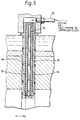
- Fig 5 shows a sectional view of a stator winding having internal cooling passages, and
- Fig 6 is a partly sectioned fragmentary view of an etched winding stator having internal cooling passages.
- Referring to fig 1 this shows an axial field alternator having permanent
magnet disc rotors 2 shown in greater detail in figs 2 and 3, which are designed to spin at very high rotational speeds. - The
disc rotors 2 are supported for rotation with respect tostators 4. As a minimum, and in dependance upon the electrical power output required, the alternator has at least one rotor and at least one stator. The illustrated arrangement as depicted has five rotors and interdigitated between these four stators. Eachrotor 2 carries a plurality ofpermanent magnets 6 and at either end of the machine abutting the outermost end faces of the permanent magnets arekeeper discs 8 formed of magnetically permeable material. The twokeeper discs 6 provide closed flux paths between magnets in the end rotors. Thekeeper discs 8 are arranged to rotate in unison with therotors 2 thereby maintaining a constant magnetic field and avoiding hysteresis effects and the eddy current losses associated with fixed means. - The rotor assembly is mounted on a
driving shaft 10 which may be coupled to the output shaft of a prime mover (not shown). For example,shaft 10 may be directly coupled to the shaft of a gas turbine engine, the rotational speeds for which this alternator rotor are designed are therefore of the order of up to 100,000 rpm. The alternator could be designed as an integral part of a gas turbine engine, for example, the compressor. Optionally the alternator may be driven by a shaft carried by a free turbine stage which is in turn driven by a gas generator. - The rotor assembly is supported by bearings one of which is indicated generally at 12 within a housing a
portion 14 of which is shown in the drawing. The remainder of the housing and a shaft bearing at the opposite side of the rotor assembly have been omitted for clarity. Because of the high rotational speeds involved the rotor assembly is preferably supported on air bearings, although the illustrated example has rolling element bearings which may be suitable as an alternative depending upon the speeds to be reached. Floating bush type bearings could also be suitable for some installations. - Fig 2 shows at (a) an end view of a permanent magnet rotor and at (b) a diametric section through the rotor. Referring particularly to the view of fig 2 (a) the
rotor 2 comprises ahub 16 formed from a single block of aluminium in the shape of an eight-pointed star. The eight limbs orears 18 of the star form between them notches or pockets into which are received the eight permanent magnets of the rotor stage.Adjoining faces adjacent ears 18 are formed with an included angle which is substantially a right angle. The included corner so formed is radiused to avoid a sharp angle which could concentrate stress in that region. - The
permanent magnets 6 in plan view are roughly triangular and each has a right angled corner which is radiused like the included angle in the hub. The dimensions of themagnets 6 correspond to the dimensions of the pockets in the hub so that each magnet may be received into a pocket. The height of each magnet is slightly greater than the radial depth of a pocket so that when all eight magnets are assembled onto a hub their outerperipheral faces 23 stand clear of the ends of theears 18 of the hub. Theseperipheral faces 23 are curved in accordance with the circumference of a circle of the same diameter. - Engagement of the
magnets 6 with the pockets formed between theears 18 of thehub 16 is positively maintained by pre-stressed hoop means 24 encompassing the assembly. The inner diameter of the hoop means 24 is approximately the same as or slightly less the diameter of the circumference of the outer faces of the assembledmagnets 6, according to whether the hoop means 24 is to be a push-fit or an interference fit. - The hoop means 24 preferably comprises a composite assembly consisting of an inner one-
piece aluminium ring 26 and an outer carbon fibre resin-impregnatedring 28. Thealuminium ring 26 in the final rotor assembly is subject to radial compression to maintain at all rotor speeds up to maximum a compressive load on the outer faces of themagnets 6 in opposition to the centrifugal forces imported by rotation. The hoop tension needed to generate the compressive forces which hold the magnets onto the hub is provided mainly by the carbon fibre ring. Thealuminium ring 26 is also effective as a damping means to damp-out oscillations or resonances to which the magnets may be subject. Also the aluminium ring provides a soft bedding between the magnets and the carbon fibre ring, local yielding reduces stress concentrations caused by the corners of the magnets. The compressive forces maintain positive location of the magnets against theangled faces faces - Referring now to fig 3 the
hub 36 is formed from a single block of aluminium in the shape of an octagonal member of short axial length. Each of its eightouter faces 40, which receives amagnet segment 38, has a flat surface bounded on both edges adjacent the neighbouring sides by an axially extending locatingrib 42. In the transverse plane, themagnet segments 38 each have a corresponding flat inner face, a curved outer face and radial sides. The dimensions of the inner face of a segment are equal to the dimensions of the flat faces 40 of the hub, while the radius of curvature of the outer face is such that when the segments are mounted on the hub the outer faces lie on the same surface of revolution. The raisedribs 42 locate the generally radial side faces of the magnet segments, and the narrow gap between adjacent segments is filled, e.g. with an epoxy filler, to prevent relative movement of the magnets. - The hub and magnets of the rotors of fig 2 and 3 all have the same axial length and perpendicular end faces. To ensure that all stages have perfectly flat and perpendicular end faces they may be machined after assembly. Balancing is carried out by drilling into the
aluminium ribs 42 orears 16 as appropriate and filling with a denser material for example lead or steel. - The
magnets 38 are mounted on each hub with their magnetic vectors in alternate directions and are held in position by means ofcircumferential hoops inner one 26 of the two hoops is formed of aluminium to be a push-fit onto the stationary magnet/hub assembly at normal room temperatures. Around the outside of the aluminium hoop there is formed a second hoop of composite material. - Preferably the composite ring is made either of filament wound carbon fibre or pre-impregnated uni-directional carbon fibre sheet. Other composite materials such as KEVLAR (Registered Trade Mark), ceramic fibre etc may also be employed where the strength required is compatible with the material. If the ring is formed in situ and heat curable resin is used care must be taken during the curing process not to exceed the Curie temperature of the magnetic material. Preferably, however, the
carbon fibre ring 28 is made beforehand as a push-fit over thealuminium ring 26. The hub, magnet and tension rings can thus be assembled easily. Finally each rotor stage is pre-stressed by forcedly expanding the hub so that thehoops - Hub expansion is maintained by pressing a slightly oversize boss or plug 48 into the central bore of the hub. The plug may be simply pressed into position using a straightforward clamping press. Alternatively, an oil injection method may be employed in which oil is used as both a lubricant during insertion and as an hydraulic pressure medium to force the plug into the hub. The plug in its preferred form as shown in Figure 1 and in Figure 2(b) projects slightly at each side of the rotor. Complementary parts on adjacent rotors co-operate to form the
spacer 32. - The central bore in the hub can be formed in a slight taper and a correspondingly tapered elongate plug pressed into the bore until the required expansion is achieved. The surplus length of plug is then machined from both sides to provide flush rotor faces. A straight sided plug can also be fitted, into a straight sided bore. In the corresponding method of fitting a succession of progressively larger tapered mandrills is pressed into the hub again until the required expansion is achieved. A plug of the appropriate size and already cut to the appropriate length is then pressed into the bore following the last mandrill. This method is more economical of material and the mandrills can be used over and over again.
- The pre-stressed hoop means may be tensioned and fitted to the hub and magnet rotor assembly by hydraulically expanding the carbon fibre reinforced hoop. The composite hoop assembly is made up separately with internal dimensions which consitute an interference fit on the hub assembly. To enable the hoop means to be fitted to the hub assembly the hoop is positioned in a jig together with the hub assembly including the magnets. Hydraulic pressure is then applied to expand the hoop, as the hoop means expands the whole hub assembly can be slipped into the carbon fibre hoop.
- The axial bore of the rotor is formed on a true centre after assembly and the whole is then preferably dynamically balanced. The several rotary stages are then assembled together on a common shaft with the flush end face of the hub and plug of one stage abutting the opposite face of the flanged portion of the adjacent rotor stage. Means may be provided at either end of the rotor assembly to maintain axial compression.
Individual rotor stages are keyed one to another bydrive pins 58 inserted through axially extending holes formed through the flanges of the expansion plugs and through the hubs. Thepins 58 are restrained from axial movement by abutment withflanged portions end caps 8. Alternatively, theshaft 10 and therotors 2 may be engaged by means of splines or other suitable coupling means. - In the rotor assembly as described and illustrated the rotors are spaced apart by a narrow gap and generator windings 64 - 70 are interdigitated with the rotor stages. The windings can be formed of fine gauge wire wound onto a former in single phase or multi-phase arrangement, generally a three phase output is required from machines of this kind. In the example being described the winding loops instead of comprising the familiar many turns of a single strand of wire are formed of a few turns of bundles of wire consisting of many strands of fine gauge wire. The fine gauge minimises eddy current losses in the wire itself. Also the bundles are twisted for just a few twists in each radial limb of a winding to obviate the formation of eddy current loops within the wire bundles.
- These stationary generator windings are generally annular or toroidal in shape and encircle the spacer members of the rotor stages. In the form illustrated the windings are relatively narrow, that is they are thin in the axial direction, basically to fit into the relatively narrow gaps between the rotor stages. The spacing between the rotor stages is dictated principally by the requirements for containing the axial magnetic field created by the magnets. If the gap is too large the output of the generator will fall as the flux density of the inter-stage field falls in the region swept by the stator windings.
- Similar considerations relating to the behaviour of the magnetic field apply to the alternative arrangement in which the rotor stages abut one another and the generator windings are positioned at either end of the rotor assembly. The windings are again wound on annular formers and are located as close as possible to the exposed end faces of the rotor. As the lines of magnetic flux emerge from these end faces the field has a strongly predominant axial component and providing these end located windings are kept fairly thin, in the axial direction, and close to the end faces of the rotor output losses are kept low.
- The multi-filament stator windings are supported at their circumferences by a plurality of supporting studs, such as at 74, spaced apart circumferentially around the axis of the alternator to which the winding formers are attached. In the particular example illustrated, the
studs 74 are cantilevered from theend plate 54. As shown in the drawing thestud mounting flanges 76 of the stator windings are suspended byspacer sleeves 78 to ensure that the correct spacing between stators is maintained at all times. - Fig 4 contains a substantially diagrammatic illustration of a three-phase multi-stranded wire-wound stator, although for clarity only one phase winding is shown in position. The or each winding comprises a length of multi-stranded copper wire each strand of which is separately insulated. The wire is wound, either stitched on a former or preferably wound around pegs arranged in concentric circles as in the drawing. The winding layout is designed to operate in conjunction with the rotor design of fig 2.
- The winding pegs are disposed in three
concentric circles first circle 80 of pegs at the smallest radius defines the inner periphery of the stator winding. This radius is slightly less than radius of the innermost tips of themagnets 6 of fig 2. - The radius of the
second circle 82 of pegs at the intermediate radius is substantially equal to the radius of the circumference of the magnet assembly, and thethird circle 84 has a slightly greater radius. - Each winding comprises a double layer wave winding each arm of which contains single dog-leg created by the pegs in the two
outer circles - The start of one winding phase is indicated at X and proceeds in a first layer in a clockwise direction for eight loops. The winding direction is then reversed of a further eight loops in a second layer to terminate at point Y. These two layers are displaced circumferentially by the width of one peg spacing. The peg spacing is determined by the total number of phase windings, in this case there are three phases so, in total, there are six winding layers.
- The described stator has 2 turns per pole, however, the windings may comprise 1 turn per pole, 3 turns per pole, 4 turns per pole etc depending on the voltage required. The greater the number of turns per pole used the greater is the voltage produced, but the lower is the current.
- The stator winding may be totally encapsulated in an epoxy or curable resin material to provide inherent rigidity. Alternatively an expoxy and ceramic mixture may be used to produce a stiffer and more thermally stable material. Means by which the stator can be suspended can be incorporated at this stage. Where it is desired to provide internal stator cooling the superimposed winding layer may be only partially encapsulated to provide in the completed stator a substantially open weave structure thereby creating internal passage through which cooling air may be allow to diffuse.
- The alternator is built-up in stages from one end by stacking the rotor and stator stages one on top of another so that annular rotor and stator stages are mounted alternately. The rotors are mounted with the
magnet segments 38 in register and with opposite poles facing one another in order to provide maximum field strength. - Forced induction of cooling air may be provided as necessary, for example, by means of air ducted from a bleed on the compressor section of a gas turbine engine.
Cooling fluid, that is an air supply, can be provided to thestator windings air supply connection 85 to a hollow cavity through the centres of the hubs. The hubs are pierced byradial cooling passages 86 which allow air to be ejected around the periphery of the stator windings. - In one embodiment of the basic design the
formers stator windings internal cooling passages 86 supplied with air from an external supply, see Fig 5. In one arrangement (not shown) a stator comprises a single layer of windings on an annular former into the body of which are built a plurality of generally radialinternal cooling passages 86. Fig 6 shows a stator winding constructed using for example an etched or printed circuit formation carried on a rigid reinforcedplastic substrate 100 wherein thecooling passages 86 may comprise hollow straws suspended in the reinforcing structure. - In all the arrangements described above it was assumed that each of the
magnets 6 was a discrete magnet. However, in their place an annular magnet may be substituted. Comprising a relatively thick walled cylinder of magnetisable material the magnets are formed by selectively magnetising axial regions of the cylindrical wall. As before, the magnets thus formed alternate in polarity so that between each magnetised region is an unmagnetised region equivalent to the arms of Figs 2 and 3. - This annular magnet is preferably magnetised before final assembly. However, because it is composed of magnetic material it is fairly brittle and cannot be stressed safely although it is stronger in compression. Consequently the inner hub cannot be forcedly expanded in order to place the
outer hoops unstressed hoops - The magnetically
permeable keeper discs 8 are preferably formed with a double flange arrangement in which theinner flange 54 abuts the end faces of themagnets 6 in theendmost rotors 2. The second or outer flange 56 serves a mechanical function at high rotational speeds by generating an axial force which acts on theinner flange 54 in an inward direction tending to counter an outward axial force found to occur in single flange keeper discs. The outward axial force tends to bend a single a flange away from the face of the magnets thereby introducing an unwanted airgap in the magnetic circuit causing a loss of efficiency. - The opposing force introduced by the second flange maintains contact between the inner face of the
inner flange 54 and the outermost faces of the end rotor magnets.
Claims (7)
- An axial field electrical generator capable of operating at very high rotational speeds comprises at least one permanent magnet disc rotor (2) in which a plurality of permanent magnet segments (6) are spaced apart around a hub (16) which carries a plurality of limbs (18) forming notches or pockets to receive the permanent magnets (6), wherein engagement between the magnets (6) and the hub pockets is maintained during operation by means of a hoop (24) of non-magnetic material encompassing the hub and magnets, and a stator winding (4) is spaced a short axial distance from a face of the or each disc rotor (6)
characterised in that:
the hoop means (24) encircling the rotor assembly (6) is permanently stressed by means of a member (48) forcably fitted into a central bore in the central hub (16) during assembly so as to expand the hub (16) and hoop means (24) whereby to instal in the hoop means (24) sufficient tensile force to maintain positive engagement between the hub (16), magnets (6) and hoop means (24) throughout operation of the generator. - A generator according to any preceding claim further characterised in that the prestressed hoop means (24) comprises a composite hoop assembly including an inner non-magnetic metal ring (26) and an outer ring of composite material (28).
- A generator as claimed in claim 2 further characterised in that the composite material ring (28) is filament wound carbon fibre or is fabricated using resin impregnated carbon fibre sheet.
- A generator according to any preceding claim further characterised in that the hoop means (24) is formed initially as a push fit and is stressed during assembly with the hub (16) and magnets (6) by expansion of the hub by forcedly fitting into a central bore of the hub (16) a relatively tapered boss (48).
- A generator according to any preceding claim further characterised in that the hoop means (24) is formed as an interference fit to the hub (16) and magnets (6) and assembly is achieved by differential expansion of the hub and the hoop means.
- A generator according to any preceding claim further characterised in that the stator winding (4) comprises a multi-stranded coreless winding at least partially encapsulated to form a rigid self-supporting structure and is suspended by means (76) attached towards its periphery.
- A generator according to any of claims 1 to 6 further characterised in that a substantial portion of the winding structure is unencapsulated so as to constitute an open porous structure through which cooling air may circulate.
Applications Claiming Priority (2)
| Application Number | Priority Date | Filing Date | Title |
|---|---|---|---|
| GB888817760A GB8817760D0 (en) | 1988-07-26 | 1988-07-26 | Electrical power generator |
| GB8817760 | 1988-07-26 |
Publications (2)
| Publication Number | Publication Date |
|---|---|
| EP0353042A1 EP0353042A1 (en) | 1990-01-31 |
| EP0353042B1 true EP0353042B1 (en) | 1994-04-27 |
Family
ID=10641113
Family Applications (1)
| Application Number | Title | Priority Date | Filing Date |
|---|---|---|---|
| EP89307584A Expired - Lifetime EP0353042B1 (en) | 1988-07-26 | 1989-07-26 | Axial field electrical generator |
Country Status (5)
| Country | Link |
|---|---|
| US (1) | US5021698A (en) |
| EP (1) | EP0353042B1 (en) |
| JP (1) | JP2705982B2 (en) |
| DE (1) | DE68914901T2 (en) |
| GB (2) | GB8817760D0 (en) |
Cited By (1)
| Publication number | Priority date | Publication date | Assignee | Title |
|---|---|---|---|---|
| WO2004057738A1 (en) * | 2002-12-20 | 2004-07-08 | Jannali Holdings Pty Ltd | Modularly segmented air core windings electric motor or generator |
Families Citing this family (71)
| Publication number | Priority date | Publication date | Assignee | Title |
|---|---|---|---|---|
| GB2261327B8 (en) * | 1991-11-06 | 2000-02-02 | Turbo Genset Company Ltd | A keeper disc for a rotary electrical machine |
| DE4223831A1 (en) * | 1992-07-20 | 1994-02-03 | Piller Gmbh Co Kg Anton | Electrically excited transverse flow machine |
| US5955809A (en) * | 1992-08-17 | 1999-09-21 | Intellectual Property Law Department Sundstrand Corporation | Permanent magnet generator with auxiliary winding |
| US5309081A (en) * | 1992-08-18 | 1994-05-03 | Sundstrand Corporation | Power conversion system with dual permanent magnet generator having prime mover start capability |
| US5394321A (en) * | 1992-09-02 | 1995-02-28 | Electric Power Research Institute, Inc. | Quasi square-wave back-EMF permanent magnet AC machines with five or more phases |
| GB2278504B (en) * | 1993-05-12 | 1997-04-02 | Imperial College | Rotary electrical machines |
| US5396140A (en) * | 1993-05-28 | 1995-03-07 | Satcon Technology, Corp. | Parallel air gap serial flux A.C. electrical machine |
| GB9313943D0 (en) * | 1993-07-06 | 1993-08-18 | British Nuclear Fuels Plc | Rotors |
| GB9415436D0 (en) * | 1994-07-30 | 1994-09-21 | Provost Michael J | Auxiliary gas turbine engines |
| GB2297870A (en) * | 1995-02-09 | 1996-08-14 | British Nuclear Fuels Plc | An energy storage and conversion apparatus |
| FI112296B (en) * | 1995-03-24 | 2003-11-14 | Kone Corp | Lift motor damping winding |
| GB9510994D0 (en) * | 1995-05-31 | 1995-07-26 | Turbo Genset The Company Ltd | Rotary electrical machines |
| US5760507A (en) * | 1996-02-06 | 1998-06-02 | Ford Global Technologies, Inc. | Electrical generating system for a motor vehicle |
| US6169354B1 (en) | 1996-05-24 | 2001-01-02 | Halo Data Devices, Inc. | Thin film electric motors |
| GB2316812A (en) * | 1996-08-07 | 1998-03-04 | Imperial College | Rotary electric machines having disk rotor retention ring |
| DE69731209D1 (en) | 1996-08-09 | 2004-11-18 | Turbo Genset Co Ltd | ROTATING ELECTRICAL MACHINES |
| US6084319A (en) * | 1996-10-16 | 2000-07-04 | Canon Kabushiki Kaisha | Linear motor, and stage device and exposure apparatus provided with the same |
| US5982074A (en) | 1996-12-11 | 1999-11-09 | Advanced Technologies Int., Ltd. | Axial field motor/generator |
| US5767600A (en) * | 1997-02-27 | 1998-06-16 | Whiteley; Eric | Modular motor |
| US6195869B1 (en) | 1997-08-05 | 2001-03-06 | Turbo Genset Company | Method of applying a retention ring to a disc rotor assembly |
| US6204588B1 (en) | 1999-05-27 | 2001-03-20 | Halo Data Devices, Inc. | Rotor capable of being used as a recording media |
| DE10020860A1 (en) * | 2000-04-28 | 2001-11-15 | Genius Ingenieurgmbh | Electric machine with disc rotors |
| US20040247437A1 (en) * | 2001-10-25 | 2004-12-09 | Ryoichi Otaki | Wind power generator |
| JPWO2004017489A1 (en) * | 2002-08-16 | 2005-12-08 | ヤマハ発動機株式会社 | Saddle riding vehicle |
| US7081696B2 (en) | 2004-08-12 | 2006-07-25 | Exro Technologies Inc. | Polyphasic multi-coil generator |
| US7514833B2 (en) * | 2004-09-03 | 2009-04-07 | Ut-Battelle Llc | Axial gap permanent-magnet machine with reluctance poles and PM element covers |
| JP2006304562A (en) * | 2005-04-25 | 2006-11-02 | Nissan Motor Co Ltd | Rotor structure of axial gap rotating electric machine |
| JP5172090B2 (en) * | 2005-11-22 | 2013-03-27 | 株式会社グローバルエナジー | Multi-head generator |
| AU2007257187A1 (en) | 2006-06-08 | 2007-12-13 | Exro Technologies Inc. | Poly-phasic multi-coil generator |
| CA2549882A1 (en) * | 2006-06-12 | 2007-12-12 | Msi Machineering Solutions Inc. | Axial flux switched reluctance motor |
| US7375449B2 (en) * | 2006-08-17 | 2008-05-20 | Butterfield Paul D | Optimized modular electrical machine using permanent magnets |
| US8558425B2 (en) * | 2006-10-26 | 2013-10-15 | Deere & Company | Motor having stator with generally planar windings |
| KR101420467B1 (en) * | 2007-03-23 | 2014-07-17 | 신에쓰 가가꾸 고교 가부시끼가이샤 | Permanent-magnet generator and windmill generator using the same |
| JP2009072009A (en) | 2007-09-14 | 2009-04-02 | Shin Etsu Chem Co Ltd | Permanent magnet rotating machine |
| US9719428B2 (en) * | 2007-11-30 | 2017-08-01 | United Technologies Corporation | Gas turbine engine with pylon mounted accessory drive |
| US20090205341A1 (en) * | 2008-02-20 | 2009-08-20 | Muldoon Marc J | Gas turbine engine with twin towershaft accessory gearbox |
| US8698367B2 (en) * | 2008-04-17 | 2014-04-15 | Synchrony, Inc. | High-speed permanent magnet motor and generator with low-loss metal rotor |
| KR20110014591A (en) | 2008-04-18 | 2011-02-11 | 신크로니, 아이엔씨. | Magnetic thrust bearing with integrated electronics |
| US20100194251A1 (en) * | 2009-02-02 | 2010-08-05 | Sikes George W | Axial generator for Windcrank™ vertical axis wind turbine |
| US9816441B2 (en) * | 2009-03-30 | 2017-11-14 | United Technologies Corporation | Gas turbine engine with stacked accessory components |
| US7646178B1 (en) | 2009-05-08 | 2010-01-12 | Fradella Richard B | Broad-speed-range generator |
| US9583991B2 (en) * | 2009-06-24 | 2017-02-28 | Synchrony, Inc. | Systems, devices, and/or methods for managing magnetic bearings |
| WO2011163456A1 (en) | 2010-06-23 | 2011-12-29 | Synchrony, Inc. | Split magnetic thrust bearing |
| WO2013032401A1 (en) * | 2011-08-31 | 2013-03-07 | Akribis Systems Pte Ltd | High torque, low inertia direct drive motor |
| EP2842219B1 (en) * | 2012-04-27 | 2017-08-23 | Atlas Copco Airpower N.V. | Method of composing a sleeve assembly for containment purposes in high centrifugal applications |
| WO2014040112A1 (en) * | 2012-09-17 | 2014-03-20 | Guina Research & Development Pty Ltd | Electromagnetic turbine |
| JP6255231B2 (en) * | 2013-12-11 | 2017-12-27 | 株式会社ダイナックス | Axial gap motor |
| US10797573B2 (en) * | 2014-04-16 | 2020-10-06 | Power It Perfect, Inc. | Axial motor/generator having multiple inline stators and rotors with stacked/layered permanent magnets, coils, and a controller |
| US10298104B2 (en) * | 2014-04-16 | 2019-05-21 | Power It Perfect, Inc. | Electrical motor and electrical generator device |
| US10020718B2 (en) * | 2015-05-15 | 2018-07-10 | Saqr Majed Bin Saqr Al Marri | Alternator device |
| FR3037198B1 (en) * | 2015-06-08 | 2018-10-12 | Valeo Equipements Electriques Moteur | ROTOR FOR ROTATING ELECTRIC MACHINE |
| WO2017156135A1 (en) | 2016-03-08 | 2017-09-14 | Ignacio Juarez | Vertical axis wind turbine |
| US10340760B2 (en) * | 2017-01-11 | 2019-07-02 | Infinitum Electric Inc. | System and apparatus for segmented axial field rotary energy device |
| US10186922B2 (en) | 2017-01-11 | 2019-01-22 | Infinitum Electric Inc. | System and apparatus for axial field rotary energy device |
| US11177726B2 (en) | 2017-01-11 | 2021-11-16 | Infinitum Electric, Inc. | System and apparatus for axial field rotary energy device |
| US11081996B2 (en) | 2017-05-23 | 2021-08-03 | Dpm Technologies Inc. | Variable coil configuration system control, apparatus and method |
| PL233865B1 (en) * | 2017-07-28 | 2019-12-31 | Equelo Spólka Z Ograniczona Odpowiedzialnoscia | Electric machine |
| JP6704007B2 (en) * | 2018-03-08 | 2020-06-03 | 三菱重工業株式会社 | motor |
| WO2019190959A1 (en) | 2018-03-26 | 2019-10-03 | Infinitum Electric Inc. | System and apparatus for axial field rotary energy device |
| FR3083023B1 (en) * | 2018-06-22 | 2021-12-03 | Whylot Sas | ROTOR FOR ELECTROMAGNETIC MOTOR OR GENERATOR WITH TAPERED BRANCHES |
| US11664663B2 (en) | 2018-09-12 | 2023-05-30 | Semtive Inc. | Micro inverter and controller |
| FR3086465B1 (en) | 2018-09-24 | 2021-05-21 | Whylot Sas | ROTOR FOR ELECTROMAGNETIC MOTOR OR GENERATOR WITH HUB BODY AND BRANCHES IN COMPOSITE LAYERS WITH DIFFERENT ORIENTATION FIBERS |
| US11722026B2 (en) | 2019-04-23 | 2023-08-08 | Dpm Technologies Inc. | Fault tolerant rotating electric machine |
| US11283319B2 (en) | 2019-11-11 | 2022-03-22 | Infinitum Electric, Inc. | Axial field rotary energy device with PCB stator having interleaved PCBS |
| US20210218304A1 (en) | 2020-01-14 | 2021-07-15 | Infinitum Electric, Inc. | Axial field rotary energy device having pcb stator and variable frequency drive |
| US11482908B1 (en) | 2021-04-12 | 2022-10-25 | Infinitum Electric, Inc. | System, method and apparatus for direct liquid-cooled axial flux electric machine with PCB stator |
| EP4315556A1 (en) | 2021-05-04 | 2024-02-07 | Exro Technologies Inc. | Battery control systems and methods |
| WO2022236424A1 (en) | 2021-05-13 | 2022-11-17 | Exro Technologies Inc. | Method and appartus to drive coils of a multiphase electric machine |
| US20230352999A1 (en) * | 2022-05-02 | 2023-11-02 | Infinitum Electric, Inc. | Printed circuit board stator axial field rotary energy device with ferromagnetic yoke |
| FR3141011A1 (en) | 2022-10-14 | 2024-04-19 | Whylot | Rotor for electromagnetic motor with two-part magnet structures |
| CN115360853B (en) * | 2022-10-20 | 2023-02-07 | 华驰动能(北京)科技有限公司 | Energy storage flywheel, disc type motor assembly and energy storage equipment |
Family Cites Families (15)
| Publication number | Priority date | Publication date | Assignee | Title |
|---|---|---|---|---|
| FR1522083A (en) * | 1966-05-09 | 1968-04-19 | Electronique & Automatisme Sa | Electric machine winding and its manufacturing process |
| US3450909A (en) * | 1966-05-09 | 1969-06-17 | Printed Motors Inc | Armature without disc carrier |
| US3818586A (en) * | 1971-09-16 | 1974-06-25 | Briggs & Stratton Corp | Method of making an assembly of alternator magnet blocks with engine flywheel |
| JPS5523019B2 (en) * | 1973-04-18 | 1980-06-20 | ||
| US4091301A (en) * | 1974-07-08 | 1978-05-23 | Bbc Brown Boveri & Company Limited | Rotor end-winding support for high-speed electrical machine such as a turbo-generator |
| JPS53124708A (en) * | 1977-04-07 | 1978-10-31 | Takagi Kogyo Kk | Multi-pole rotor for small motor |
| EP0026584A1 (en) * | 1979-09-05 | 1981-04-08 | Robert Williams Needham | Improvements in and relating to turbo electric generators |
| JPS56126180U (en) * | 1980-02-26 | 1981-09-25 | ||
| CH663121A5 (en) * | 1983-10-03 | 1987-11-13 | Mavilor Syst Sa | AC SYNCHRONOUS SERVOMOTOR. |
| JPS61170265A (en) * | 1985-01-23 | 1986-07-31 | Fanuc Ltd | Synchronous motor |
| DE3510228A1 (en) * | 1985-03-21 | 1986-09-25 | Robert Bosch Gmbh, 7000 Stuttgart | BRUSHLESS AXIAL AIR SPLIT SYNCHRONOUS MACHINE |
| US4866321A (en) * | 1985-03-26 | 1989-09-12 | William C. Lamb | Brushless electrical machine for use as motor or generator |
| US4631435A (en) * | 1985-12-18 | 1986-12-23 | The Garrett Corporation | Consequent pole permanent magnet rotor |
| DE3713610A1 (en) * | 1987-04-23 | 1988-11-10 | Heldt & Rossi Servoelektronik | ROTOR FOR ELECTRIC MOTOR |
| US4742259A (en) * | 1987-05-11 | 1988-05-03 | Franklin Electric Co., Inc. | Permanent magnet rotor for electric motor |
-
1988
- 1988-07-26 GB GB888817760A patent/GB8817760D0/en active Pending
-
1989
- 1989-07-26 JP JP1193806A patent/JP2705982B2/en not_active Expired - Fee Related
- 1989-07-26 DE DE68914901T patent/DE68914901T2/en not_active Expired - Fee Related
- 1989-07-26 GB GB8917053A patent/GB2222031B/en not_active Expired - Fee Related
- 1989-07-26 EP EP89307584A patent/EP0353042B1/en not_active Expired - Lifetime
-
1990
- 1990-09-12 US US07/581,085 patent/US5021698A/en not_active Expired - Lifetime
Cited By (1)
| Publication number | Priority date | Publication date | Assignee | Title |
|---|---|---|---|---|
| WO2004057738A1 (en) * | 2002-12-20 | 2004-07-08 | Jannali Holdings Pty Ltd | Modularly segmented air core windings electric motor or generator |
Also Published As
| Publication number | Publication date |
|---|---|
| DE68914901D1 (en) | 1994-06-01 |
| EP0353042A1 (en) | 1990-01-31 |
| US5021698A (en) | 1991-06-04 |
| GB8817760D0 (en) | 1988-09-01 |
| JP2705982B2 (en) | 1998-01-28 |
| GB8917053D0 (en) | 1989-09-13 |
| JPH0274142A (en) | 1990-03-14 |
| GB2222031B (en) | 1993-03-31 |
| GB2222031A (en) | 1990-02-21 |
| DE68914901T2 (en) | 1994-11-24 |
Similar Documents
| Publication | Publication Date | Title |
|---|---|---|
| EP0353042B1 (en) | Axial field electrical generator | |
| CN100578898C (en) | Axial gap electric motor | |
| RU2125757C1 (en) | Rotor | |
| CA2894788C (en) | Permanent magnet machine with segmented sleeve for magnets | |
| US4741094A (en) | Two pole permanent magnet rotor construction method | |
| US6407466B2 (en) | Electric motor or generator | |
| US4625392A (en) | Method of manufacturing a molded rotatable assembly for dynamoelectric machines | |
| US20100253085A1 (en) | Permanent magnet rotating machine | |
| US4893040A (en) | Dynamo-electric machines | |
| EP2133982A2 (en) | An electrical machine with integrated magnetic gears | |
| CN107112872A (en) | Motor with SMC cores | |
| WO2002095904A1 (en) | Magnetic levitation motor | |
| EP0779696B1 (en) | Rotor disc | |
| EP0763880B1 (en) | Transverse flux electrical machine | |
| KR102527294B1 (en) | Axial field flow rotating machine | |
| RU2308139C2 (en) | Rotor for a magneto-electric machine, primarily for a synchronous generator with excitation by constant magnets | |
| CN115398774A (en) | Stator for electrodynamic axial flux machine and electrodynamic axial flux machine | |
| US11070116B2 (en) | Rotor for a rotating electrical machine | |
| KR101339516B1 (en) | A Rotor Segment for a Rotor of a Permanent Magnet Electrical Machine | |
| CN110994827A (en) | Axial magnetic leakage-proof three-rotor motor and assembling method thereof | |
| CN201038968Y (en) | Tray rotor motor | |
| CN112152353B (en) | Permanent magnet machine | |
| US10720804B2 (en) | Permanent magnet machine with segmented sleeve for magnets | |
| GB2205002A (en) | Permanent magnet rotor for a dynamo-electric machine | |
| GB2205001A (en) | Permanent magnet rotor for a dynamo-electric machine |
Legal Events
| Date | Code | Title | Description |
|---|---|---|---|
| PUAI | Public reference made under article 153(3) epc to a published international application that has entered the european phase |
Free format text: ORIGINAL CODE: 0009012 |
|
| AK | Designated contracting states |
Kind code of ref document: A1 Designated state(s): CH DE FR IT LI SE |
|
| 17P | Request for examination filed |
Effective date: 19900716 |
|
| 17Q | First examination report despatched |
Effective date: 19920415 |
|
| GRAA | (expected) grant |
Free format text: ORIGINAL CODE: 0009210 |
|
| RAP1 | Party data changed (applicant data changed or rights of an application transferred) |
Owner name: THE TURBO GENSET COMPANY LIMITED |
|
| AK | Designated contracting states |
Kind code of ref document: B1 Designated state(s): CH DE FR IT LI SE |
|
| ITF | It: translation for a ep patent filed |
Owner name: MARCHI & MITTLER S.R.L. |
|
| REF | Corresponds to: |
Ref document number: 68914901 Country of ref document: DE Date of ref document: 19940601 |
|
| ET | Fr: translation filed | ||
| EAL | Se: european patent in force in sweden |
Ref document number: 89307584.6 |
|
| PLBE | No opposition filed within time limit |
Free format text: ORIGINAL CODE: 0009261 |
|
| STAA | Information on the status of an ep patent application or granted ep patent |
Free format text: STATUS: NO OPPOSITION FILED WITHIN TIME LIMIT |
|
| 26N | No opposition filed | ||
| REG | Reference to a national code |
Ref country code: CH Ref legal event code: PFA Owner name: THE TURBO GENSET COMPANY LIMITED Free format text: THE TURBO GENSET COMPANY LIMITED#50 VICTORIA EMBANKMENT#LONDON EC4Y ODX (GB) -TRANSFER TO- THE TURBO GENSET COMPANY LIMITED#UNIT 3, HEATHROW SUMMIT CENTRE SKYPORT DRIVE HATCH LANE, WEST DRAYTON#MIDDLESEX UB7 0LJ (GB) |
|
| REG | Reference to a national code |
Ref country code: FR Ref legal event code: CA |
|
| PGFP | Annual fee paid to national office [announced via postgrant information from national office to epo] |
Ref country code: SE Payment date: 20050706 Year of fee payment: 17 |
|
| PGFP | Annual fee paid to national office [announced via postgrant information from national office to epo] |
Ref country code: FR Payment date: 20050708 Year of fee payment: 17 |
|
| PGFP | Annual fee paid to national office [announced via postgrant information from national office to epo] |
Ref country code: DE Payment date: 20050721 Year of fee payment: 17 |
|
| PGFP | Annual fee paid to national office [announced via postgrant information from national office to epo] |
Ref country code: CH Payment date: 20050727 Year of fee payment: 17 |
|
| PG25 | Lapsed in a contracting state [announced via postgrant information from national office to epo] |
Ref country code: SE Free format text: LAPSE BECAUSE OF NON-PAYMENT OF DUE FEES Effective date: 20060727 |
|
| PG25 | Lapsed in a contracting state [announced via postgrant information from national office to epo] |
Ref country code: LI Free format text: LAPSE BECAUSE OF NON-PAYMENT OF DUE FEES Effective date: 20060731 Ref country code: CH Free format text: LAPSE BECAUSE OF NON-PAYMENT OF DUE FEES Effective date: 20060731 |
|
| PGFP | Annual fee paid to national office [announced via postgrant information from national office to epo] |
Ref country code: IT Payment date: 20060731 Year of fee payment: 18 |
|
| PG25 | Lapsed in a contracting state [announced via postgrant information from national office to epo] |
Ref country code: DE Free format text: LAPSE BECAUSE OF NON-PAYMENT OF DUE FEES Effective date: 20070201 |
|
| REG | Reference to a national code |
Ref country code: CH Ref legal event code: PL |
|
| EUG | Se: european patent has lapsed | ||
| REG | Reference to a national code |
Ref country code: FR Ref legal event code: ST Effective date: 20070330 |
|
| PG25 | Lapsed in a contracting state [announced via postgrant information from national office to epo] |
Ref country code: FR Free format text: LAPSE BECAUSE OF NON-PAYMENT OF DUE FEES Effective date: 20060731 |
|
| PG25 | Lapsed in a contracting state [announced via postgrant information from national office to epo] |
Ref country code: IT Free format text: LAPSE BECAUSE OF NON-PAYMENT OF DUE FEES Effective date: 20070726 |