EP0352833A2 - Klemmvorrichtung zur Halterung rohrförmiger Elemente in Klemmstellung - Google Patents
Klemmvorrichtung zur Halterung rohrförmiger Elemente in Klemmstellung Download PDFInfo
- Publication number
- EP0352833A2 EP0352833A2 EP89201654A EP89201654A EP0352833A2 EP 0352833 A2 EP0352833 A2 EP 0352833A2 EP 89201654 A EP89201654 A EP 89201654A EP 89201654 A EP89201654 A EP 89201654A EP 0352833 A2 EP0352833 A2 EP 0352833A2
- Authority
- EP
- European Patent Office
- Prior art keywords
- tubular elements
- assembly
- clamping
- clamping device
- clamped
- Prior art date
- Legal status (The legal status is an assumption and is not a legal conclusion. Google has not performed a legal analysis and makes no representation as to the accuracy of the status listed.)
- Withdrawn
Links
Images

Classifications
-
- F—MECHANICAL ENGINEERING; LIGHTING; HEATING; WEAPONS; BLASTING
- F16—ENGINEERING ELEMENTS AND UNITS; GENERAL MEASURES FOR PRODUCING AND MAINTAINING EFFECTIVE FUNCTIONING OF MACHINES OR INSTALLATIONS; THERMAL INSULATION IN GENERAL
- F16L—PIPES; JOINTS OR FITTINGS FOR PIPES; SUPPORTS FOR PIPES, CABLES OR PROTECTIVE TUBING; MEANS FOR THERMAL INSULATION IN GENERAL
- F16L3/00—Supports for pipes, cables or protective tubing, e.g. hangers, holders, clamps, cleats, clips, brackets
- F16L3/22—Supports for pipes, cables or protective tubing, e.g. hangers, holders, clamps, cleats, clips, brackets specially adapted for supporting a number of parallel pipes at intervals
- F16L3/223—Supports for pipes, cables or protective tubing, e.g. hangers, holders, clamps, cleats, clips, brackets specially adapted for supporting a number of parallel pipes at intervals each support having one transverse base for supporting the pipes
- F16L3/2235—Supports for pipes, cables or protective tubing, e.g. hangers, holders, clamps, cleats, clips, brackets specially adapted for supporting a number of parallel pipes at intervals each support having one transverse base for supporting the pipes each pipe being supported by a common element fastened to the base
Definitions
- the invention relates to a clamping device for realising an assembly of tubular elements having nominally equal diameters in clamping fit, in which device the tubular elements are combined to an assembly of at least one row of tubular elements and this assembly being clamped between two rigid means.
- a clamping device of the above type can be used for finish-mounting tubular elements such as coaxial conductors, but can also be used, for example, for securing a group of tubular elements extending over a large section at various locations along this section.
- This known clamping device comprises rigid means between which the tubular elements are clamped.
- the means have at least on one side a row of semi-circular recesses. These means are stacked so that circular recesses develop in which the tubular elements are clamped.
- the means comprise a row of semi-circular recesses on either side, these recesses form each other's image and these two rows of semi-circular recesses are separated by a reinforcing plate which forms part of the means.
- the clamping device is characterized in that it comprises at least one resilient means stretching out along the rows and contiguous to them, and in that each time in this clamping device no more than two mutually contiguous rows are clamped between two means, no less than one of these means being a resilient means that is designed as a zig-zag formed elastic strip whose zig-zag period is no more than twice as large as that of the contiguous row of tubular elements.
- the clamping device is characterized in that it comprises three mutually contiguous rows clamped between two zig-zag formed elastic strips, whose zig-zag period is equal to that of the contiguous row of tubular elements.
- tubular elements are maintained under a well-defined and virtually constant pressure.
- an elastic strip as a means produces the effect that the differences between the diameters of the tubular elements are compensated for because the elastic strip accommodates itself to the shape of a tubular element. This happens when in the course of time the diameter of a tubular element changes.
- An additional advantage of the clamping device according to the invention is that a limited number of tubular elements can be removed from the stack without the remaining tubular elements coming loose.
- the removal of tubular elements from the stack may be required, for example, in the case of maintenance-repair jobs. In that case the pressure is sufficiently large to guarantee that the remaining tubular elements continue to be clamped.
- the distance between two adjacent rows of tubular elements in a clamping device according to the state of the art is determined by the width of the reinforcing plate ina means, which plate separates the two rows of semi-circular recesses.
- the distance between two adjacent tubular elements is basically formed by the thickness of the elastic strip. The thickness of the elastic strip will generally be smaller than the width of the reinforcing plate so that space economy may be obtained.
- the clamping device according to the invention is specifically suitable for clamping coaxial conductors.
- a system in which a clamping device according to the invention is used for mounting in clamping fit an assembly of coaxial conductors is characterized in that these coaxial conductors have a braid and a rigid inside ring lying contiguous to the inner side of the braid.
- the braid is used for screening electro-magnetic interference.
- the braid is to have a permanently low earth resistance.
- This clamping device comprises two rigid plates 1-1 and 1-2 for realising an assembly of four rows of tubes 4, 5, 6 and 7 in clamping fit, lying side by side, which assembly is surrounded on either side by two side walls 2 of the clamp[ing device.
- this embodiment of the clamping device no more than one row of tubes lying side by side is clamped between two elastic strips 3 extending from the side walls, which strips are represented undeformed for clarity.
- the elastic strips 3 have a zig-zag form which is used to exert a defined clamping pressure on the tubes. For obtaining sufficient clamping pressure the strips can be made of metal.
- the ends of the strips 3 run parallel to the plates 1-1 and 1-2 and pass through recesses in the side walls.
- the side walls 2 can, for example, be made of metal to realise a robust support of the tubes or, for example, plastic in case less strict requirements are made on the robustness of the support.
- the strips 3 When the rows of tubes 4, 5, 6 and 7 are clamped, the strips 3 will be deformed following the contour of the surface of the tubes.
- the clamping pressure introduced by the hold-down plates 1-1 and 1-2 is uniformly transferred to the tubes in this manner. Because the strips 3 have accommodated to the shape of the tubes, creep of any surface layer does no longer affect the clamping pressure which is exerted on these tubes. Also the clamping pressure on the tubes can be maintained when slight diameter variations occur between these tubes. The deformability of the strips 3 can easily compensate for these slight diameter variations.
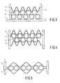
- FIG. 4 The embodiment which is shown in Figure 4 is a variant of the Figures 2 and 3.
- an embodient is shown in which two rows 4 and 5 of tubes are clamped between two elastic strips 3.
- the zig-zag period of an elastic strip 3 is equal to the zig-zag period of an engaging row of tubes.
- Figure 5 shows an embodiment in which one row 4 of tubes is clamped between two elastic strips 3 of which the zig-zag period is twice as large as the zig-zag period of the row 4 of tubes. If the zig-zag period of the elastic strips 3 is larger than twice the zig- zag period of a row of tubes it is possible that there are tubes that are not subjected to contact pressure so that these tubes are clamped in an undefined manner.
- the zig-zag period of the elastic strips 3 is therefore restricted to no more than twice the zig-zag period of a row of tubes.
- each tube from the row 4 of tubes makes good contact with an elastic strip 3 so that a defined clamping pressure remains guaranteed.
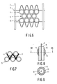
- the strips 3 engage the rows of tubes 4 and 6 and can exert pressure on the tubes in the rows 4 and 6.
- the tubes are clamped by both strips 3.
- the clamping pressure on the rows of tubes 4 and 6 is thus transferred to the row of tubes 5 and the rows 4, 5 and 6 thus receive a lasting and well-defined clamping pressure.
- FIG 7 an view is shown of an elastic strip 3 in a hold-down position.
- the elastic strip 3 is deformed by the clamping pressure so that it has the maximum contact with the tubes in the rows 4 and 5.
- Figures 1, 2, 3, 4, 5, 6 and 7 are particularly suitable for realising an assembly of coaxial conductors in clamping fit.
- Figure 8 shows a longitudinal section and Figure 9 a cross-section of a coaxial conductor according to the invention.
- the coaxial conductor comprises a core 8 of conducting material, such as copper, which is enveloped in material 9 that maintains the core at a specific distance from the braid.
- material 9 that maintains the core at a specific distance from the braid.
- Around this material 9 there is a braid 12 of woven metal wire and in between the material 9 and the braid 12 there is a rigid ring 11 of, for example, aluminium on the inside of the braid 12.
- the ring 11 makes the braid 12 assume the shape of the pipe as long as the braid 12 makes contact in clamping fit with the rigid ring 11. This contact pressure is obtained by introducing on the outside of the braid 12 a ring 13 of metal in clamping fit around the ring 11.
- the elastic strips 3 are suitably made of metal.
Landscapes
- Engineering & Computer Science (AREA)
- General Engineering & Computer Science (AREA)
- Mechanical Engineering (AREA)
- Clamps And Clips (AREA)
- Shielding Devices Or Components To Electric Or Magnetic Fields (AREA)
- Mutual Connection Of Rods And Tubes (AREA)
- Supports For Pipes And Cables (AREA)
Applications Claiming Priority (2)
| Application Number | Priority Date | Filing Date | Title |
|---|---|---|---|
| NL8801649A NL8801649A (nl) | 1988-06-29 | 1988-06-29 | Kleminrichting voor het klemmend samenhouden van buisvormige elementen. |
| NL8801649 | 1988-06-29 |
Publications (2)
| Publication Number | Publication Date |
|---|---|
| EP0352833A2 true EP0352833A2 (de) | 1990-01-31 |
| EP0352833A3 EP0352833A3 (de) | 1990-05-16 |
Family
ID=19852543
Family Applications (1)
| Application Number | Title | Priority Date | Filing Date |
|---|---|---|---|
| EP89201654A Withdrawn EP0352833A3 (de) | 1988-06-29 | 1989-06-23 | Klemmvorrichtung zur Halterung rohrförmiger Elemente in Klemmstellung |
Country Status (3)
| Country | Link |
|---|---|
| EP (1) | EP0352833A3 (de) |
| JP (1) | JPH0251605A (de) |
| NL (1) | NL8801649A (de) |
Cited By (2)
| Publication number | Priority date | Publication date | Assignee | Title |
|---|---|---|---|---|
| US20130341295A1 (en) * | 2012-06-26 | 2013-12-26 | Isovin Systems Pty Ltd | Storage rack system |
| CN109365904A (zh) * | 2018-12-12 | 2019-02-22 | 太原通泽重工有限公司 | 无缝钢管管排锯的柔性压紧装置及柔性压紧方法 |
Families Citing this family (2)
| Publication number | Priority date | Publication date | Assignee | Title |
|---|---|---|---|---|
| KR101207703B1 (ko) * | 2008-11-19 | 2012-12-03 | 신닛테츠스미킨 카부시키카이샤 | 내화 단열벽 및 건축 구조물 |
| JP2017219164A (ja) * | 2016-06-10 | 2017-12-14 | 第一ビニール株式会社 | 交差部連結用のフックバンド及びフェンス用の交差部連結用のフックバンド |
Family Cites Families (3)
| Publication number | Priority date | Publication date | Assignee | Title |
|---|---|---|---|---|
| FR856278A (fr) * | 1939-02-21 | 1940-06-10 | Alsthom Cgee | Nouveau support pour fils, barres ou câbles, notamment pour fils, barres ou câbles électriques disposés en nappe |
| DE3033790A1 (de) * | 1980-09-09 | 1982-04-22 | Deutsche Babcock Werke AG, 4200 Oberhausen | Halterung fuer rohrregister |
| EP0081013B1 (de) * | 1981-12-03 | 1986-11-05 | The Babcock & Wilcox Company | Stützstruktur für Rohre |
-
1988
- 1988-06-29 NL NL8801649A patent/NL8801649A/nl not_active Application Discontinuation
-
1989
- 1989-06-23 EP EP89201654A patent/EP0352833A3/de not_active Withdrawn
- 1989-06-26 JP JP16098189A patent/JPH0251605A/ja active Pending
Cited By (2)
| Publication number | Priority date | Publication date | Assignee | Title |
|---|---|---|---|---|
| US20130341295A1 (en) * | 2012-06-26 | 2013-12-26 | Isovin Systems Pty Ltd | Storage rack system |
| CN109365904A (zh) * | 2018-12-12 | 2019-02-22 | 太原通泽重工有限公司 | 无缝钢管管排锯的柔性压紧装置及柔性压紧方法 |
Also Published As
| Publication number | Publication date |
|---|---|
| JPH0251605A (ja) | 1990-02-21 |
| EP0352833A3 (de) | 1990-05-16 |
| NL8801649A (nl) | 1990-01-16 |
Similar Documents
| Publication | Publication Date | Title |
|---|---|---|
| US5391084A (en) | Grounding assembly for electrical distribution panels | |
| US3687500A (en) | Connecting construction for sheet members | |
| US4634199A (en) | Connector assembly for making multiple connections in a thin space | |
| US6590154B1 (en) | Accessory for fixing a wire cable tray, and wire cable tray equipped with at least such an accessory | |
| US4684183A (en) | Connector for flexible printed circuit | |
| US4635359A (en) | Method of manufacturing multi-terminal electrical connector | |
| US5832593A (en) | Splice head for insulated telecommunication wires | |
| US5124534A (en) | Heating coil support and insulation mechanism | |
| US5069254A (en) | Conduit assembly for cabling | |
| US3998268A (en) | Locking device for staggered fin-tubes | |
| US5188544A (en) | Electrical conductor terminal apparatus and method | |
| US6216320B1 (en) | Cable holding arrangement | |
| EP0352833A2 (de) | Klemmvorrichtung zur Halterung rohrförmiger Elemente in Klemmstellung | |
| US4353610A (en) | Electrical conducting strip | |
| US20200083691A1 (en) | Wire unit | |
| EP0729046A1 (de) | Ausrichtungsvorrichtung für optische Leiter | |
| SE421640B (sv) | Beklednad for tak eller veggar | |
| GB1563418A (en) | Clips supporting and spacing flanged sheets of reflective insulation | |
| US20020088644A1 (en) | Cables, cable systems, parts and methods | |
| US4255649A (en) | Flexible heating elements | |
| US4435357A (en) | Support for used fuel rods in nuclear installations | |
| EP0611636A1 (de) | Einrichtung zum Schneiden eines Produktes in Scheiben sowie Verfahren zur Herstellung einer solchen Einrichtung | |
| US7304234B2 (en) | Covering sheet and method of bending linear member with the same | |
| US2559715A (en) | Compression-connecting terminal member | |
| US3813749A (en) | A tube clamp |
Legal Events
| Date | Code | Title | Description |
|---|---|---|---|
| PUAI | Public reference made under article 153(3) epc to a published international application that has entered the european phase |
Free format text: ORIGINAL CODE: 0009012 |
|
| AK | Designated contracting states |
Kind code of ref document: A2 Designated state(s): DE FR GB NL SE |
|
| PUAL | Search report despatched |
Free format text: ORIGINAL CODE: 0009013 |
|
| AK | Designated contracting states |
Kind code of ref document: A3 Designated state(s): DE FR GB NL SE |
|
| STAA | Information on the status of an ep patent application or granted ep patent |
Free format text: STATUS: THE APPLICATION IS DEEMED TO BE WITHDRAWN |
|
| 18D | Application deemed to be withdrawn |
Effective date: 19901117 |