EP0352653B1 - Contact detector for movable objects - Google Patents
Contact detector for movable objects Download PDFInfo
- Publication number
- EP0352653B1 EP0352653B1 EP89113429A EP89113429A EP0352653B1 EP 0352653 B1 EP0352653 B1 EP 0352653B1 EP 89113429 A EP89113429 A EP 89113429A EP 89113429 A EP89113429 A EP 89113429A EP 0352653 B1 EP0352653 B1 EP 0352653B1
- Authority
- EP
- European Patent Office
- Prior art keywords
- steel balls
- members
- contact
- shaft
- contact detector
- Prior art date
- Legal status (The legal status is an assumption and is not a legal conclusion. Google has not performed a legal analysis and makes no representation as to the accuracy of the status listed.)
- Expired - Lifetime
Links
Images


Classifications
-
- B—PERFORMING OPERATIONS; TRANSPORTING
- B25—HAND TOOLS; PORTABLE POWER-DRIVEN TOOLS; MANIPULATORS
- B25J—MANIPULATORS; CHAMBERS PROVIDED WITH MANIPULATION DEVICES
- B25J19/00—Accessories fitted to manipulators, e.g. for monitoring, for viewing; Safety devices combined with or specially adapted for use in connection with manipulators
- B25J19/02—Sensing devices
- B25J19/026—Acoustical sensing devices
-
- B—PERFORMING OPERATIONS; TRANSPORTING
- B23—MACHINE TOOLS; METAL-WORKING NOT OTHERWISE PROVIDED FOR
- B23Q—DETAILS, COMPONENTS, OR ACCESSORIES FOR MACHINE TOOLS, e.g. ARRANGEMENTS FOR COPYING OR CONTROLLING; MACHINE TOOLS IN GENERAL CHARACTERISED BY THE CONSTRUCTION OF PARTICULAR DETAILS OR COMPONENTS; COMBINATIONS OR ASSOCIATIONS OF METAL-WORKING MACHINES, NOT DIRECTED TO A PARTICULAR RESULT
- B23Q16/00—Equipment for precise positioning of tool or work into particular locations not otherwise provided for
- B23Q16/02—Indexing equipment
- B23Q16/021—Indexing equipment in which only the positioning elements are of importance
-
- B—PERFORMING OPERATIONS; TRANSPORTING
- B23—MACHINE TOOLS; METAL-WORKING NOT OTHERWISE PROVIDED FOR
- B23Q—DETAILS, COMPONENTS, OR ACCESSORIES FOR MACHINE TOOLS, e.g. ARRANGEMENTS FOR COPYING OR CONTROLLING; MACHINE TOOLS IN GENERAL CHARACTERISED BY THE CONSTRUCTION OF PARTICULAR DETAILS OR COMPONENTS; COMBINATIONS OR ASSOCIATIONS OF METAL-WORKING MACHINES, NOT DIRECTED TO A PARTICULAR RESULT
- B23Q5/00—Driving or feeding mechanisms; Control arrangements therefor
- B23Q5/54—Arrangements or details not restricted to group B23Q5/02 or group B23Q5/22 respectively, e.g. control handles
- B23Q5/58—Safety devices
Definitions
- This invention relates to a method for manufacturing a contact detector for industrial robots wherein when a industrial robot comes into contact with a fixed body or fixture to undergo an external force, the contact detector detects this, thus to stop the operation of the movable object.
- FIG. 3 The appearance of a typical industrial robot using a weight body as a work is shown in FIG. 3 as the side elevational view.
- this industrial robot designated by reference numeral 20 is provided with an arm 21, a swivel portion 22 connected to the arm 21, a gripper portion 24 connected to the swivel portion 22 through a contact detector 23 for movable object, and a spot gun 26 for work affixed to the gripper portion 24.
- this industrial robot carries out a welding work by making use of chips 27 provided on the spot gun 26.
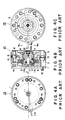
- FIG. 4 shows a contact detector as provided by a method according to the preamble of claim 1, designated by reference numeral 23, which has been already proposed by the applicant (Japanese Utility Model Application Laid Open No. 61492/1987).
- a member 1 is affixed to a wrist flange of the robot by means of bolts 15.
- a member 2 is connected to the member 1 by means of bolts 14. These members 1 and 2 are affixed to the robot side.
- a member 3 for fitting a work is connected to the member 2 side.
- the attachment of the member 3 is carried out by assembling a spherical bearing 4 into the member 3, inserting a shaft 5 into the spherical bearing 4, thereafter inserting a resilient body 6 comprised of a coned disk spring into the portion between the shaft 5 and the member 2, and screw-connecting a nut 7 over the front end portion of the shaft 5.
- Bushes 8 are assembled into the member 2 on the robot side and the member 3 on the work side, respectively. Steel balls 9 are put between these bushes 8. In this instance, these steel balls 9 are held by a retainer 10 and put between the bushes 8. Attachment thereof is carried out by tightening or fastening the nut 7.
- Reference numeral 11 denotes a switch affixed to the member 1.
- This switch 11 is inserted into the shaft 5 and is set so that it is turned ON in response to detection of a displacement of the shaft 5.
- a bolt 12 for adjustment of operating distance is opposite to the front end surface of the switch 11.
- reference numeral 11a is a nut for fixing the switch 11 serving as a double nut
- reference numeral 11b is a lead wire for the switch 11
- reference numeral 11c is a hole for penetrating the lead wire 11b therethrough
- reference numeral 12a is a coned disk spring for preventing loosening of the bolt 12 for adjustment.
- This contact detector is of a structure such that it is automatically returned to a normal state when a contact object is removed. In addition, since reproducibility is ensured, restration can be made in a short time.
- FIG. 5 shows the case that a torsional external force M2 is exerted on the member 3.
- a pressing force P by the resilient body 6 is exerted on the steel ball 9 (FIG. 5A).
- the steel ball 9 attempts to ride on the shoulder portion of the bush 8 (bush on the lift side in the figure) of the robot side member 2 to firmly come into contact therewith.
- this contact there is produced a deformation C such that the contact surface of the bush 8 becomes depressed (FIG. 5B).
- the index board consists of two reference plates (Aa, Ab) and steel balls (C) fitted in cylinderical bores (Ba, Bb) in the reference plates.
- the document JP-A-55 144 950 discloses that the upper reference plate (Ab) is pressed by predetermined load against the lower reference plate (Aa) and then the reference plate (Ab) is removed and placed over the reference plate (Aa) again so that the combination of engagement of bores (Ba) and the steel balles (C) is changed, and the same pressuring operation and pressing is carried out with respect of all possible combinations of engagement of the bores (Bb) and steel balls (C) to execute at least one complete correction for fitting to the reference plate (Aa or Ab).
- JP-A-55 144 950 The purpose of the document JP-A-55 144 950 is to provide an index board where the contact faces between the reference plate (Aa), (Ab) and the steel balls (C) have their clearances matched.
- an object of this invention is to provide a method for manufacturing a contact detector for industrial robots, which is free from deformation and/or clearance by steel balls, and which is operable with a high accuracy for a long time.
- a contact detector for movable objects comprises a plurality of steel balls put between two members and fitted into depressed portions formed by applying a pressure to the two members, a resilient body forcing one member and the steel balls to come into contact with the other member, and a switch operative when one member or the steel ball is subjected to displacement relative to the other member.
- this invention is constituted as stated above, when a pressing force is exerted, from the two members, on the steel balls put between these two members, the portions in contact with the steel balls of the two members become depressed and hardened layers are formed at the same time. Thus, the steel balls are fitted into the depressed portions of the hardened layers, and tightly held with no clearance between the steel balls and the members. In addition, even if steel balls are relatively subjected to displacement so that they firmly come into contact with the members, there is no possibility that these members are deformed.
- FIG. 1 shows an embodiment according to this invention wherein FIG. 1A is a bottom view, FIG. 1B is a side cross sectional view, and FIG. 1C is a top view.
- FIG. 2 is a cross sectional view showing means for forming hardened layers on the member 33 and the shaft 35.
- FIG. 3 is a cross sectional view of an industrial robot.
- FIG. 4 shows a prior art wherein FIG. 4A is a bottom view, FIG. 4B is a side cross sectional view, and FIG. 4C is a top view.
- FIG. 5 is a cross sectional view showing the influence by steel balls shown in FIG. 4.
- FIG. 1 The structure of an embodiment according to this invention is shown in FIG. 1.
- FIG. 1A is a bottom view when viewed from the robot side
- FIG. 1B is a side cross sectional view
- FIG. 1C is a top view when viewed from the work side.
- the structure on the robot side is composed of a member 31 affixed to a wrist flange of the robot by means of bolts 50, a member 32 affixed to the member 31 by means of bolts 47, a member 33 affixed to the work side of the member 32 by means of bolts 49, a cover 48 covering a portion of the member 32, and a cover 51 covering a portion of the end portion in the axial direction of the member 33.
- the structure on the work side is composed of an arm 34 to which a work is affixed, and a shaft 35 to which the arm 34 is affixed.
- the arm 34 is subjected to positioning by a key 42 and is affixed to the shaft 35 by tightening the bolts 43.
- the shaft 35 is provided with a cavity portion 44 formed in the axial direction thereof. By screw-connecting bolts 45 into the cavity portion 44, closing of the cavity portion 44 is carried out.
- the member 33 constituting a portion of the structure on the robot side and the shaft 35 constituting a portion of the structure on the work side constitute opposite two members.
- a plurality of steel balls 36 are fitted into the portion between these members 33 and 35.
- a tubular guide 37 displaceable in three dimensional directions is provided within the member 32 so that it is in contact with the shaft 35.
- a resilient body 38 comprised of a coil spring is inserted into the portion between the guide 37 and the member 31. In this structure, the resilient body 38 is adapted to press the shaft 35 and the steel balls 36 through the guide in the direction of the member 33.
- a dog 41 is affixed to the guide 37, and a switch 40 is affixed to the member 32 so that it is opposite to the dog 41.
- the switch 40 is set so that it is turned ON in response to detection of displacement of the dog 41, i.e. displacement of the shaft 35.
- reference numeral 39 denotes a retainer for holding steel balls 36 down between the shaft 35 and 33
- reference numeral 46 denotes a lead wire drawn from the switch 40.
- FIG. 2 shows a process for carrying out the above-mentioned work. Initially, a steel ball is set between the shaft 35 and the member 33 (FIG. 2A), and they are put therebetween. When a pressure is applied to the member 33 using a pressurizing device (FIG. 2B), the portion in contact with the steel ball of the member 33 and the shaft 35 becomes depressed by the pressure force Q. As a result, steel ball 36 is fitted into these depressed portions.
- Such a pressurization is carried out by a so-called cold forging.
- hardened layers 33a and 35a are formed at the portions in contact with the steel balls 36 of the member 33 and the shaft 35. Because these hardened layers 33a and 35a have a high hardness, even if the steel ball 36 is fixedly in contact with these hardened layers by displacement such as riding-on, there is no possibility that the shaft 35 and the member 33 are deformed. Accordingly, the detection accuracy initially set can be maintained and detection can be made with a permanent accuracy. Further, the steel balls 36 and the hardened layers 33a and 35a are securely and tightly in contact with each other, resulting in no occurrence of clearance therebetween. Thus, high accuracy positioning can be carried out.
- the contact detector for industrial robots is of a structure to pressurize steel balls put between two members to thereby fit them into the space between these two members, wherein hardened layers are formed on respective two members. Accordingly, two members undergo no displacement, and the detection accuracy can be maintained. In addition, since the two members and the steel balls are tightly in contact with each other, resulting in occurrence of no clearance. Thus, positioning accuracy is also improved.
Landscapes
- Engineering & Computer Science (AREA)
- Mechanical Engineering (AREA)
- Physics & Mathematics (AREA)
- Acoustics & Sound (AREA)
- Robotics (AREA)
- Force Measurement Appropriate To Specific Purposes (AREA)
- Measurement Of Length, Angles, Or The Like Using Electric Or Magnetic Means (AREA)
- Rolling Contact Bearings (AREA)
- Manipulator (AREA)
Description
- This invention relates to a method for manufacturing a contact detector for industrial robots wherein when a industrial robot comes into contact with a fixed body or fixture to undergo an external force, the contact detector detects this, thus to stop the operation of the movable object.
- In movable manufacturing machines, e.g., an industrial robot, etc., troubles due to contact with an external fixed body cannot be avoided by any means. It is the present stage that an approach is employed to detect such an unfavorable contact to stop the operation of the robot as soon as possible, thus to prevent the robot and the work from being damaged.
- The appearance of a typical industrial robot using a weight body as a work is shown in FIG. 3 as the side elevational view.
- As well known, this industrial robot designated by
reference numeral 20 is provided with anarm 21, aswivel portion 22 connected to thearm 21, agripper portion 24 connected to theswivel portion 22 through acontact detector 23 for movable object, and aspot gun 26 for work affixed to thegripper portion 24. Thus, this industrial robot carries out a welding work by making use ofchips 27 provided on thespot gun 26. - FIG. 4 shows a contact detector as provided by a method according to the preamble of claim 1, designated by
reference numeral 23, which has been already proposed by the applicant (Japanese Utility Model Application Laid Open No. 61492/1987). A member 1 is affixed to a wrist flange of the robot by means ofbolts 15. Amember 2 is connected to the member 1 by means ofbolts 14. Thesemembers 1 and 2 are affixed to the robot side. Amember 3 for fitting a work is connected to themember 2 side. The attachment of themember 3 is carried out by assembling a spherical bearing 4 into themember 3, inserting ashaft 5 into the spherical bearing 4, thereafter inserting aresilient body 6 comprised of a coned disk spring into the portion between theshaft 5 and themember 2, and screw-connecting a nut 7 over the front end portion of theshaft 5. Bushes 8 are assembled into themember 2 on the robot side and themember 3 on the work side, respectively.Steel balls 9 are put between thesebushes 8. In this instance, thesesteel balls 9 are held by aretainer 10 and put between thebushes 8. Attachment thereof is carried out by tightening or fastening the nut 7. Reference numeral 11 denotes a switch affixed to the member 1. This switch 11 is inserted into theshaft 5 and is set so that it is turned ON in response to detection of a displacement of theshaft 5. In this example, a bolt 12 for adjustment of operating distance is opposite to the front end surface of the switch 11. In this figure, reference numeral 11a is a nut for fixing the switch 11 serving as a double nut, reference numeral 11b is a lead wire for the switch 11, reference numeral 11c is a hole for penetrating the lead wire 11b therethrough, and reference numeral 12a is a coned disk spring for preventing loosening of the bolt 12 for adjustment. - The operation of the arrangement stated above will be described.
- When a moment M₁ in a direction indicated by an arrow is applied to the
member 3, themember 3 raises the other shoulder thereof against the coneddisk spring 6 using asteel ball 9 as a point of support. Thus, theshaft 5 is concurrently subjected to displacement. As a result, the contact of the switch 11 is opened, whereby an ON signal is output. - When a torsional external force M₂ is applied, a
steel ball 9 slips out ofbushes 8 provided in themembers 2. Similarly, theshaft 5 is subjected to displacement in a direction of opening the switch 11. Thus, an ON signal is output from the switch 11. - When tensile forces f and F are applied, an operation similar to the above is performed. Namely, the
member 3 raises the other shoulder thereof against theconed disk spring 6 using asteel ball 9 as a point of support, thus allowing theshaft 5 to be subjected to displacement in a direction of opening the switch 11. As a result, an ON signal is output. - As just described above, in accordance with this detector, when an external force is applied to the
work side member 3, a signal indicative of contact with an external fixed body is output from the switch 11. By employing a device to stop a robot using this signal, damages due to contact trouble of robot can be prevented. - This contact detector is of a structure such that it is automatically returned to a normal state when a contact object is removed. In addition, since reproducibility is ensured, restration can be made in a short time.
- However, with such a conventional detector, when an external force is exerted on
steel balls 9 betweenbushes 8, there is the possibility that the contact surface of thebush 8 may be deformed because the hardness of thebush 8 is low. FIG. 5 shows the case that a torsional external force M₂ is exerted on themember 3. A pressing force P by theresilient body 6 is exerted on the steel ball 9 (FIG. 5A). When an external force M₂ is exerted in this state, thesteel ball 9 attempts to ride on the shoulder portion of the bush 8 (bush on the lift side in the figure) of therobot side member 2 to firmly come into contact therewith. By this contact, there is produced a deformation C such that the contact surface of thebush 8 becomes depressed (FIG. 5B). Since detection accuracy initially set varies by such a deformation C, it is impossible to permanently maintain the detection accuracy. Furthermore,steel balls 9 are simply put betweenbushes 8 and held therebetween. For this reason, a clearance is apt to occur betweensteel balls 9 andbushes 8. The positioning accuracy at the working front end of the robot is lowered by this clearance. - Furthermore in the document JP-A-55 144 950 (Japanese Patent Application Laid Open NO 144 950/1980) there is described that the index board consists of two reference plates (Aa, Ab) and steel balls (C) fitted in cylinderical bores (Ba, Bb) in the reference plates.
- Further, the document JP-A-55 144 950 discloses that the upper reference plate (Ab) is pressed by predetermined load against the lower reference plate (Aa) and then the reference plate (Ab) is removed and placed over the reference plate (Aa) again so that the combination of engagement of bores (Ba) and the steel balles (C) is changed, and the same pressuring operation and pressing is carried out with respect of all possible combinations of engagement of the bores (Bb) and steel balls (C) to execute at least one complete correction for fitting to the reference plate (Aa or Ab).
- The purpose of the document JP-A-55 144 950 is to provide an index board where the contact faces between the reference plate (Aa), (Ab) and the steel balls (C) have their clearances matched.
- With the above in view, an object of this invention is to provide a method for manufacturing a contact detector for industrial robots, which is free from deformation and/or clearance by steel balls, and which is operable with a high accuracy for a long time.
- To achieve this object, a method according to claim 1 is provided.
- In this invention, an approach is employed to apply a pressure to steel balls put between two members using a press, etc. so that they are fitted therebetween. For this reason, a contact detector for movable objects according to this invention comprises a plurality of steel balls put between two members and fitted into depressed portions formed by applying a pressure to the two members, a resilient body forcing one member and the steel balls to come into contact with the other member, and a switch operative when one member or the steel ball is subjected to displacement relative to the other member.
- Since this invention is constituted as stated above, when a pressing force is exerted, from the two members, on the steel balls put between these two members, the portions in contact with the steel balls of the two members become depressed and hardened layers are formed at the same time. Thus, the steel balls are fitted into the depressed portions of the hardened layers, and tightly held with no clearance between the steel balls and the members. In addition, even if steel balls are relatively subjected to displacement so that they firmly come into contact with the members, there is no possibility that these members are deformed.
-
- FIG. 1 shows an embodiment according to this invention wherein FIG. 1A is a bottom view, FIG. 1B is a side cross sectional view, and FIG. 1C is a top view.
- FIG. 2 is a cross sectional view showing means for forming hardened layers on the
member 33 and theshaft 35. - FIG. 3 is a cross sectional view of an industrial robot.
- FIG. 4 shows a prior art wherein FIG. 4A is a bottom view, FIG. 4B is a side cross sectional view, and FIG. 4C is a top view.
- FIG. 5 is a cross sectional view showing the influence by steel balls shown in FIG. 4.
- The structure of an embodiment according to this invention is shown in FIG. 1.
- FIG. 1A is a bottom view when viewed from the robot side, FIG. 1B is a side cross sectional view, and FIG. 1C is a top view when viewed from the work side. The structure on the robot side is composed of a
member 31 affixed to a wrist flange of the robot by means ofbolts 50, amember 32 affixed to themember 31 by means ofbolts 47, amember 33 affixed to the work side of themember 32 by means ofbolts 49, acover 48 covering a portion of themember 32, and a cover 51 covering a portion of the end portion in the axial direction of themember 33. On the other hand, the structure on the work side is composed of anarm 34 to which a work is affixed, and ashaft 35 to which thearm 34 is affixed. In this embodiment, thearm 34 is subjected to positioning by a key 42 and is affixed to theshaft 35 by tightening thebolts 43. Further, theshaft 35 is provided with acavity portion 44 formed in the axial direction thereof. By screw-connectingbolts 45 into thecavity portion 44, closing of thecavity portion 44 is carried out. - In the embodiment thus constructed, the
member 33 constituting a portion of the structure on the robot side and theshaft 35 constituting a portion of the structure on the work side constitute opposite two members. A plurality ofsteel balls 36 are fitted into the portion between thesemembers tubular guide 37 displaceable in three dimensional directions is provided within themember 32 so that it is in contact with theshaft 35. In addition, aresilient body 38 comprised of a coil spring is inserted into the portion between theguide 37 and themember 31. In this structure, theresilient body 38 is adapted to press theshaft 35 and thesteel balls 36 through the guide in the direction of themember 33. When theshaft 35 is subjected to displacement against this pressing force, theguide 37 will be subjected to displacement by the same displacement quantity as that of theshaft 35 in the same direction. Adog 41 is affixed to theguide 37, and aswitch 40 is affixed to themember 32 so that it is opposite to thedog 41. Theswitch 40 is set so that it is turned ON in response to detection of displacement of thedog 41, i.e. displacement of theshaft 35. In the figure,reference numeral 39 denotes a retainer for holdingsteel balls 36 down between theshaft reference numeral 46 denotes a lead wire drawn from theswitch 40. - In the structure stated above,
steel balls 36 are put between theshaft 35 and themember 33. By applying a pressure to either of theshaft 35 and themember 33 between whichsteel balls 36 are put,steel balls 36 are fitted into the portion between theshaft 35 and themember 33. FIG. 2 shows a process for carrying out the above-mentioned work. Initially, a steel ball is set between theshaft 35 and the member 33 (FIG. 2A), and they are put therebetween. When a pressure is applied to themember 33 using a pressurizing device (FIG. 2B), the portion in contact with the steel ball of themember 33 and theshaft 35 becomes depressed by the pressure force Q. As a result,steel ball 36 is fitted into these depressed portions. Such a pressurization is carried out by a so-called cold forging. By this pressurization,hardened layers steel balls 36 of themember 33 and theshaft 35. Because thesehardened layers steel ball 36 is fixedly in contact with these hardened layers by displacement such as riding-on, there is no possibility that theshaft 35 and themember 33 are deformed. Accordingly, the detection accuracy initially set can be maintained and detection can be made with a permanent accuracy. Further, thesteel balls 36 and thehardened layers - The operation of the contact detector according to this invention will now be described.
- When a moment M₁ is applied to the
shaft 35, theshaft 35 raises the other shoulder portion of theshaft 35 against theresilient body 38 using thesteel ball 36 as a support point. As a result, theguide 37 is also subjected to displacement in synchronism with the displacement of theshaft 35. Thus, theswitch 40 becomes operative. When a torsional external forth M₂ is applied, thesteel ball 36 slips out of themember 33 or theshaft 35. As a result, theguide 37 is subjected to displacement. Thus, theswitch 40 becomes operative. When a compression force F is applied, theguide 37 is similarly subjected to displacement against the pressure force by theresilient body 38. As a result, theswitch 40 becomes operative. Accordingly, detection of an external force is securely made, so damage such as a contact trouble can be prevented. In addition, since the portions in contact with thesteel balls 36 of theshaft 35 and themember 33 are formed as hardened layers, respectively, theshaft 35 and themember 33 are not deformed. Thus, high accuracy detection can be permanently maintained. - As described above, the contact detector for industrial robots according to this invention is of a structure to pressurize steel balls put between two members to thereby fit them into the space between these two members, wherein hardened layers are formed on respective two members. Accordingly, two members undergo no displacement, and the detection accuracy can be maintained. In addition, since the two members and the steel balls are tightly in contact with each other, resulting in occurrence of no clearance. Thus, positioning accuracy is also improved.
Claims (3)
- A method for manufacturing a contact detector for
industrial robots, said method comprising the following steps:
providing
two disk-shaped members (33, 35), each of which comprises the same plurality of axially extending cylindrical holes, one (33) of the members constituting a portion of the structure of the robot, the other (35) constituting a portion of the structure on the work side,
a plurality of steel balls (36) put between corresponding holes of the two opposing members (33, 35), said balls having a diameter larger than that of the holes,
a resilient body (38) adapted to force one member (35) and said steel balls (36) to be in contact with the other member in the axial direction, and
a switch (40) operative when one member or any of said steel balls undergoes displacement relative to the other member,
characterized in that
a pressure force is applied to said members (33, 35) by means of a pressurising device, thereby depressing the portions of the members in contact with said steel balls, such that hardened layers are formed at the depressed portions (33a, 35a) and the steel balls are fitted in the depressed portions. - A method for manufacturing a contact detector for
industrial robots as set forth in claim 1, characterized by the additional step of placing a retainer (39) between said two members (33, 35) for holding respective steel balls (36). - A method for manufacturing a contact detector for
industrial robots as set forth in claim 1, characterized by the additional step of positioning a plurality of depressed portions (33a, 35a) formed between said two members (33, 35) on the same circumference and at equal pitches.
Applications Claiming Priority (2)
| Application Number | Priority Date | Filing Date | Title |
|---|---|---|---|
| JP183875/88 | 1988-07-23 | ||
| JP63183875A JPH0790495B2 (en) | 1988-07-23 | 1988-07-23 | External contact detector |
Publications (2)
| Publication Number | Publication Date |
|---|---|
| EP0352653A1 EP0352653A1 (en) | 1990-01-31 |
| EP0352653B1 true EP0352653B1 (en) | 1993-12-15 |
Family
ID=16143359
Family Applications (1)
| Application Number | Title | Priority Date | Filing Date |
|---|---|---|---|
| EP89113429A Expired - Lifetime EP0352653B1 (en) | 1988-07-23 | 1989-07-21 | Contact detector for movable objects |
Country Status (4)
| Country | Link |
|---|---|
| US (1) | US4950849A (en) |
| EP (1) | EP0352653B1 (en) |
| JP (1) | JPH0790495B2 (en) |
| DE (1) | DE68911408T2 (en) |
Families Citing this family (1)
| Publication number | Priority date | Publication date | Assignee | Title |
|---|---|---|---|---|
| DE3929311A1 (en) * | 1989-09-04 | 1991-03-07 | Hilti Ag | MILLING DEVICE FOR DEBURRING |
Family Cites Families (5)
| Publication number | Priority date | Publication date | Assignee | Title |
|---|---|---|---|---|
| US2861483A (en) * | 1953-01-12 | 1958-11-25 | Olaf C Dosen | Method and apparatus for finishing mold grooves |
| BE754653A (en) * | 1969-08-14 | 1971-02-10 | Minsky Opytny Zavod Spetsialno | DIVIDER FOR ANGULAR GRADUATION |
| JPS55144950A (en) * | 1979-04-19 | 1980-11-12 | Toyota Motor Corp | Manufacture of index board |
| JPS58105877A (en) * | 1981-12-21 | 1983-06-23 | Nissan Motor Co Ltd | Detector for steering force |
| JPH058067Y2 (en) * | 1985-10-03 | 1993-03-01 |
-
1988
- 1988-07-23 JP JP63183875A patent/JPH0790495B2/en not_active Expired - Fee Related
-
1989
- 1989-07-19 US US07/382,471 patent/US4950849A/en not_active Expired - Lifetime
- 1989-07-21 EP EP89113429A patent/EP0352653B1/en not_active Expired - Lifetime
- 1989-07-21 DE DE68911408T patent/DE68911408T2/en not_active Expired - Fee Related
Also Published As
| Publication number | Publication date |
|---|---|
| EP0352653A1 (en) | 1990-01-31 |
| US4950849A (en) | 1990-08-21 |
| JPH0790495B2 (en) | 1995-10-04 |
| DE68911408D1 (en) | 1994-01-27 |
| DE68911408T2 (en) | 1994-06-16 |
| JPH0236090A (en) | 1990-02-06 |
Similar Documents
| Publication | Publication Date | Title |
|---|---|---|
| CA2196511C (en) | Joint assembly | |
| EP3391991B1 (en) | Collet chuck | |
| EP0316190B1 (en) | Bush | |
| CA2287109C (en) | Device and method for closing a movable socket and establishing a predetermined wear indicator distance | |
| EP0683017A1 (en) | Robot hand for forging working | |
| US20090003963A1 (en) | Device and Method for Making a Screwed Connection Between a First Component and At Least One Further Component | |
| CA2365754A1 (en) | Rapid-release frangible fastener | |
| CA2376492C (en) | Device and method for simultaneously closing a movable socket while establishing a predetermined boss height and sized central orifice | |
| CA1201135A (en) | Composite leaf springs | |
| US5454150A (en) | Manufacturing methods for machining spring ends parallel at loaded length | |
| US3952390A (en) | Method of producing ball joints | |
| US5431235A (en) | Reciprocal chuck for paving breaker | |
| EP0352653A1 (en) | Contact detector for movable objects | |
| CA2127064C (en) | Two part urethane punch stripper | |
| US6073525A (en) | Method and apparatus for aligning tools provided on a C-frame | |
| EP1565670B1 (en) | Flange dressing and method for attaching a gas spring | |
| US20030213280A1 (en) | Control devices for cold-working structures | |
| JP3915195B2 (en) | Torque adjustment device for friction clutch | |
| US5625940A (en) | Robot compliance device | |
| US4019412A (en) | Torque release wrench | |
| US4207659A (en) | Forming bearing housings | |
| JPH058067Y2 (en) | ||
| JP3001317U (en) | Assembly tools for forging and forging | |
| JPH0749067Y2 (en) | Ball bearings for rotary and linear motion | |
| JPH0144283Y2 (en) |
Legal Events
| Date | Code | Title | Description |
|---|---|---|---|
| PUAI | Public reference made under article 153(3) epc to a published international application that has entered the european phase |
Free format text: ORIGINAL CODE: 0009012 |
|
| 17P | Request for examination filed |
Effective date: 19890816 |
|
| AK | Designated contracting states |
Kind code of ref document: A1 Designated state(s): DE GB SE |
|
| 17Q | First examination report despatched |
Effective date: 19910422 |
|
| RAP1 | Party data changed (applicant data changed or rights of an application transferred) |
Owner name: KABUSHIKI KAISHA YASKAWA DENKI |
|
| GRAA | (expected) grant |
Free format text: ORIGINAL CODE: 0009210 |
|
| AK | Designated contracting states |
Kind code of ref document: B1 Designated state(s): DE GB SE |
|
| REF | Corresponds to: |
Ref document number: 68911408 Country of ref document: DE Date of ref document: 19940127 |
|
| PLBE | No opposition filed within time limit |
Free format text: ORIGINAL CODE: 0009261 |
|
| STAA | Information on the status of an ep patent application or granted ep patent |
Free format text: STATUS: NO OPPOSITION FILED WITHIN TIME LIMIT |
|
| 26N | No opposition filed | ||
| EAL | Se: european patent in force in sweden |
Ref document number: 89113429.8 |
|
| REG | Reference to a national code |
Ref country code: GB Ref legal event code: IF02 |
|
| PGFP | Annual fee paid to national office [announced via postgrant information from national office to epo] |
Ref country code: DE Payment date: 20070719 Year of fee payment: 19 |
|
| PGFP | Annual fee paid to national office [announced via postgrant information from national office to epo] |
Ref country code: GB Payment date: 20070718 Year of fee payment: 19 |
|
| PGFP | Annual fee paid to national office [announced via postgrant information from national office to epo] |
Ref country code: SE Payment date: 20070704 Year of fee payment: 19 |
|
| EUG | Se: european patent has lapsed | ||
| GBPC | Gb: european patent ceased through non-payment of renewal fee |
Effective date: 20080721 |
|
| PG25 | Lapsed in a contracting state [announced via postgrant information from national office to epo] |
Ref country code: DE Free format text: LAPSE BECAUSE OF NON-PAYMENT OF DUE FEES Effective date: 20090203 |
|
| PG25 | Lapsed in a contracting state [announced via postgrant information from national office to epo] |
Ref country code: GB Free format text: LAPSE BECAUSE OF NON-PAYMENT OF DUE FEES Effective date: 20080721 |
|
| PG25 | Lapsed in a contracting state [announced via postgrant information from national office to epo] |
Ref country code: SE Free format text: LAPSE BECAUSE OF NON-PAYMENT OF DUE FEES Effective date: 20080722 |