EP0352271B1 - Method and device for the assembly of small electrical machines - Google Patents
Method and device for the assembly of small electrical machines Download PDFInfo
- Publication number
- EP0352271B1 EP0352271B1 EP88902136A EP88902136A EP0352271B1 EP 0352271 B1 EP0352271 B1 EP 0352271B1 EP 88902136 A EP88902136 A EP 88902136A EP 88902136 A EP88902136 A EP 88902136A EP 0352271 B1 EP0352271 B1 EP 0352271B1
- Authority
- EP
- European Patent Office
- Prior art keywords
- stack
- support
- bolts
- thrust members
- coplanar
- Prior art date
- Legal status (The legal status is an assumption and is not a legal conclusion. Google has not performed a legal analysis and makes no representation as to the accuracy of the status listed.)
- Expired - Lifetime
Links
- 238000000034 method Methods 0.000 title claims abstract description 33
- 238000003475 lamination Methods 0.000 claims abstract description 29
- 230000002093 peripheral effect Effects 0.000 claims abstract description 7
- 238000004804 winding Methods 0.000 claims abstract description 6
- 239000012530 fluid Substances 0.000 claims description 10
- 230000006835 compression Effects 0.000 claims description 9
- 238000007906 compression Methods 0.000 claims description 9
- 238000006243 chemical reaction Methods 0.000 claims description 5
- 239000003507 refrigerant Substances 0.000 claims description 4
- 230000002427 irreversible effect Effects 0.000 claims 2
- 238000003780 insertion Methods 0.000 claims 1
- 230000037431 insertion Effects 0.000 claims 1
- 238000004519 manufacturing process Methods 0.000 description 4
- 239000011347 resin Substances 0.000 description 4
- 229920005989 resin Polymers 0.000 description 4
- 241000722921 Tulipa gesneriana Species 0.000 description 3
- XEEYBQQBJWHFJM-UHFFFAOYSA-N Iron Chemical compound [Fe] XEEYBQQBJWHFJM-UHFFFAOYSA-N 0.000 description 2
- 238000006073 displacement reaction Methods 0.000 description 2
- 229920001187 thermosetting polymer Polymers 0.000 description 2
- 238000003466 welding Methods 0.000 description 2
- 229910000640 Fe alloy Inorganic materials 0.000 description 1
- 238000005266 casting Methods 0.000 description 1
- 238000010276 construction Methods 0.000 description 1
- 230000008602 contraction Effects 0.000 description 1
- 230000007547 defect Effects 0.000 description 1
- 230000000694 effects Effects 0.000 description 1
- 238000005470 impregnation Methods 0.000 description 1
- 229910001234 light alloy Inorganic materials 0.000 description 1
- 239000000725 suspension Substances 0.000 description 1
- 230000001360 synchronised effect Effects 0.000 description 1
Images



Classifications
-
- H—ELECTRICITY
- H02—GENERATION; CONVERSION OR DISTRIBUTION OF ELECTRIC POWER
- H02K—DYNAMO-ELECTRIC MACHINES
- H02K15/00—Processes or apparatus specially adapted for manufacturing, assembling, maintaining or repairing of dynamo-electric machines
- H02K15/02—Processes or apparatus specially adapted for manufacturing, assembling, maintaining or repairing of dynamo-electric machines of stator or rotor bodies
- H02K15/021—Magnetic cores
-
- Y—GENERAL TAGGING OF NEW TECHNOLOGICAL DEVELOPMENTS; GENERAL TAGGING OF CROSS-SECTIONAL TECHNOLOGIES SPANNING OVER SEVERAL SECTIONS OF THE IPC; TECHNICAL SUBJECTS COVERED BY FORMER USPC CROSS-REFERENCE ART COLLECTIONS [XRACs] AND DIGESTS
- Y10—TECHNICAL SUBJECTS COVERED BY FORMER USPC
- Y10T—TECHNICAL SUBJECTS COVERED BY FORMER US CLASSIFICATION
- Y10T29/00—Metal working
- Y10T29/49—Method of mechanical manufacture
- Y10T29/49002—Electrical device making
- Y10T29/49009—Dynamoelectric machine
-
- Y—GENERAL TAGGING OF NEW TECHNOLOGICAL DEVELOPMENTS; GENERAL TAGGING OF CROSS-SECTIONAL TECHNOLOGIES SPANNING OVER SEVERAL SECTIONS OF THE IPC; TECHNICAL SUBJECTS COVERED BY FORMER USPC CROSS-REFERENCE ART COLLECTIONS [XRACs] AND DIGESTS
- Y10—TECHNICAL SUBJECTS COVERED BY FORMER USPC
- Y10T—TECHNICAL SUBJECTS COVERED BY FORMER US CLASSIFICATION
- Y10T29/00—Metal working
- Y10T29/53—Means to assemble or disassemble
- Y10T29/5313—Means to assemble electrical device
- Y10T29/53143—Motor or generator
-
- Y—GENERAL TAGGING OF NEW TECHNOLOGICAL DEVELOPMENTS; GENERAL TAGGING OF CROSS-SECTIONAL TECHNOLOGIES SPANNING OVER SEVERAL SECTIONS OF THE IPC; TECHNICAL SUBJECTS COVERED BY FORMER USPC CROSS-REFERENCE ART COLLECTIONS [XRACs] AND DIGESTS
- Y10—TECHNICAL SUBJECTS COVERED BY FORMER USPC
- Y10T—TECHNICAL SUBJECTS COVERED BY FORMER US CLASSIFICATION
- Y10T29/00—Metal working
- Y10T29/53—Means to assemble or disassemble
- Y10T29/53961—Means to assemble or disassemble with work-holder for assembly
Definitions
- the present invention relates to the manufacture of rotary electrical machines and has been developed for the manufacture of hermetic motor-compressor units for refrigerant fluids.
- a method of this type is known from the document IT-A-996,643.
- a centering device is described, inter alia, which includes two concentric, "tulip"-type collets, of which the inner one is designed to contract around the shaft and the outer one is designed to expand against the surface of the bore in the stack of laminations.
- This collet ensures very accurate centering of all the laminations in the stack relative to the shaft before the stack is clamped by means of the bolts.
- the clamping torque is transmitted, by friction, from the heads of the bolts to the immediately-adjacent lamination, causing the first lamination to be forced radially against the outer collet; this force is transmitted by friction to successive laminations so that the laminations are forced along a generatrix against the outer collet and, when this is released, the accuracy of centering obtained thereby is cancelled out.
- This inaccuracy means, on the one hand, that larger air gaps have to be provided in the design stage and this reduces the efficiency of the electrical machine.
- the stator stack is impregnated with a thermosetting resin whose hardening results in a monolithic stack in which the laminations can no longer be displaced by the tightening torque.
- Impregnation is a fairly expensive operation both in capital expenditure and in time: from the latter point of view, it constitutes a lengthy additional step in the manufacture of an electrical machine.
- a stator stack of laminations is fitted around an expandable collet of the "tulip"-type. After the collet has been expanded in the bore of the stack, the latter is submitted to axial compression. While the stack is compressed the laminations are welded together on the periphery of the stack to obtain a monolithic stack.
- FR-A-2,093,227 discloses a method similar to that of FR-A-1,452,093. According to FR-A-2,093,227 use is made of a non-expandable mandrel and the laminations of the stack under axial compression, with the mandrel fitted in the bore of the stack, are welded along welding lines adjacent to the bolt holes.
- the main object of the present invention is to provide a method which enables a small electrical machine to be produced with a very small, regular air gap between the stator and the rotor without the need to impregnate or weld the core stack.
- this object is achieved by means of a method as defined in the characterising part of claim 1.
- the document US-A-4,290,291 discloses an apparatus in which a stack of laminations of an already-wound stator is submitted to axial compressive forces between pads that simulate mounting pads in a compressor.
- the compressive forces simulate and closely approximate the compressive forces that ultimately will be applied to the bolt hole regions under the heads of mounting bolts in a compressor.
- Various eccentricities and dimensional variations between the bore and bolt holes are transferred to the bore. While the stack is held with the preselected compressive force, the bore is shaped with a roller burnisher so that it will be concentric relative to the bolt holes.
- the invention also relates to a device for carrying out the method and to a small electrical machine and a unit including such a machine, produced by the method.
- unit is meant particularly, but not exclusively, a motor-compressor for refrigerant fluids in which the support for the stator is constituted by the body or crankcase of the refrigerant-fluid compressor.
- FIG. 1 to describe the motor-compressor unit, generally indicated 10, which is submitted to the method according to the invention and the principal members of the device for carrying out the method.
- the various parts of the unit and of the device also appear in the other drawings which may be referred to, and in which they are indicated by the same reference numerals.
- the motor-compressor unit 10 includes a body or crankcase 12 consisting of an iron or light alloy casting.
- the body 12 acts as a head support for the stator, generally indicated 14, of an electric motor.
- the stator 14 comprises a stack of core laminations 16 with its windings 18.
- the body 12 also supports a rotary shaft 20 which constitutes both the shaft of the electric motor and the crankshaft of the compressor, of which the casing 12 also forms a part.
- One end face of the stack 16 rests on ground, coplanar peripheral surfaces 22 of the body 12. These surfaces 22, for the reason which will be explained below, project relative to the periphery of the stack 16.
- Bolts 24 extend through the stack 16 in correspondence with the coplanar surfaces 22.
- the axes of the bolts 24 are normal to the plane defined by the surfaces 22.
- the bolts 24 are screwed into corresponding threaded holes in the body 12. Their function is to clamp the laminations of the stack 16 together and to fix the stack 16 firmly to the body 12. A further function of the bolts 24 is to fix respective annular caps 26 to the stack.
- the stacks 26 are designed to receive helical springs for suspension of the unit 10 (upside-down relative to the position shown in Figure 1) in the hermetic casing of a compressor.
- the device includes a lower assembly consisting essentially of means for supporting the body 12 in the arrangement illustrated in Figures 1 to 4,6 and 7, in which the coplanar surfaces 22 are substantially horizontal and facing upwards.
- the support means comprise three columns 28 which are movable vertically upwards and downwards, as will be better explained below. At its upper end, each column 28 carries a respective shaped support 30 on which the body 12 rests.
- each column 28 there is a respective thrust member (not shown) for driving the vertical upward and downward movement of the respective column and for exerting an upward reaction force on the body 12 through the respective column 28 and its support 30. More will be said about this force below.
- the thrust members are independent of each other both with regard to their travel in operation and to the generation of the force exerted.
- the thrust members preferably consist of linear fluid actuators, but wedges movable transversely to the direction of movement of the columns 28 and their supports 30 could be used instead.
- the device according to the invention also includes an upper assembly the principal parts of which will now be described.
- the upper assembly comprises a central column 32, movable vertically upwards and downwards, which supports beneath it a double collet 34 of the "tulip"-type, described and shown in detail in the document IT-A-996,643 to which the reader is referred.
- the double collet comprises an inner collet 36 and an outer collet 38.
- the inner collet 36 is radially contractible and arranged to grip and centre the shaft 20.
- the outer collet 38 is radially expansible and designed to engage the surface of the bore in the stack 16 and to centre the stack relative to the shaft 20. Contraction of the inner collet 36 is caused by means of a conical bush 40 and expansion of the outer collet 38 is caused by means of a conical bush 42.
- the two bushes 40 and 42 are carried by the lower ends of respective tubular, concentric shafts which are slidable within the column 32 and are driven by respective linear fluid actuators, not shown. Another actuator, not shown, causes the column 43 and the double collet 34 to descend and rise.
- the upper assembly also includes pneumatic screwdrivers 44 for screwing the respective bolts 24.
- Each screwdriver essentially comprises a rotary shaft 46, movable vertically along its axis and carrying a screwing head or socket wrench 48 at its lower end.
- the upper ends of the shafts 44 are associated with respective pneumatic motors or the like.
- the screwing heads 48 are arranged to engage the hexagonal heads of the bolts 24 within the caps 26.
- the upper assembly also includes a pressure plate 50 which is movable vertically upwards and downwards independently of the shafts 46 and has holes for the passage of these shafts.
- Sleeve-shaped thrust members 53 are associated with the plate 50.
- the sleeves 52 are slidable in the plate 50 in the direction of its movement and react against the plate itself, with the interposition of disc compression springs 53, preferably of the Bauer type.
- the sleeves 52 have respective lower radial faces 54 which, as will be better explained below, are arranged to engage the upper lamination of the stack 16 in the region immediately surrounding the caps 26.
- the sleeves have a lateral notch 55 so as not to interfere with the head of the winding 18 during the compression of the stack 16 which will be described below.
- a fluid actuator is associated with the pressure plate 50 and is arranged to cause both vertical travel of the sleeves 52, independently of the travel of the screwdrivers 44, and to exert a clamping force, of which more will be said below, on the stack 16 by means of the springs 53 and the radial faces 54 of the sleeves 52.
- the device according to the invention also includes a pair of opposite lateral slides 56 which are movable horizontally towards the unit 10 carried by the support means 28, and in the opposite direction.
- Each of the slides 56 carries a pair of fingers 58 in the form of rockers, each arranged to pivot slightly in a vertical plane.
- Each finger 58 has a downwardly-facing shoulder surface 60 against which one of the coplanar surfaces 22 of the body 12 is intended to abut for the purpose which will be explained below.
- each finger 58 can pivot between a rest position, in which it is slightly lowered as in Figures 2 and 3, and a slightly raised position, as in Figures 4,6 and 7.
- This raised position is determined by adjustment screws 62 in such a way that the shoulder surfaces 58 define a reference plane P which is strictly perpendicular to the vertical axes of the components of the upper unit of the device and, in particular, to the vertical axes of the sleeves 52.
- the device preferably consists of a work station incorporated in a assembly line in which units such as 10 are transported in a direction normal to the plane of the drawing of Figure 2.
- the slides 56 are moved closer together, in the direction of the arrows A of Figure 3, so that the shoulder surfaces 50 of the fingers 58 overlap the coplanar surfaces 22 of the frame 12.
- the three columns 28 are moved upwardly in the direction of the arrow B until the coplanar surfaces 22 abut the shoulder surfaces 60.
- the fingers 58 effect their small angular upward movement until the point at which the shoulder surfaces 60, and hence the coplanar surfaces, are brought with maximum precision into the plane P which, from this point onwards, constitutes a reference plane for the whole of the rest of the operation.
- the whole of the double collet 34 is moved downwardly in the direction of the arrow C until it is interposed between the shaft 29 and the surface of the bore in stack 16.
- the inner collet 36 is next contracted around the shaft 20 and then the outer collet 38 is expanded against the inner edges of the laminations which define the surface of the bore in the stack 16.
- all the laminations of the stack 16 are centered as exactly as possible about the shaft 20 by virtue of the fact that the laminations, being loose, can slide on each other.
- the pressure plate 50 is moved downwardly in the direction of the arrow D until the radial faces 54 of the sleeves 52 abut the upper lamination of the stack 16 around the caps 26.
- the faces 54 because of the actuator associates with the pressure plate 50, exert a clamping force normal to the reference plane P between these surfaces and the coplanar surfaces 22 of the body 12. This clamping force is equal to or at least substantially equal to that predetermined for subsequent tightening of the bolts 24.
- both the travel in operation and the clamping force exerted by each sleeve 52 are independent of those of the other sleeves 52.
- the reaction force exerted by the thrust members associated with the lower columns 28 is such as to ensure that the coplanar surfaces 22 remain firmly applied against the shoulder faces 60 of the fingers 58, that is that they remain in the reference plane P.
- FIG. 8 shows, inter alia, circular sector-shaped dotted areas 54a where the radial faces 54 exert pressure on the upper lamination of the stack 16.
- each bolt 24 there are two areas 54a in the neighbourhood of each bolt 24, located substantially symmetrically about the axis of the bolt 24 so that the resultant of the forces exerted thereby is substantially on the axis of the bolt itself.
- the method of assembling the stator 14 on its end support constituted by the body 12 of the compressor is thus completed and the various components of the device are returned to the positions of Figure 2.
- the bolted unit 10 is then moved away on the conveyor line and sent on to a station for fitting the rotor into the stator cavity.
Landscapes
- Engineering & Computer Science (AREA)
- Manufacturing & Machinery (AREA)
- Power Engineering (AREA)
- Manufacture Of Motors, Generators (AREA)
- Electrical Discharge Machining, Electrochemical Machining, And Combined Machining (AREA)
- Automobile Manufacture Line, Endless Track Vehicle, Trailer (AREA)
- Gas-Insulated Switchgears (AREA)
- Compressor (AREA)
- Applications Or Details Of Rotary Compressors (AREA)
- Iron Core Of Rotating Electric Machines (AREA)
Abstract
Description
- The present invention relates to the manufacture of rotary electrical machines and has been developed for the manufacture of hermetic motor-compressor units for refrigerant fluids.
- It relates, in the first place, to a method for assembling a stator, as defined in the preamble of claim 1.
- A method of this type is known from the document IT-A-996,643. In this document, a centering device is described, inter alia, which includes two concentric, "tulip"-type collets, of which the inner one is designed to contract around the shaft and the outer one is designed to expand against the surface of the bore in the stack of laminations.
- This collet ensures very accurate centering of all the laminations in the stack relative to the shaft before the stack is clamped by means of the bolts. When the bolts are tightened, however, the clamping torque is transmitted, by friction, from the heads of the bolts to the immediately-adjacent lamination, causing the first lamination to be forced radially against the outer collet; this force is transmitted by friction to successive laminations so that the laminations are forced along a generatrix against the outer collet and, when this is released, the accuracy of centering obtained thereby is cancelled out. This inaccuracy means, on the one hand, that larger air gaps have to be provided in the design stage and this reduces the efficiency of the electrical machine. What is worse in the case of a non-synchronous motor, is that the mutual displacement of the laminations caused by tightening of the bolts causes irregularities in the air gaps resulting in the motor being unable to reach its starting torque under load. This problem is particularly serious in the case of small hermetic motor compressors for refrigerators, particularly considering the fact that testing of the motor is carried out only on the finished compressor, that is when the compressor motor is enclosed in its hermetic casing. In this case, rejection of the compressor due to defects in its motor involves a cost corresponding to that of the finished product.
- Currently, in order to avoid displacement of the laminations during tightening of the bolts, in small electric motors, before the construction of the windings, the stator stack is impregnated with a thermosetting resin whose hardening results in a monolithic stack in which the laminations can no longer be displaced by the tightening torque. Methods of this type are known, inter alia, from the documents US-A-3,356,360 and US-A-3,573,129.
- Impregnation is a fairly expensive operation both in capital expenditure and in time: from the latter point of view, it constitutes a lengthy additional step in the manufacture of an electrical machine.
- According to another method, known from the document FR-A-1,452,093, a stator stack of laminations is fitted around an expandable collet of the "tulip"-type. After the collet has been expanded in the bore of the stack, the latter is submitted to axial compression. While the stack is compressed the laminations are welded together on the periphery of the stack to obtain a monolithic stack.
- The document FR-A-2,093,227 discloses a method similar to that of FR-A-1,452,093. According to FR-A-2,093,227 use is made of a non-expandable mandrel and the laminations of the stack under axial compression, with the mandrel fitted in the bore of the stack, are welded along welding lines adjacent to the bolt holes.
- The methods according to FR-A-1,452,093 and FR-A-2,093,227 have the drawback of requiring welding operations which constitute a lengthy additional step in the manufacture of an electrical machine.
- The main object of the present invention is to provide a method which enables a small electrical machine to be produced with a very small, regular air gap between the stator and the rotor without the need to impregnate or weld the core stack.
- According to the present invention, this object is achieved by means of a method as defined in the characterising part of claim 1.
- Thanks to this solution the following takes place:
- before tightening of the bolts, the stack, which has already been centered around the shaft with the maximum possible precision by a centering device such as the double collet of the document IT-A-996,643, is put into substantially the same final condition of compression as that in which the bolts will hold the stack after they have been tightened;
- since the bolts are tightened on to the compressed stack, the mutual friction between laminations, due to compression by the thrust members, prevents them from sliding relative to each other.
- From the documents US-A-3,356,360 and US-A-3,573,129, compression of an unwound stack, by means of a tool, with a view to impregnating it with a thermosetting resin is known but this is to achieve a different object from that of the present invention. Indeed, according to these documents, the object of the precompression is to reduce the quantity of resin necessary to impregnate the pack. After hardening of the resin, the precompression caused by the tool is released. In other words, this precompression is not used to put the stack of an already-wound stator into the condition in which it will be after tightening of the bolts.
- The document US-A-4,290,291 discloses an apparatus in which a stack of laminations of an already-wound stator is submitted to axial compressive forces between pads that simulate mounting pads in a compressor. The compressive forces simulate and closely approximate the compressive forces that ultimately will be applied to the bolt hole regions under the heads of mounting bolts in a compressor. Various eccentricities and dimensional variations between the bore and bolt holes are transferred to the bore. While the stack is held with the preselected compressive force, the bore is shaped with a roller burnisher so that it will be concentric relative to the bolt holes.
- This method does not solve the problem of the invention. After the burnishing step, which represents an additional cost, the compressive forces are released and the stator is no longer in the condition in which it will be after tightening of the bolts. Thus, also in this case the tightening of the bolts gives rise to the same drawbacks mentioned in connection with the prior art of IT-A-996,643, that is the loss of accurate centering obtained by the burnishing.
- The invention also relates to a device for carrying out the method and to a small electrical machine and a unit including such a machine, produced by the method.
- By the term unit is meant particularly, but not exclusively, a motor-compressor for refrigerant fluids in which the support for the stator is constituted by the body or crankcase of the refrigerant-fluid compressor.
- The invention will be understood more clearly from a reading of the detailed description which follows, with reference to the attached drawings which show, by way of non-limiting example, the device and the method according to the invention in their application to the assembly of a motor-compressor unit for refrigerant fluids.
- In the drawings:
- Figure 1 is a perspective view of a motor-compressor unit arranged for the stator stack of its electric motor to be centered and clamped in a device according to the invention, in which the principal parts of the device designed to cooperate with the unit to carry out the method according to the invention are also shown in the positions in which they are situated before the method is carried out,
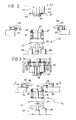
- Figure 2 is a partially-sectioned elevational view showing diagrammatically the motor-compressor unit and the parts of the device in the same positions as in Figure 1,
- Figure 3 is a view similar to that of Figure 2 showing the motor-compressor unit and the parts of the device in a position corresponding to a preparatory step of the method,
- Figure 4 is a view similar to that of Figures 2 and 3 showing the motor-compressor unit and the parts of the device in a first step of the method,
- Figure 5 is a plan view seen as indicated by the arrow V of Figure 4 showing the motor-compressor unit and certain parts of the device in the same conditions as in Figure 4, on an enlarged scale,
- Figures 6 and 7 are elevational views similar to the above which show the motor-compressor unit and the parts of the device in two subsequent steps of the method, and
- Figure 8 is a section taken in the plane indicated by the line VIII-VIII of Figure 7 on an enlarged scale, showing the unit and parts of the device in the same conditions as in Figure 7.
- Particular reference will be made to Figure 1 to describe the motor-compressor unit, generally indicated 10, which is submitted to the method according to the invention and the principal members of the device for carrying out the method. The various parts of the unit and of the device also appear in the other drawings which may be referred to, and in which they are indicated by the same reference numerals.
- The motor-
compressor unit 10 includes a body orcrankcase 12 consisting of an iron or light alloy casting. Thebody 12 acts as a head support for the stator, generally indicated 14, of an electric motor. Thestator 14 comprises a stack ofcore laminations 16 with itswindings 18. - The
body 12 also supports arotary shaft 20 which constitutes both the shaft of the electric motor and the crankshaft of the compressor, of which thecasing 12 also forms a part. - One end face of the
stack 16 rests on ground, coplanarperipheral surfaces 22 of thebody 12. Thesesurfaces 22, for the reason which will be explained below, project relative to the periphery of thestack 16. -
Bolts 24 extend through thestack 16 in correspondence with thecoplanar surfaces 22. The axes of thebolts 24 are normal to the plane defined by thesurfaces 22. - The
bolts 24 are screwed into corresponding threaded holes in thebody 12. Their function is to clamp the laminations of thestack 16 together and to fix thestack 16 firmly to thebody 12. A further function of thebolts 24 is to fix respectiveannular caps 26 to the stack. Thestacks 26 are designed to receive helical springs for suspension of the unit 10 (upside-down relative to the position shown in Figure 1) in the hermetic casing of a compressor. - The main components of the device according to the invention will now be described in its use with a motor-compressor unit such as that indicated 10.
- The device includes a lower assembly consisting essentially of means for supporting the
body 12 in the arrangement illustrated in Figures 1 to 4,6 and 7, in which thecoplanar surfaces 22 are substantially horizontal and facing upwards. In the embodiment shown, the support means comprise threecolumns 28 which are movable vertically upwards and downwards, as will be better explained below. At its upper end, eachcolumn 28 carries a respectiveshaped support 30 on which thebody 12 rests. - At the lower end of each
column 28 there is a respective thrust member (not shown) for driving the vertical upward and downward movement of the respective column and for exerting an upward reaction force on thebody 12 through therespective column 28 and itssupport 30. More will be said about this force below. For now, it will suffice to say that the thrust members are independent of each other both with regard to their travel in operation and to the generation of the force exerted. - The thrust members preferably consist of linear fluid actuators, but wedges movable transversely to the direction of movement of the
columns 28 and theirsupports 30 could be used instead. - The device according to the invention also includes an upper assembly the principal parts of which will now be described.
- The upper assembly comprises a
central column 32, movable vertically upwards and downwards, which supports beneath it adouble collet 34 of the "tulip"-type, described and shown in detail in the document IT-A-996,643 to which the reader is referred. - Some details of the
double collet 34 are shown in Figure 6 to which reference will be made briefly. - The double collet comprises an
inner collet 36 and anouter collet 38. Theinner collet 36 is radially contractible and arranged to grip and centre theshaft 20. Theouter collet 38, on the other hand, is radially expansible and designed to engage the surface of the bore in thestack 16 and to centre the stack relative to theshaft 20. Contraction of theinner collet 36 is caused by means of aconical bush 40 and expansion of theouter collet 38 is caused by means of aconical bush 42. - The two
bushes column 32 and are driven by respective linear fluid actuators, not shown. Another actuator, not shown, causes the column 43 and thedouble collet 34 to descend and rise. - The upper assembly also includes
pneumatic screwdrivers 44 for screwing therespective bolts 24. Each screwdriver essentially comprises arotary shaft 46, movable vertically along its axis and carrying a screwing head orsocket wrench 48 at its lower end. The upper ends of theshafts 44 are associated with respective pneumatic motors or the like. The screwing heads 48 are arranged to engage the hexagonal heads of thebolts 24 within thecaps 26. - The upper assembly also includes a
pressure plate 50 which is movable vertically upwards and downwards independently of theshafts 46 and has holes for the passage of these shafts. Sleeve-shapedthrust members 53 are associated with theplate 50. Thesleeves 52 are slidable in theplate 50 in the direction of its movement and react against the plate itself, with the interposition of disc compression springs 53, preferably of the Bauer type. - The
sleeves 52 have respective lower radial faces 54 which, as will be better explained below, are arranged to engage the upper lamination of thestack 16 in the region immediately surrounding thecaps 26. In the embodiment shown, the sleeves have alateral notch 55 so as not to interfere with the head of the winding 18 during the compression of thestack 16 which will be described below. - A fluid actuator is associated with the
pressure plate 50 and is arranged to cause both vertical travel of thesleeves 52, independently of the travel of thescrewdrivers 44, and to exert a clamping force, of which more will be said below, on thestack 16 by means of thesprings 53 and the radial faces 54 of thesleeves 52. - The device according to the invention also includes a pair of opposite lateral slides 56 which are movable horizontally towards the
unit 10 carried by the support means 28, and in the opposite direction. Each of theslides 56 carries a pair offingers 58 in the form of rockers, each arranged to pivot slightly in a vertical plane. Eachfinger 58 has a downwardly-facingshoulder surface 60 against which one of thecoplanar surfaces 22 of thebody 12 is intended to abut for the purpose which will be explained below. For now, it will suffice to say that eachfinger 58 can pivot between a rest position, in which it is slightly lowered as in Figures 2 and 3, and a slightly raised position, as in Figures 4,6 and 7. This raised position is determined byadjustment screws 62 in such a way that the shoulder surfaces 58 define a reference plane P which is strictly perpendicular to the vertical axes of the components of the upper unit of the device and, in particular, to the vertical axes of thesleeves 52. - Reference will now be made to Figure 2 and to subsequent Figures to describe the operation of the device and the method carried out thereby.
- The device preferably consists of a work station incorporated in a assembly line in which units such as 10 are transported in a direction normal to the plane of the drawing of Figure 2.
- When a
unit 10 arrives at the station, it is placed, in a manner not shown, on the supports which, together with theircolumns 28, are in a lowered position. - In this preliminary step of Figure 2, the whole of the upper assembly is raised and the
slides 56 are moved apart and away from theunit 10. - It should be mentioned that, in the
unit 10 which arrives at the station, thebolts 24 are screwed into thebody 12 but not tightened so that the laminations of thestack 16 are loose. - In a subsequent step of the method, the
slides 56 are moved closer together, in the direction of the arrows A of Figure 3, so that the shoulder surfaces 50 of thefingers 58 overlap thecoplanar surfaces 22 of theframe 12. - In a further subsequent step illustrated in Figure 4, the three
columns 28 are moved upwardly in the direction of the arrow B until thecoplanar surfaces 22 abut the shoulder surfaces 60. In this way, thefingers 58 effect their small angular upward movement until the point at which the shoulder surfaces 60, and hence the coplanar surfaces, are brought with maximum precision into the plane P which, from this point onwards, constitutes a reference plane for the whole of the rest of the operation. - The situation of Figure 4 is clarified by the plan view of Figure 5.
- In the next step of the method illustrated in Figure 6, the whole of the
double collet 34 is moved downwardly in the direction of the arrow C until it is interposed between the shaft 29 and the surface of the bore instack 16. Theinner collet 36 is next contracted around theshaft 20 and then theouter collet 38 is expanded against the inner edges of the laminations which define the surface of the bore in thestack 16. In this operation, all the laminations of thestack 16 are centered as exactly as possible about theshaft 20 by virtue of the fact that the laminations, being loose, can slide on each other. - In the next step, illustrated in Figure 7, the
pressure plate 50 is moved downwardly in the direction of the arrow D until the radial faces 54 of thesleeves 52 abut the upper lamination of thestack 16 around thecaps 26. - The faces 54, because of the actuator associates with the
pressure plate 50, exert a clamping force normal to the reference plane P between these surfaces and thecoplanar surfaces 22 of thebody 12. This clamping force is equal to or at least substantially equal to that predetermined for subsequent tightening of thebolts 24. By virtue of thesprings 53, both the travel in operation and the clamping force exerted by eachsleeve 52 are independent of those of theother sleeves 52. - The reaction force exerted by the thrust members associated with the
lower columns 28 is such as to ensure that thecoplanar surfaces 22 remain firmly applied against the shoulder faces 60 of thefingers 58, that is that they remain in the reference plane P. - The plan view of Figure 8 shows, inter alia, circular sector-shaped
dotted areas 54a where the radial faces 54 exert pressure on the upper lamination of thestack 16. - As will be seen, there are two
areas 54a in the neighbourhood of eachbolt 24, located substantially symmetrically about the axis of thebolt 24 so that the resultant of the forces exerted thereby is substantially on the axis of the bolt itself. - Whilst the
stack 16 is clamped by the thrust members constituted by thesleeves 52, thescrewdrivers 44 are lowered (arrow E) and their screwingheads 48 engage the heads of thebolts 24. - Finally, the
shafts 46 of thescrewdrivers 44 are rotated (arrow F), fully tightening thebolts 12 with a torque such as to exert the predetermined clamping force on the pack by means of the bolts themselves. - The method of assembling the
stator 14 on its end support constituted by thebody 12 of the compressor is thus completed and the various components of the device are returned to the positions of Figure 2. The boltedunit 10 is then moved away on the conveyor line and sent on to a station for fitting the rotor into the stator cavity.
Claims (15)
- A method for assembling a stator (14) formed by a stack of core laminations (16) and its windings (18) on to a respective head support (12) of a small rotary electrical machine in a position concentric with a rotary shaft (20) mounted in the support (12), in which the periphery of one end face of the stack (16) of laminations rests on peripheral coplanar surfaces (22) of the support (12) which define a reference plane (P), a centering device (34) is interposed between the shaft (20) and the stack (16), and the stack and the support are held together by means of peripheral bolts (24) inserted in regions corresponding with the coplanar surfaces (22) of the support (12), perpendicular to these surfaces, and are screwed into the support, characterised in that before the bolts (24) are tightened, the stack (16) is clamped between the coplanar surfaces (22) on one side and thrust members (52) on the other side, said thrust members (52) being applied to the other end face of the stack (16) in regions also corresponding with the regions of insertion of the bolts (24), with clamping forces normal to the reference plane (P) and at least substantially equal to those predetermined for the tightening of the bolts (24), the bolts (24) are then tightened with the predetermined tightening force and the clamping force applied by the thrust members (52) is then released.
- A method according to claim 1, characterised in that before the stack (16) is clamped by means of the thrust members (52), the regions of the coplanar surfaces (22) of the support (12) which project from the periphery of the stack (16) are applied against shoulder surfaces (60), which are also coplanar, by irreversible forces reacting in the direction opposite to the force which will be exerted by the thrust member (52), and in that forces are exerted by the thrust members (52) normal to the plane defined by the shoulder surfaces (60).
- A method according to claim 2, characterised in that the reaction forces are exerted by means of thrust members which are independent of each other with respect both to their travel in operation and to the generation of the force exerted.
- A method according to claim 1 or claim 2, characterised in that thrust members (52) are used which are independent of each other with respect both to their travel in operation and to the generation of the clamping force exerted.
- A method according to claim 1 or claim 4, characterised in that pressures exerted by the thrust members (52) are distributed in correspondence with each bolt (24) in two areas (54a) which are symmetrical about the axis of the bolt (24).
- A device for assembling a stator, formed by a stack of core laminations (16) and its windings (18) on to a respective head support (12) of a small rotary electrical machine, in a position concentric with a rotary shaft (20) mounted in the support (12), in which the periphery of one end face of the stack (16) rests on the peripheral coplanar surfaces (22) of the support (12) which define a reference plane (P) , and the stack (16) is traversed by peripheral bolts (24) situated in correspondence with the coplanar surfaces (22) , perpendicular to these surfaces and which are screwed into the support, the device including means for supporting the support, a centering device (34) which can be interposed between the shaft (20) and the stack (16) and means (44) for tightening the bolts, characterised in that it also includes thrust members (52) for clamping the stack (16) between the thrust members and the coplanar surfaces (22) , before the bolts (24) are tightened and while the centering device (34) keeps the stack centered relative to the shaft (20), with clamping forces normal to the reference plane (P) and at least substantially equal to those predetermined for the tightening of the bolts (24).
- A device according to claim 6, characterised in that it also includes coplanar shoulder surfaces (60) against which regions of the coplanar surfaces (22) projecting relative to the periphery of the stack (16) can be applied before the stack is clamped by the thrust members (52), and the support means (30) for the support (12) are movable towards the shoulder surfaces (60) to apply the projecting regions of the coplanar surfaces (20) against the shoulder surfaces (60) with irreversible forces reacting in the direction opposite to the force which will be exerted by the thrust members (52), and in that the thrust members (52) are arranged so as to exert forces on the stack (16) normal to a plane defined by the shoulder surfaces (60).
- A device according to claim 7, characterised in that the shoulder surfaces (60) are each formed by a respective pivoting finger (58) with which is associated a respective adjustable stop (62) for defining a stop position for the pivoting fingers (58) in which the shoulder surfaces (60) engaged by the respective projecting regions of the coplanar surfaces (22) are situated in the reference plane (P).
- A device according to claim 7, characterised in that the support means consist of several supports (30) movable independently of each other, each of which is associated with a respective thrust member arranged to generate a reaction force independent of that of the other thrust members.
- A device according to claim 9, characterised in that the thrust members are linear fluid actuators.
- A device according to claim 9, characterised in that the thrust members consist of wedges movable transversely to the direction of movement of the supports (30) and cooperating with the supports to cause the movement of the latter and generate their reaction forces.
- A device according to claim 6, characterised in that the means for tightening the bolts are constituted, in known manner, by screwdrivers (44) which comprise an axially movable rotary shaft (46) with a terminal screwing head (48), in that the thrust members consist of sleeves (52) each of which surrounds a screwing head (48), has a flat radial end face (54) for engagement with the stack (16) in the neighbourhood of the axis of a respective bolt (24), and is carried slidably along the axis of the respective screwdriver (44) by the pressure plate (50) and reacts against this plate (50) with the interposition of a compression spring (53) , and in that the pressure plate (50) is movable along the shafts (46) of the screwdrivers (44) and independently of these and is associated with a fluid actuator for moving the pressure plate (50) and its sleeves (52) towards the stack (16) and for exerting the clamping force by means of the radial faces (54) of the sleeves (52) through the compression springs (53).
- A device according to claim 12, characterised in that each radial face (54) is such as to engage the stack (16) in two areas (54a) which are substantially symmetrical about the axis of the respective bolt (24).
- A small electrical machine or unit including such a machine, in which a stator stack of core laminations (16) is mounted on a head support (12) in which the rotary shaft (20) of the motor is rotatably mounted, characterised in that the stack (16) and the shaft (20) are centered with respect to each other by the method according to any of the claims 1 to 5.
- A motor compressor unit for refrigerant fluids comprising an electric motor and a compressor, in which a stator stack of core laminations (16) of the motor is mounted on the body (12) of the compressor, which acts as a head support for the stator of the motor and in which is rotatably mounted the rotary shaft (20) common to the motor and to the compressor, characterised in that the stack (16) and the shaft (20) are centered with respect to each other by the method according to any one of claims 1 to 5.
Priority Applications (1)
| Application Number | Priority Date | Filing Date | Title |
|---|---|---|---|
| AT88902136T ATE84383T1 (en) | 1987-04-01 | 1988-03-04 | METHOD AND DEVICE FOR ASSEMBLING SMALL ELECTRICAL MACHINES. |
Applications Claiming Priority (2)
| Application Number | Priority Date | Filing Date | Title |
|---|---|---|---|
| IT6725787 | 1987-04-01 | ||
| IT8767257A IT1208363B (en) | 1987-04-01 | 1987-04-01 | PROCEDURE AND DEVICE FOR THE ASSEMBLY OF SMALL ELECTRIC ROTARY MACHINES AND GROUPS THAT INCLUDE THEM IN PARTICULAR MOTOR-COMPRESSOR GROUPS FOR REFRIGERANT FLUIDS AND MACHINES AND GROUPS ASSEMBLED WITH THE PROCEDURE |
Publications (2)
| Publication Number | Publication Date |
|---|---|
| EP0352271A1 EP0352271A1 (en) | 1990-01-31 |
| EP0352271B1 true EP0352271B1 (en) | 1993-01-07 |
Family
ID=11300908
Family Applications (1)
| Application Number | Title | Priority Date | Filing Date |
|---|---|---|---|
| EP88902136A Expired - Lifetime EP0352271B1 (en) | 1987-04-01 | 1988-03-04 | Method and device for the assembly of small electrical machines |
Country Status (10)
| Country | Link |
|---|---|
| US (2) | US5010638A (en) |
| EP (1) | EP0352271B1 (en) |
| JP (1) | JPH02502871A (en) |
| AT (1) | ATE84383T1 (en) |
| BR (1) | BR8807444A (en) |
| DE (1) | DE3877356T2 (en) |
| DK (1) | DK481489A (en) |
| ES (1) | ES2010252A6 (en) |
| IT (1) | IT1208363B (en) |
| WO (1) | WO1988007781A1 (en) |
Families Citing this family (24)
| Publication number | Priority date | Publication date | Assignee | Title |
|---|---|---|---|---|
| US5485670A (en) * | 1993-08-30 | 1996-01-23 | Alliance Winding Equipment, Inc. | Stator coil lacing machine |
| US5511502A (en) * | 1994-02-25 | 1996-04-30 | Alliance Winding Equipment, Inc. | Automatic loader for a stator coil lacing machine |
| US5404306A (en) * | 1994-04-20 | 1995-04-04 | Rockwell International Corporation | Vehicular traffic monitoring system |
| GB2310545B (en) | 1996-02-22 | 2000-04-19 | Honda Motor Co Ltd | Stator core and method and apparatus for assembling same |
| US6122817A (en) * | 1997-09-19 | 2000-09-26 | Alliedsignal Inc. | Rotor assembly having lamination stack that is separately piloted and clamped |
| US20020079783A1 (en) * | 2000-12-22 | 2002-06-27 | Hopeck James Frederick | Air gap winding method and support structure for a superconducting generator and method for forming the same |
| US6523247B2 (en) * | 2001-01-03 | 2003-02-25 | Copeland Corporation | Motor stator with loose laminations |
| DE10137270A1 (en) * | 2001-07-31 | 2003-02-20 | Aloys Wobben | Wind energy installation has a ring generator with a stator having grooves spaced at intervals on an internal or external periphery for receiving a stator winding. |
| JP3904937B2 (en) * | 2002-02-08 | 2007-04-11 | 株式会社ミツバ | Motor assembly equipment |
| DE10341443A1 (en) * | 2003-09-09 | 2005-05-12 | Buhler Motor Gmbh | Adjusting drive with support of injection mouldable plastics material, on which is secured at least one stator part in form of stacked sheet meal laminations by at least one steel pin passing through stator part(s) and support |
| US7415758B2 (en) * | 2003-09-10 | 2008-08-26 | Minebea Co., Ltd. | Device to press the shaft of a rotor into a stator housing |
| JP4401146B2 (en) * | 2003-11-10 | 2010-01-20 | 株式会社マキタ | Motor manufacturing method and manufacturing apparatus |
| US7565731B2 (en) * | 2005-08-01 | 2009-07-28 | Honeywell International Inc. | Methods of manufacturing a rotor assembly |
| SI1859876T1 (en) * | 2006-05-24 | 2009-08-31 | Ernesto Malvestiti S P A | Centering device for blanking dies |
| JP4523609B2 (en) * | 2007-01-26 | 2010-08-11 | 三菱電機株式会社 | Manufacturing method of stator of rotating electric machine |
| TWM343834U (en) * | 2008-05-15 | 2008-11-01 | Mustek Systems Inc | Device for locking lens |
| US7886426B2 (en) * | 2008-07-22 | 2011-02-15 | Honda Motor Co., Ltd. | Stator manufacturing apparatus |
| EP2421128A4 (en) * | 2009-04-15 | 2016-12-21 | Toyota Motor Co Ltd | STATOR AND PRODUCTION METHOD THEREFOR |
| CN104625992B (en) * | 2013-11-06 | 2017-12-05 | 富泰华工业(深圳)有限公司 | Positioner |
| US12068659B2 (en) | 2019-12-05 | 2024-08-20 | Sharkninja Operating Llc | Diffuser for an electric motor |
| CN112653304B (en) * | 2020-12-22 | 2021-12-07 | 温岭市南海电器有限公司 | Centering device for motor stator and rotor punching sheet production |
| JP7222011B2 (en) * | 2021-03-18 | 2023-02-14 | 本田技研工業株式会社 | Coil mounting device and coil mounting method |
| MX2023013024A (en) * | 2021-05-06 | 2023-11-16 | Marsilli S P A | Method for the making of a stator for electric motors, and respective stator for electric motors. |
| JP7647658B2 (en) * | 2022-04-12 | 2025-03-18 | 株式会社デンソー | Manufacturing apparatus for rotating electric machine and manufacturing method for rotating electric machine |
Family Cites Families (5)
| Publication number | Priority date | Publication date | Assignee | Title |
|---|---|---|---|---|
| US3490143A (en) * | 1964-06-26 | 1970-01-20 | Bobbie B Hull | Method of manufacturing a core for an electrical inductive device |
| FR1452093A (en) * | 1965-06-25 | 1966-02-25 | Thomson Houston Comp Francaise | Improvements to dynamoelectric machine stators and their manufacturing processes |
| FR2093227A5 (en) * | 1970-06-05 | 1972-01-28 | Wagner Electric Corp | |
| US3864822A (en) * | 1974-04-29 | 1975-02-11 | Farlow Associates Inc | Apparatus and a method for final assembling of dynamoelectric machines |
| US4290291A (en) * | 1977-09-21 | 1981-09-22 | General Electric Company | Apparatus for making dynamoelectric machine stators |
-
1987
- 1987-04-01 IT IT8767257A patent/IT1208363B/en active
-
1988
- 1988-03-04 WO PCT/EP1988/000165 patent/WO1988007781A1/en not_active Ceased
- 1988-03-04 BR BR888807444A patent/BR8807444A/en not_active IP Right Cessation
- 1988-03-04 AT AT88902136T patent/ATE84383T1/en not_active IP Right Cessation
- 1988-03-04 JP JP63502206A patent/JPH02502871A/en active Pending
- 1988-03-04 EP EP88902136A patent/EP0352271B1/en not_active Expired - Lifetime
- 1988-03-04 US US07/411,533 patent/US5010638A/en not_active Expired - Lifetime
- 1988-03-04 DE DE8888902136T patent/DE3877356T2/en not_active Expired - Lifetime
- 1988-03-30 ES ES8800979A patent/ES2010252A6/en not_active Expired
-
1989
- 1989-09-29 DK DK481489A patent/DK481489A/en not_active Application Discontinuation
-
1990
- 1990-11-26 US US07/617,753 patent/US5062200A/en not_active Expired - Lifetime
Also Published As
| Publication number | Publication date |
|---|---|
| DE3877356T2 (en) | 1993-05-27 |
| BR8807444A (en) | 1990-05-22 |
| EP0352271A1 (en) | 1990-01-31 |
| DK481489A (en) | 1989-11-28 |
| US5062200A (en) | 1991-11-05 |
| ES2010252A6 (en) | 1989-11-01 |
| IT1208363B (en) | 1989-06-12 |
| IT8767257A0 (en) | 1987-04-01 |
| DK481489D0 (en) | 1989-09-29 |
| US5010638A (en) | 1991-04-30 |
| WO1988007781A1 (en) | 1988-10-06 |
| DE3877356D1 (en) | 1993-02-18 |
| ATE84383T1 (en) | 1993-01-15 |
| JPH02502871A (en) | 1990-09-06 |
Similar Documents
| Publication | Publication Date | Title |
|---|---|---|
| US5062200A (en) | Device for the assembly of small electrical machines | |
| CA1056894A (en) | Dynamoelectric machine prestressed rotor shaft and method of manufacturing the same | |
| CA1097584A (en) | Pallet registry system | |
| US3320660A (en) | Methods for assembling end shield members in dynamoelectric machines | |
| US6898835B1 (en) | Method for assembling a blower wheel | |
| CA1048243A (en) | Method and apparatus for forming winding end turns | |
| US3050832A (en) | Method of manufacturing a motor compressor unit | |
| US5725339A (en) | Crankshaft working method | |
| US4003116A (en) | Apparatus for setting insulators and pressing end turns | |
| US3786561A (en) | Method for use in manufacturing dynamoelectric machine | |
| US5454150A (en) | Manufacturing methods for machining spring ends parallel at loaded length | |
| US6523247B2 (en) | Motor stator with loose laminations | |
| US3909642A (en) | Dynamoelectric machine | |
| US5282309A (en) | Apparatus for constructing an unbalanced rotor | |
| US4051595A (en) | Methods for setting insulators and pressing end turns | |
| US3464107A (en) | Compressor-motor assembly | |
| CN113198962A (en) | Machine tool spindle forging device | |
| US3493794A (en) | Method of manufacture of electric motor and electric motor stator construction | |
| CN116372542B (en) | Fully automatic rotor bearing press machine | |
| EP0045308A1 (en) | Method and apparatus for air gap setting | |
| US3953275A (en) | Method and apparatus for liquid adhesive application | |
| CN120880082B (en) | Rounding mechanism with center positioning function | |
| JP3296903B2 (en) | Hollow cylinder assembling device with divided parts | |
| CA1053881A (en) | Method and apparatus for pressing end turns | |
| CN215146912U (en) | Fixture tool suitable for finish machining of various gas turbine blades |
Legal Events
| Date | Code | Title | Description |
|---|---|---|---|
| PUAI | Public reference made under article 153(3) epc to a published international application that has entered the european phase |
Free format text: ORIGINAL CODE: 0009012 |
|
| 17P | Request for examination filed |
Effective date: 19890923 |
|
| AK | Designated contracting states |
Kind code of ref document: A1 Designated state(s): AT BE CH DE FR GB IT LI LU NL SE |
|
| 17Q | First examination report despatched |
Effective date: 19911121 |
|
| RAP1 | Party data changed (applicant data changed or rights of an application transferred) |
Owner name: WHIRLPOOL ITALIA S.R.L. |
|
| GRAA | (expected) grant |
Free format text: ORIGINAL CODE: 0009210 |
|
| AK | Designated contracting states |
Kind code of ref document: B1 Designated state(s): AT BE CH DE FR GB IT LI LU NL SE |
|
| PG25 | Lapsed in a contracting state [announced via postgrant information from national office to epo] |
Ref country code: CH Effective date: 19930107 Ref country code: BE Effective date: 19930107 Ref country code: NL Effective date: 19930107 Ref country code: LI Effective date: 19930107 Ref country code: AT Effective date: 19930107 Ref country code: SE Effective date: 19930107 |
|
| REF | Corresponds to: |
Ref document number: 84383 Country of ref document: AT Date of ref document: 19930115 Kind code of ref document: T |
|
| ITF | It: translation for a ep patent filed | ||
| REF | Corresponds to: |
Ref document number: 3877356 Country of ref document: DE Date of ref document: 19930218 |
|
| PG25 | Lapsed in a contracting state [announced via postgrant information from national office to epo] |
Ref country code: LU Free format text: LAPSE BECAUSE OF NON-PAYMENT OF DUE FEES Effective date: 19930331 |
|
| ET | Fr: translation filed | ||
| PG25 | Lapsed in a contracting state [announced via postgrant information from national office to epo] |
Ref country code: GB Effective date: 19930407 |
|
| REG | Reference to a national code |
Ref country code: CH Ref legal event code: PL |
|
| NLV1 | Nl: lapsed or annulled due to failure to fulfill the requirements of art. 29p and 29m of the patents act | ||
| PLBE | No opposition filed within time limit |
Free format text: ORIGINAL CODE: 0009261 |
|
| STAA | Information on the status of an ep patent application or granted ep patent |
Free format text: STATUS: NO OPPOSITION FILED WITHIN TIME LIMIT |
|
| GBPC | Gb: european patent ceased through non-payment of renewal fee |
Effective date: 19930407 |
|
| 26N | No opposition filed | ||
| PG25 | Lapsed in a contracting state [announced via postgrant information from national office to epo] |
Ref country code: IT Free format text: LAPSE BECAUSE OF NON-PAYMENT OF DUE FEES;WARNING: LAPSES OF ITALIAN PATENTS WITH EFFECTIVE DATE BEFORE 2007 MAY HAVE OCCURRED AT ANY TIME BEFORE 2007. THE CORRECT EFFECTIVE DATE MAY BE DIFFERENT FROM THE ONE RECORDED. Effective date: 20050304 |
|
| PGFP | Annual fee paid to national office [announced via postgrant information from national office to epo] |
Ref country code: DE Payment date: 20070226 Year of fee payment: 20 |
|
| REG | Reference to a national code |
Ref country code: FR Ref legal event code: ST Effective date: 20071130 |
|
| PGFP | Annual fee paid to national office [announced via postgrant information from national office to epo] |
Ref country code: FR Payment date: 20070331 Year of fee payment: 20 |