EP0352032B1 - An image forming apparatus - Google Patents
An image forming apparatus Download PDFInfo
- Publication number
- EP0352032B1 EP0352032B1 EP89307158A EP89307158A EP0352032B1 EP 0352032 B1 EP0352032 B1 EP 0352032B1 EP 89307158 A EP89307158 A EP 89307158A EP 89307158 A EP89307158 A EP 89307158A EP 0352032 B1 EP0352032 B1 EP 0352032B1
- Authority
- EP
- European Patent Office
- Prior art keywords
- sensitivity information
- light
- sensitivity
- image forming
- sheet
- Prior art date
- Legal status (The legal status is an assumption and is not a legal conclusion. Google has not performed a legal analysis and makes no representation as to the accuracy of the status listed.)
- Expired - Lifetime
Links
Images


Classifications
-
- G—PHYSICS
- G03—PHOTOGRAPHY; CINEMATOGRAPHY; ANALOGOUS TECHNIQUES USING WAVES OTHER THAN OPTICAL WAVES; ELECTROGRAPHY; HOLOGRAPHY
- G03C—PHOTOSENSITIVE MATERIALS FOR PHOTOGRAPHIC PURPOSES; PHOTOGRAPHIC PROCESSES, e.g. CINE, X-RAY, COLOUR, STEREO-PHOTOGRAPHIC PROCESSES; AUXILIARY PROCESSES IN PHOTOGRAPHY
- G03C1/00—Photosensitive materials
- G03C1/76—Photosensitive materials characterised by the base or auxiliary layers
- G03C1/765—Photosensitive materials characterised by the base or auxiliary layers characterised by the shape of the base, e.g. arrangement of perforations, jags
-
- G—PHYSICS
- G03—PHOTOGRAPHY; CINEMATOGRAPHY; ANALOGOUS TECHNIQUES USING WAVES OTHER THAN OPTICAL WAVES; ELECTROGRAPHY; HOLOGRAPHY
- G03F—PHOTOMECHANICAL PRODUCTION OF TEXTURED OR PATTERNED SURFACES, e.g. FOR PRINTING, FOR PROCESSING OF SEMICONDUCTOR DEVICES; MATERIALS THEREFOR; ORIGINALS THEREFOR; APPARATUS SPECIALLY ADAPTED THEREFOR
- G03F7/00—Photomechanical, e.g. photolithographic, production of textured or patterned surfaces, e.g. printing surfaces; Materials therefor, e.g. comprising photoresists; Apparatus specially adapted therefor
- G03F7/002—Photomechanical, e.g. photolithographic, production of textured or patterned surfaces, e.g. printing surfaces; Materials therefor, e.g. comprising photoresists; Apparatus specially adapted therefor using materials containing microcapsules; Preparing or processing such materials, e.g. by pressure; Devices or apparatus specially designed therefor
- G03F7/0022—Devices or apparatus
-
- G—PHYSICS
- G03—PHOTOGRAPHY; CINEMATOGRAPHY; ANALOGOUS TECHNIQUES USING WAVES OTHER THAN OPTICAL WAVES; ELECTROGRAPHY; HOLOGRAPHY
- G03B—APPARATUS OR ARRANGEMENTS FOR TAKING PHOTOGRAPHS OR FOR PROJECTING OR VIEWING THEM; APPARATUS OR ARRANGEMENTS EMPLOYING ANALOGOUS TECHNIQUES USING WAVES OTHER THAN OPTICAL WAVES; ACCESSORIES THEREFOR
- G03B2227/00—Photographic printing apparatus
- G03B2227/32—Projection printing apparatus, e.g. enlarging apparatus, copying camera
- G03B2227/325—Microcapsule copiers
Definitions
- the present invention relates to an image forming apparatus having a media cartridge for forming an image, wherein color corrections are made for forming a full color image according to the sensitivity of a light receiving sheet accommodated in the media cartridge.
- Japanese Laid-Open Patent Publication No. 58-88739 discloses an image forming method using a light receiving sheet coated with microcapsules enclosing photopolymerizable materials and image forming materials and an image receiving sheet coated with developer that reacts with the image forming materials to produce colors.
- the light receiving sheet is accommodated in a cartridge.
- the cartridge is in the form of a roll and with a loading leader sheet connected to the leading edge thereon, the cartridge being set in the image forming apparatus in a detachable way.
- the leader sheet is made of a shading material.
- the invention described herein makes possible the objectives of (1) providing an image forming apparatus that automatically makes color corrections, when a fresh media cartridge is set, by detecting the sensitivity of the light receiving sheet accommodated in the cartridge before entering the copy ready state; and (2) providing an image forming apparatus that detects the sensitivity information of microcapsules, which varies from lot to lot of light receiving sheet production, after the media cartridge is loaded and before automatic loading is completed and the ready state is entered, and makes color corrections on the basis of the thus detected information, and therefore, because the operator does not have to make test copies for adjustment of copy quality, it is possible to cut down on time and cost, while obtaining copy image of good quality.
- Figure 1 is a plan view of a leader sheet connected to the leading edge of a light receiving sheet accommodated in a media cartridge to be loaded into an image forming apparatus of the invention.
- Figure 2 is a perspective view showing the loading of the leader sheet into the apparatus.
- Figures 3A and 3B are diagrams showing recordings on a light receiving sheet sensitivity information recording means provided on the edge of the leader sheet.
- Figure 4 is a plan view of the light receiving sensor of the sensitivity information sensor provided in the image forming apparatus.
- Figure 5 is a cross sectional view of the lens section of the image forming apparatus.
- Figure 6 are plan views of the color correction filters built into the lens section.
- Figure 7 is a perspective view of the color correction filter and the stepping motor connected thereto.
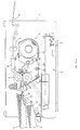
- Figure 10 is a front view of the image forming apparatus.
- the present invention provides an image forming apparatus in which, when a fresh media cartridge is loaded with a leader sheet, a sensitivity information sensor in the apparatus reads sensitivity information that has been pre-recorded on the sensitivity information recording means of the leader sheet, and color corrections are made by recognizing the difference from the standard sensitivity and control of the color filters, etc.
- Figure 10 shows an image forming apparatus of the present invention.
- an original table 2 On the top surface of an apparatus 1 is mounted an original table 2, beneath which is disposed an optical system 3 comprising a light source, four reflecting mirrors and a lens.
- the optical system 3 moves in the direction indicated by the arrow in Figure 10 to scan the original.
- In the right side panel of the apparatus 1 are loaded two paper cassettes 4 .
- the paper cassettes 4 hold cutform paper of different sizes.
- Two paper feed rollers 42 each disposed above the forward portion of each paper cassette 4 , feed an image receiving sheet 41 one by one from whichever paper cassette 4 has been selected.
- a pair of pressure rollers 5 are disposed, the pressure rollers 5 contacting with each other by the pressure of a spring disposed thereunder.
- a media cartridge 6 is loaded in the slightly leftward portion of the apparatus 1 .
- a path for transporting a light receiving sheet 61 is provided from the cartridge exit of the light receiving sheet 61 to the pressure rollers 5 .
- In the middle part of a transport plate 7 is provided an opening where the light reflected from the original is projected.
- the light receiving sheet 61 is fed to the pressure rollers 5 by means of a reversing roller 64 , where the light receiving sheet 61 and the image receiving sheet 41 fed from the paper cassette 4 are contacted with each other and pressed together, thus developing and transferring the image.
- the light receiving sheet 61 is taken up via a transport roller onto a take-up roller 63 of the media cartridge. Downstream of the pressure rollers 5 , a sensitivity information sensor 20 is provided to read sensitivity information of the light receiving sheet. Also, at the position where the media cartridge 6 is loaded, a media cartridge loading switch 69 is installed.
- Figure 1 is a plan view of the leader sheet 62 connected to the leading edge of the light receiving sheet 61 accommodated in a media cartridge to be loaded into the image forming apparatus of the above embodiment.
- Figure 2 shows how the leader sheet is extracted out of the media cartridge, set in the image forming apparatus and then loaded in place.
- the sensitivity information sensor 20 consists of a light emitting element 20a and a light detecting element 20b .
- the sensitivity information sensor 20 also detects the punched holes 68 for the reference position signal to check if the leader sheet has been properly set.
- the media sheet 61 connected to the leader sheet 62 thus is automatically loaded following the leader sheet.
- Figure 4 is a plan view of the light detecting element 20b of the sensitivity information sensor 20 provided in the image forming apparatus.
- the light detecting element 20b consists of ten light detecting sensors 21a - 29 .
- the light detecting sensors 21a and 21b are for detecting the reference position of the leader sheet, and correspond with the two punched holes 68 for the reference position signal provided in the sensitivity information recording means.
- the light detecting sensors 22 and 23 are the sensors for the cyan microcapsule sensitivity information, 24 and 25 for the magenta microcapsule sensitivity information, 26 and 27 for the yellow microcapsule sensitivity information, and 28 and 29 for the whole microcapsule sensitivity information.
- a ROM 81 and a RAM 82 are connected to a CPU 80 , while the CPU 80 interfaces through an I/O 85 with a cover switch 86 , a main motor driving circuit 87 , the sensitivity information sensor 20 , pulse signal generating means 88 for the first filter and motor, and pulse signal generating means 89 for the second filter and motor.
- the CPU 80 controls the entire image forming apparatus, and the control programs are permanently contained in the ROM 81 .
- the areas of the RAM 82 are assigned to a memory ( M ) 83 for storing the sensitivity information of light receiving sheet and other working areas.
- the memory 83 is backed up by a battery 84 .
Description
- The present invention relates to an image forming apparatus having a media cartridge for forming an image, wherein color corrections are made for forming a full color image according to the sensitivity of a light receiving sheet accommodated in the media cartridge.
- Japanese Laid-Open Patent Publication No. 58-88739 discloses an image forming method using a light receiving sheet coated with microcapsules enclosing photopolymerizable materials and image forming materials and an image receiving sheet coated with developer that reacts with the image forming materials to produce colors.
- The forming of an image according to the above method proceeds as follows: when the light of an original image is projected onto the light receiving sheet, the microcapsules harden where the light strikes, resulting in a selectively hardened image. Then, the image receiving sheet coated with developer is placed over the light receiving sheet on which the selectively hardened image is formed, and pressure is applied. Application of pressure causes non-hardened microcapsules to rupture and therefore, the image forming materials enclosed therein to flow out to react with the developer on the image receiving sheet, thus producing colors and developing the image in a simple process.
- To prevent the microcapsules from rupturing by an external force or being exposed to external light before the exposure process, the light receiving sheet is accommodated in a cartridge. Generally, the cartridge is in the form of a roll and with a loading leader sheet connected to the leading edge thereon, the cartridge being set in the image forming apparatus in a detachable way.
- A light receiving sheet used in a pressure- and photo-sensitive image forming method such as described above is coated with a single kind of microcapsule for monochrome image forming, and coated with three kinds of microcapsules for full color image forming, i.e., microcapsules of yellow, cyan, and magenta.
- As described, the light receiving sheet corresponds to a photoconductor in a conventional image forming apparatus. The sensitivity of the light receiving sheet is a vital factor determining the copy quality. Specifically, in the case of a light receiving sheet for full color image forming, the individual sensitivities of the above-mentioned three kinds of microcapsules, yellow, cyan, and magenta, as well as the whole sensitivity, become the major points to be considered.
- However, it is extremely difficult to produce light receiving sheets having exactly the same sensitivity because of differences in their manufacturing and environmental conditions. For example, light receiving sheets coated with three kinds of microcapsules must be made so as to have the same characteristics with respect to the whole sensitivity as well as the individual sensitivities of these three kinds of microcapsules. Variation in sensitvity characteristics between production lots is therefore unavoidable.
- Variation in sensitivity characteristics between production lots means that each time a new cartridge is loaded in an image forming apparatus, the operator must make adjustments of copy quality according to the unknown sensitivity characteristics inherent in that particular cartridge. To make the adjustments, the operator must make a number of test copies, changing the amount of exposure and color correction filters for each image forming, which requires manual operation to set proper values. Thus, the prior art has had the difficulty in adjusting the color density, color corrections, etc., particularly in full color image forming, imposing manual difficulties on the operator. The prior art has also had the difficulty of requiring a lot of time and a number of image forming operations because of manual adjusting work, wasting time and copy cost and requiring skilled work that anyone cannot do with ease.
- Japanese Laid-Open Publication 57-646 discloses a leader strip 1a on which information relating to a film type is recorded is connected to the leading edge of a developed film 3a. When the developed film is located into a printing apparatus to print a photograph the information on the leader strip is read by a film-type identification section 21 and an
original scanner section 22. The light quality of a printing light source is controlled on the basis of the read-out information. - EP-A- 0261 509 discloses (Figs. 1, 5 and 6) an image recording apparatus with colour correcting means comprising colour correcting filters 353-355 movably disposed in a parallel manner to each other, a movable diaphragm 50 (Fig. 5), a fixed diaphragm 43 (Fig. 4) and stepping motors 357 to move the filters.
- The image forming apparatus of this invention, which aims to overcome the above-discussed and numerous other disadvantages and deficiencies of the prior art, is an apparatus with a media cartridge that accommodates a roll of a light receiving sheet, a leader sheet for loading being connected to the leading edge of said light receiving sheet, sensitivity information recording means, provided on the leader sheet, for recording information relating to the sensitivity of the light receiving sheet for the formation of a full color image, a sensitivity information sensor to read the sensitivity information recorded on the sensitivity information recording means, and a color correcting means for correcting colors for the formation of a full color image according to the sensitivity information read by the sensitivity information sensor, characterised in that means are provided which are arranged to automatically feed the leader sheet towards the sensitivity information sensor when the media cartridge is loaded into the apparatus and to operate the sensitivity information sensor to automatically read the sensitivity information when the leader sheet reaches the sensitivity information sensor.
- In a preferred embodiment, the leader sheet is made of a shading material.
- In a preferred embodiment, the sensitivity information is given by punched holes or light transmitting holes that are formed in said leader sheet, said holes indicating the sensitivity values that are specific to said light receiving sheet.
- In a preferred embodiment, the sensitivity information sensor is composed of a light emitting element and a light detecting element.
- In a preferred embodiment, the color correcting means comprises first and second color correction filters that are movably disposed along an exposing light path in a parallel manner to face each other, a movable diaphragm that is disposed between said two color correction filters, fixed diaphragms that are disposed respectively outside of said color correction filters, and stepping motor means that are connected to said color correction filters so that said color correction filters are independently moved in the longitudinal direction with regard to the light path, said first color filter being provided with a red light-absorbing filter on one edge, a colorless, transparent portion in the middle, and a green light-absorbing filter on the other edge, and said second color correction filter being provided with a green light-absorbing filter in one edge, a colorless, transparent portion in the middle, and a blue light-absorbing filter on the other edge , wherein by controlling said stepping motor means to move said two color correction filters, the insertion amount of these red, green and blue light-absorbing filters into said light path is changed to thereby carry out stepless color corrections.
- Thus, the invention described herein makes possible the objectives of (1) providing an image forming apparatus that automatically makes color corrections, when a fresh media cartridge is set, by detecting the sensitivity of the light receiving sheet accommodated in the cartridge before entering the copy ready state; and (2) providing an image forming apparatus that detects the sensitivity information of microcapsules, which varies from lot to lot of light receiving sheet production, after the media cartridge is loaded and before automatic loading is completed and the ready state is entered, and makes color corrections on the basis of the thus detected information, and therefore, because the operator does not have to make test copies for adjustment of copy quality, it is possible to cut down on time and cost, while obtaining copy image of good quality.
- By way of example only, a specific embodiment of the present invention will now be described, with reference to the accompanying drawings, in which:-
- Figure 1 is a plan view of a leader sheet connected to the leading edge of a light receiving sheet accommodated in a media cartridge to be loaded into an image forming apparatus of the invention.
- Figure 2 is a perspective view showing the loading of the leader sheet into the apparatus.
- Figures 3A and 3B are diagrams showing recordings on a light receiving sheet sensitivity information recording means provided on the edge of the leader sheet.
- Figure 4 is a plan view of the light receiving sensor of the sensitivity information sensor provided in the image forming apparatus.
- Figure 5 is a cross sectional view of the lens section of the image forming apparatus.
- Figure 6 are plan views of the color correction filters built into the lens section.
- Figure 7 is a perspective view of the color correction filter and the stepping motor connected thereto.
- Figure 8 is a control flowchart illustrating the operation of the apparatus for reading the sensitivity information and the color correction operation.
- Figure 9 is a block diagram of part of the control section of the image forming apparatus.
- Figure 10 is a front view of the image forming apparatus.
- The present invention provides an image forming apparatus in which, when a fresh media cartridge is loaded with a leader sheet, a sensitivity information sensor in the apparatus reads sensitivity information that has been pre-recorded on the sensitivity information recording means of the leader sheet, and color corrections are made by recognizing the difference from the standard sensitivity and control of the color filters, etc.
- Figure 10 shows an image forming apparatus of the present invention.
- On the top surface of an
apparatus 1 is mounted an original table 2, beneath which is disposed anoptical system 3 comprising a light source, four reflecting mirrors and a lens. Theoptical system 3 moves in the direction indicated by the arrow in Figure 10 to scan the original. In the right side panel of theapparatus 1 are loaded twopaper cassettes 4. Thepaper cassettes 4 hold cutform paper of different sizes. Twopaper feed rollers 42, each disposed above the forward portion of eachpaper cassette 4, feed animage receiving sheet 41 one by one from whicheverpaper cassette 4 has been selected. - In the middle part of the
apparatus 1, a pair ofpressure rollers 5 are disposed, thepressure rollers 5 contacting with each other by the pressure of a spring disposed thereunder. Amedia cartridge 6 is loaded in the slightly leftward portion of theapparatus 1. A path for transporting alight receiving sheet 61 is provided from the cartridge exit of thelight receiving sheet 61 to thepressure rollers 5. In the middle part of atransport plate 7 is provided an opening where the light reflected from the original is projected. Thelight receiving sheet 61 is fed to thepressure rollers 5 by means of areversing roller 64, where thelight receiving sheet 61 and theimage receiving sheet 41 fed from thepaper cassette 4 are contacted with each other and pressed together, thus developing and transferring the image. After that, thelight receiving sheet 61 is taken up via a transport roller onto a take-up roller 63 of the media cartridge. Downstream of thepressure rollers 5, asensitivity information sensor 20 is provided to read sensitivity information of the light receiving sheet. Also, at the position where themedia cartridge 6 is loaded, a mediacartridge loading switch 69 is installed. - The
image receiving sheet 41 is transported by means of atransport belt 8 and fed to animage glossing unit 9 disposed on the left. Theimage glossing unit 9 accelerates the coloring reaction on theimage receiving sheet 41 and gives glossiness to the colored image, after which theimage receiving sheet 41 exits to apaper exit section 10 on the left side. - Figure 1 is a plan view of the
leader sheet 62 connected to the leading edge of thelight receiving sheet 61 accommodated in a media cartridge to be loaded into the image forming apparatus of the above embodiment. - The
leader sheet 62 made of a stiff shading material (e.g., a polyethylene terephthalate sheet with a thickness of 100 »m) is connected to the leading edge of thelight receiving sheet 61 by fusing or other methods. Also, positioningholes 66 for automatic loading are provided at both ends of the wider portion of theleader sheet 62. Theleader sheet 62 covers the whole outer surface of an unused roll oflight receiving sheet 61 during storage, thus preventing penetration of external light, and when the cartridge is loaded into the apparatus, thepositioning holes 66 of theleader sheet 62 are engaged with positioning protrusions 65 (which is described later) on the reversingroller 64, making it ready for automatic loading. - At the extreme leading edge of the
leader sheet 62 are provided punched holes 67 (that function as sensitivity information recording means in the present invention) for recording the sensitivity information of thelight receiving sheet 61 as well as punchedholes 68 for the reference position signal. Description of the sensitivity information recording means is given later. - Figure 2 shows how the leader sheet is extracted out of the media cartridge, set in the image forming apparatus and then loaded in place.
- The
leader sheet 62 is automatically extracted by means of the delivery roller provided in the exit of themedia cartridge 6 and is passed betweentransport rollers 70 manually by the operator. The positioning holes 66 provided at both sides of the leader sheet are engaged with the positioningprotrusions 65 on the reversingroller 64. With the engaged leading edge pressed by asheet pressure plate 71, theleader sheet 62 is automatically fed into the pressing point on thepressure rollers 5 and then automatically taken up onto the take-uproller 63 via thetransport roller 72. Thesensitivity information sensor 20 interposed between thepressure rollers 5 and thetransport roller 72 reads the sensitivity information of thelight receiving sheet 61 as the punchedholes 67 provided at the leading edge of the leader sheet pass it. Thesensitivity information sensor 20 consists of alight emitting element 20a and alight detecting element 20b. Thesensitivity information sensor 20 also detects the punchedholes 68 for the reference position signal to check if the leader sheet has been properly set. Themedia sheet 61 connected to theleader sheet 62 thus is automatically loaded following the leader sheet. - Figures 3A and 3B show how the sensitivity information of the light receiving sheet is recorded on the sensitivity information recording means provided in the leading edge of the leader sheet.
- To indicate the sensitivity of the light receiving sheet relating to full color image forming, it is necessary to determine the individual values for yellow, cyan and magenta as well as the value for the whole sheet. In this embodiment, the sensitivity values are expressed in three steps of "-1 step", "standard" and "+1 step", each being denoted as shown in Figure 3A (black squares indicate punched holes or light transmitting holes). Actual examples according to this embodiment are shown in Figure 3B. Inside the punched
holes 68 for the reference position signal disposed at both ends of the leader sheet, the sensitivity information holes are disposed with two for each from left to right, i.e., 67a for the cyan microcapsule sensitivity, 67b for the magenta microcapsule sensitivity, 67c for the yellow microcapsule sensitivity, and 67d for the whole sensitivity. In the example at the top of Figure 3B, the sensitivity of cyan is -1, magenta +1, yellow -1, and the whole sensitivity +1. In the example in the middle, the sensitivities are 0, 0, +1, and 0 respectively, while the example at the bottom shows the sensitivity +1, +1, 0, and 0 respectively. - Such leader sheets with pre-recorded sensitivity information of light receiving sheets are produced separately from light receiving sheets. Leader sheets are prepared for all possible sensitivity combinations, from which a leader sheet having the sensitivity information to match each particular light receiving sheet is selected for connection. Because they are connected to the light receiving sheets as finished products, leader sheets can be selectively used that match the sensitivity of each particular production lot of media cartridges, which greatly enhances convenience.
- Figure 4 is a plan view of the
light detecting element 20b of thesensitivity information sensor 20 provided in the image forming apparatus. Thelight detecting element 20b consists of ten light detectingsensors 21a-29. Thelight detecting sensors 21a and 21b are for detecting the reference position of the leader sheet, and correspond with the two punchedholes 68 for the reference position signal provided in the sensitivity information recording means. Thelight detecting sensors - In the image forming apparatus of this embodiment, the sensitivity information sensor thus provided in the apparatus reads the sensitivity of the light receiving sheet recorded on the leader sheet of the freshly loaded media cartridge, thereby controlling the color correction filters built into the lens to perform color corrections.
- Figure 5 shows the lens section with built-in color correction filters. Along the light path and within a
lens 30 composed oflens elements color correction filter 31 and a secondcolor correction filter 32 are movably mounted in a parallel manner to face each other. Amovable diaphragm 33 is disposed between the two color correction filters, and fixeddiaphragms 34 and 35 are disposed respectively outside of the color correction filters. Outwardly of them are disposedfront lens elements 36 and backlens elements 37. Steppingmotors color correction filter 31 and the secondcolor correction filter 32 respectively, the motors being controlled to move the filters in the directions shown by the arrows. - Figure 6 shows the color correction filters. The first
color correction filter 31 is provided with acyan filter 31a (absorbs red light) on one edge, a colorless,transparent portion 31b in the middle, and a magenta filter 31c (absorbs green light) on the other edge. The secondcolor correction filter 32 is provided with amagenta filter 32a on one edge, a colorless, transparent portion in the middle, and ayellow filter 32c (absorbs blue light). Therefore, by controlling the steppingmotors - Figure 7 is an external view in perspective of the first
color correction filter 31 and the steppingmotor 38 connected thereto. The rotation of the steppingmotor 38 is transmitted to aroller 384 via apulley 381, abelt 382, and apulley 383 to move thefilter 31 contacted on theroller 384. A detectingarm 311 is formed on thefilter 31 for detecting the reference position of the filter, the reference position being detected by a detectingsensor 312. The reference position is determined so that the colorless, transparentmiddle portions - The second color correction filter is driven by the stepping motor connected thereto in the same manner as above.
- Figure 9 is a block diagram of part of the control section of the image forming apparatus.
- A
ROM 81 and aRAM 82 are connected to aCPU 80, while theCPU 80 interfaces through an I/O 85 with acover switch 86, a mainmotor driving circuit 87, thesensitivity information sensor 20, pulse signal generating means 88 for the first filter and motor, and pulse signal generating means 89 for the second filter and motor. - The
CPU 80 controls the entire image forming apparatus, and the control programs are permanently contained in theROM 81. The areas of theRAM 82 are assigned to a memory (M) 83 for storing the sensitivity information of light receiving sheet and other working areas. Thememory 83 is backed up by abattery 84. When an activation signal is input from the cover switch (activated when the front cover is closed) through the I/O 85, theCPU 80 outputs signals through the I/O 85 to activate thesensitivity information sensor 20 and the main motor driving circuit. The data read by thesensitivity information sensor 20 is fed into theCPU 80 through the I/O 85 and stored in thememory 83. When the loading of a light receiving sheet is completed, theCPU 80 reads the color correction data stored in thememory 83 and outputs the signals corresponding with the data to the pulse signal generating means 88 and 89 which then output the pulses to drive the steppingmotors - Figure 8 is a flow-chart illustrating the sequence of reading of the light receiving sheet sensitivity information when the media cartridge is loaded and the control for color corrections.
- When the media cartridge is loaded in place, the loading switch is activated (n1). Next, when the front cover is closed after the leader sheet is manually loaded onto the reversing roller by the operator and pressed by the pressure plate, the cover switch is activated (n2), and the light emitting element illuminates (n3) to start the automatic loading of the light receiving sheet (n4). When the light receiving sensors detect either of the reference position signals recorded on both sides of the leader sheet (n5, n6), the feeding of the light receiving sheet stops (n7), and the
light receiving sensors 21a and 21b detect the punched holes for the reference position (n8, n9). If either of them cannot be detected, trouble status is issued (n10). When it is confirmed that the leader sheet has been properly loaded, the light receiving sensors 22-29 of the light receiving element read the sensitivity information (n11), which is then stored in memory (n12). The feeding of the light receiving sheet is resumed (n13), the light receiving sheet being transported for a given period of time till the leading edge of the leader sheet is taken up by the take-up roller (n14). Then, the feeding of the light receiving sheet is stopped (n15), and the color correction filters are moved to give the specified values according to the sensitivity information stored in memory (n16). After color corrections are completed, the apparatus is put in the ready state. - It is understood that various other modifications will be apparent to and can be readily made by those skilled in the art without departing from the scope of this invention as defined by the claims appended hereto.
Claims (5)
- An image forming apparatus (1) comprising a media cartridge (6) that accommodates a roll of a light receiving sheet (61), a leader sheet (62) for loading being connected to the leading edge of said light receiving sheet (61),
sensitivity information recording means (67), provided on the leader sheet (62), for recording information relating to the sensitivity of the light receiving sheet (61) for the formation of a full colour image, a sensitivity information sensor (20) to read the sensitivity information recorded on the sensitivity information recording means (67), and a colour correcting means (31,32) for correcting colours for the formation of a full color image according to the sensitivity information read by the sensitivity sensor (20), characterised in that means are provided which are arranged to automatically feed the leader sheet towards the sensitivity information sensor when the media cartridge is loaded into the apparatus and to operate the sensitivity information sensor to automatically read the sensitivity information when the leader sheet reaches the sensitivity information sensor. - An image forming apparatus according to claim 1, wherein said leader sheet (62) is made of a shading material.
- An image forming apparatus according to claim 2. wherein said sensitivity information is given by punched holes or light transmitting holes (67) that are formed in said leader sheet (62), said holes indicating the sensitivity values that are specific to said light receiving sheet (61).
- An image forming apparatus according to any of claims 1 to 3, wherein said sensitivity information sensor (20) comprises a light emitting element (20a) and a light detecting element (20b).
- An image forming apparatus according to any of claims 1 to 4, wherein said colour correcting means comprises first and second colour correction filters (31,32) that are movably disposed along an exposing light path in a parallel manner to face each other, a movable diaphragm (33) that is disposed between said two colour correction filters, fixed diaphragms (34,35) that are disposed respectively outside of said colour correction filters, and stepping motor means (38,39) that are connected to said colour correction filters (31,32) so that said colour correction filters are independently moved in the longitudinal direction with regard to the light path, said first colour filter (31) being provided with a red light-absorbing filter (31a) on one edge, a colourless, transparent portion (31b) in the middle, and a green light-absorbing filter (31c) on the other edge, and said second colour correction filter (32) being provided with a green light-absorbing filter (32a) in one edge, a colourless, transparent portion (32b) in the middle, and a blue light-absorbing filter (32c) on the other edge, wherein by controlling said stepping motor means (38,39) to move said two colour correction filters (31,32), the insertion amount of these red, green and blue light-absorbing filters into said light path is changed to thereby carry out stepless colour corrections.
Applications Claiming Priority (2)
| Application Number | Priority Date | Filing Date | Title |
|---|---|---|---|
| JP63181195A JPH07111544B2 (en) | 1988-07-20 | 1988-07-20 | Image forming device |
| JP181195/88 | 1988-07-20 |
Publications (3)
| Publication Number | Publication Date |
|---|---|
| EP0352032A2 EP0352032A2 (en) | 1990-01-24 |
| EP0352032A3 EP0352032A3 (en) | 1990-12-19 |
| EP0352032B1 true EP0352032B1 (en) | 1995-05-24 |
Family
ID=16096510
Family Applications (1)
| Application Number | Title | Priority Date | Filing Date |
|---|---|---|---|
| EP89307158A Expired - Lifetime EP0352032B1 (en) | 1988-07-20 | 1989-07-14 | An image forming apparatus |
Country Status (4)
| Country | Link |
|---|---|
| US (1) | US4951085A (en) |
| EP (1) | EP0352032B1 (en) |
| JP (1) | JPH07111544B2 (en) |
| DE (1) | DE68922794T2 (en) |
Families Citing this family (9)
| Publication number | Priority date | Publication date | Assignee | Title |
|---|---|---|---|---|
| EP0354691A3 (en) * | 1988-08-09 | 1991-05-29 | Seiko Epson Corporation | Image-creating apparatus |
| JPH02119453U (en) * | 1989-03-07 | 1990-09-26 | ||
| JPH02134538U (en) * | 1989-04-12 | 1990-11-08 | ||
| JP2756146B2 (en) * | 1989-07-04 | 1998-05-25 | 富士写真フイルム株式会社 | Magazine for photosensitive materials |
| US5036353A (en) * | 1989-07-04 | 1991-07-30 | Fuji Photo Film Co., Ltd. | Magazine for photosensitive material |
| JP2597715B2 (en) * | 1989-07-04 | 1997-04-09 | 富士写真フイルム株式会社 | Photoprinting method, photoprinting apparatus, and magazine for photosensitive material |
| JP2805391B2 (en) * | 1990-10-19 | 1998-09-30 | 富士写真フイルム株式会社 | Image recording film case and image recording device |
| US5774639A (en) * | 1995-02-17 | 1998-06-30 | Eastman Kodak Company | Printer media including compressed sensitometry curve information |
| US6226023B1 (en) | 1999-05-10 | 2001-05-01 | Eastman Kodak Company | Thermal printing media pack |
Family Cites Families (12)
| Publication number | Priority date | Publication date | Assignee | Title |
|---|---|---|---|---|
| BE432809A (en) * | 1938-03-01 | |||
| FR2180524B1 (en) * | 1972-04-19 | 1975-06-13 | Cgr | |
| JPS5364037A (en) * | 1976-11-19 | 1978-06-08 | Fuji Photo Film Co Ltd | Automatic color printer |
| JPS57646A (en) * | 1980-06-03 | 1982-01-05 | Konishiroku Photo Ind Co Ltd | Film type leader strip for discrimination of characteristics |
| US4437742A (en) * | 1980-10-09 | 1984-03-20 | Minolta Camera Kabushiki Kaisha | Camera capable of automatically responding to data coded on film |
| JPS5881529U (en) * | 1981-11-27 | 1983-06-02 | 横河電機株式会社 | optical recording device |
| US4782365A (en) * | 1985-11-05 | 1988-11-01 | Fuji Photo Film Co., Ltd. | Photographic printing apparatus and paper magazine for use therewith |
| EP0261394B1 (en) * | 1986-08-22 | 1993-08-11 | Canon Kabushiki Kaisha | Image recording apparatus |
| DE3752079T2 (en) * | 1986-09-22 | 1997-09-18 | Fuji Photo Film Co Ltd | Image capture device |
| EP0278599A3 (en) * | 1987-02-02 | 1988-12-07 | Seiko Epson Corporation | Photographic transfer type image forming apparatus |
| JPS63254438A (en) * | 1987-04-13 | 1988-10-21 | Fuji Photo Film Co Ltd | Exposure controller |
| JPH01115737U (en) * | 1988-01-29 | 1989-08-03 |
-
1988
- 1988-07-20 JP JP63181195A patent/JPH07111544B2/en not_active Expired - Lifetime
-
1989
- 1989-07-12 US US07/378,999 patent/US4951085A/en not_active Expired - Lifetime
- 1989-07-14 EP EP89307158A patent/EP0352032B1/en not_active Expired - Lifetime
- 1989-07-14 DE DE68922794T patent/DE68922794T2/en not_active Expired - Lifetime
Also Published As
| Publication number | Publication date |
|---|---|
| DE68922794D1 (en) | 1995-06-29 |
| EP0352032A2 (en) | 1990-01-24 |
| US4951085A (en) | 1990-08-21 |
| EP0352032A3 (en) | 1990-12-19 |
| JPH07111544B2 (en) | 1995-11-29 |
| DE68922794T2 (en) | 1995-12-07 |
| JPH0229735A (en) | 1990-01-31 |
Similar Documents
| Publication | Publication Date | Title |
|---|---|---|
| US4875074A (en) | Image recording apparatus | |
| US3947110A (en) | Automatic photograph printing control system | |
| EP0352032B1 (en) | An image forming apparatus | |
| EP0590383B1 (en) | A full frame/panoramic photographic printing apparatus and method | |
| US4884082A (en) | Color image recording apparatus | |
| US4982224A (en) | Photosensitive medium carrying information associated with image forming conditions, and image forming apparatus using the photosensitive medium | |
| EP0333092B1 (en) | Photographic printing method | |
| US5157437A (en) | Apparatus and method for checking coincidence between frame specification data and an actual frame of an auto-printer | |
| US5008700A (en) | Color image recording apparatus using intermediate image sheet | |
| US6006042A (en) | Photographic camera system | |
| US4949185A (en) | Color image recorder using color masks with identifying marks | |
| US5729329A (en) | Image printing method | |
| US5262821A (en) | Condition setup/upkeep print | |
| US5841519A (en) | Printer control film, film carrier, and method for managing a printer control film | |
| JPH09327945A (en) | Recording material and image recording method | |
| US4994849A (en) | Imaging device | |
| US6104469A (en) | Automatic trimming/printing apparatus | |
| US5051772A (en) | Color image recording apparatus | |
| US5066972A (en) | Image forming apparatus with positional adjustment of exposure area according to image size | |
| US5068685A (en) | Image recording apparatus using mask members and having monochromatic printer portion and manual mask member insertion tray | |
| US5053809A (en) | Photoprinter | |
| US5105214A (en) | Image forming apparatus using mask original form | |
| US4905038A (en) | Exposure device | |
| JP2574913B2 (en) | Full-color image forming device | |
| JPH06103377B2 (en) | Photo printing method |
Legal Events
| Date | Code | Title | Description |
|---|---|---|---|
| PUAI | Public reference made under article 153(3) epc to a published international application that has entered the european phase |
Free format text: ORIGINAL CODE: 0009012 |
|
| 17P | Request for examination filed |
Effective date: 19890804 |
|
| AK | Designated contracting states |
Kind code of ref document: A2 Designated state(s): DE FR GB |
|
| PUAL | Search report despatched |
Free format text: ORIGINAL CODE: 0009013 |
|
| AK | Designated contracting states |
Kind code of ref document: A3 Designated state(s): DE FR GB |
|
| 17Q | First examination report despatched |
Effective date: 19931011 |
|
| GRAA | (expected) grant |
Free format text: ORIGINAL CODE: 0009210 |
|
| AK | Designated contracting states |
Kind code of ref document: B1 Designated state(s): DE FR GB |
|
| REF | Corresponds to: |
Ref document number: 68922794 Country of ref document: DE Date of ref document: 19950629 |
|
| ET | Fr: translation filed | ||
| PLBE | No opposition filed within time limit |
Free format text: ORIGINAL CODE: 0009261 |
|
| STAA | Information on the status of an ep patent application or granted ep patent |
Free format text: STATUS: NO OPPOSITION FILED WITHIN TIME LIMIT |
|
| 26N | No opposition filed | ||
| REG | Reference to a national code |
Ref country code: GB Ref legal event code: IF02 |
|
| PGFP | Annual fee paid to national office [announced via postgrant information from national office to epo] |
Ref country code: DE Payment date: 20080717 Year of fee payment: 20 |
|
| PGFP | Annual fee paid to national office [announced via postgrant information from national office to epo] |
Ref country code: FR Payment date: 20080718 Year of fee payment: 20 |
|
| PGFP | Annual fee paid to national office [announced via postgrant information from national office to epo] |
Ref country code: GB Payment date: 20080716 Year of fee payment: 20 |
|
| REG | Reference to a national code |
Ref country code: GB Ref legal event code: PE20 Expiry date: 20090713 |
|
| PG25 | Lapsed in a contracting state [announced via postgrant information from national office to epo] |
Ref country code: GB Free format text: LAPSE BECAUSE OF EXPIRATION OF PROTECTION Effective date: 20090713 |