EP0351990B1 - A hydrophone - Google Patents
A hydrophone Download PDFInfo
- Publication number
- EP0351990B1 EP0351990B1 EP89306914A EP89306914A EP0351990B1 EP 0351990 B1 EP0351990 B1 EP 0351990B1 EP 89306914 A EP89306914 A EP 89306914A EP 89306914 A EP89306914 A EP 89306914A EP 0351990 B1 EP0351990 B1 EP 0351990B1
- Authority
- EP
- European Patent Office
- Prior art keywords
- hydrophone
- former
- encapsulant
- coil
- encapsulant material
- Prior art date
- Legal status (The legal status is an assumption and is not a legal conclusion. Google has not performed a legal analysis and makes no representation as to the accuracy of the status listed.)
- Expired - Lifetime
Links
Images
Classifications
-
- G—PHYSICS
- G01—MEASURING; TESTING
- G01H—MEASUREMENT OF MECHANICAL VIBRATIONS OR ULTRASONIC, SONIC OR INFRASONIC WAVES
- G01H9/00—Measuring mechanical vibrations or ultrasonic, sonic or infrasonic waves by using radiation-sensitive means, e.g. optical means
- G01H9/004—Measuring mechanical vibrations or ultrasonic, sonic or infrasonic waves by using radiation-sensitive means, e.g. optical means using fibre optic sensors
Definitions
- the present invention relates to hydrophones and more particularly to inertially insensitive optical fibre hydrophones.
- the optical fibre version is subject to inertial or acceleration sensitivity, due to its own mass: that is, it cannot tell whether it is "seeing" an acceleration or a static force such as an acoustic pressure.
- This sensitivity depends upon the detailed design of the sensor as well as the intrinsic transduction mechanism, and can be reduced by a "balanced” design which nulls the effect of the acceleration, or by appropriate design and choice of materials which renders the design inherently inertially insensitive.
- the present invention is concerned with a particular approach to balancing a fibre hydrophone in the longitudinal and/or perpendicular directions, for use in towed arrays and other underwater applications.
- the invention will be described with particular reference to a towed array, but is also relevant to dunking sonars and sonabuoys.
- the hydrophones are mounted from the strain members, which can be two or more.
- the forcing function causing the unwanted acceleration outputs is applied via these strain members. It is assumed that the hydrophone will be fastened to these strain members, since these are the only structural elements in the array.
- GB-A-2 189 110 One way of obtaining balancing of a fibre coil, in the longitudinal direction is shown in GB-A-2 189 110.
- the hydrophone comprises a fibre coil having a mounting flange located midway along its length, such that axial/longitudinal acceleration causes equal and opposite distortions of the fibre on either side of the flange, thus cancelling the effects of axial acceleration.
- this does not compensate in the perpendicular direction, and might be difficult to realise as a device with a single fixing.
- Another example of standard practice in conventional piezo electric type hydrophones is where the piezo stack is attached at each end to plates which are attached to the source of the acceleration; the pressure sensitivity is unbalanced while longitudinal acceleration is balanced.
- An aim of the present invention is to provide some configurations in which some principles similar to those disclosed in GB-A-2 189 110 are used to achieve longitudinal and perpendicular balancing, while preserving acoustic sensitivity.
- a hydrophone comprising an optical fibre coil embedded in an encapsulant material, a rigid former having an axial part extending inside the coil in an axial direction with respect thereto, and means for attaching the former to strain members by which, in use, the hydrophone is carried, the encapsulant being mounted on the axial part of the former in such a way that inertial forces generated on opposite sides of the coil by the acceleration of the former in a direction perpendicular to the axial part cause opposite effects thereby reducing the inertial sensitivity of the hydrophone.
- the former comprises a central section orientated substantially orthogonal to and supporting said axial portion, wherein the coil comprises two portions positioned on said axial portion to either side of said central section, said central section driving the coil in a longitudinal direction providing longitudinal balancing such as to reduce inertial sensitivity.
- a secondary material having a lower bulk modulus than that of the encapsulant material is positioned between the former and the encapsulant material.
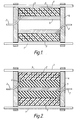
- FIG. 1 a structure for a typical underwater towed array application is shown.
- Longitudinal strain members 1 in the array are used to mount the internal equipment, including the hydrophones.
- a typical hydrophone might be as in the diagram, where the fibre coil 2 is encapsulated in a compressible material 3 and mounted on a rigid former attached to the strain members; the coil assembly is bonded well both to the ends of the bobbin shaped former and to the "axle" 5.
- Longitudinal balancing is achieved by the action of both the ends 4 and the axle 5, although some balancing could be achieved by either of these acting alone.
- the coil, driven symmetrically from within its circumference will always tend to be balanced, since a compressive force on one part will always be counteracted by opposite effects on another part of the coil.
- the axle part 5 of the rigid mount drives the coil in a perpendicular direction and consequently will achieve perpendicular balancing.
- the encapsulant material, and rigid material for the former By suitable choice of encapsulant material, and rigid material for the former, the acoustic sensitivity of the coil can be maintained.
- the encapsulant should be of low bulk modulus, while the former should be of light weight, and have stiffness.
- the rigid former could be made of a low mass alloy or a rigid thermoset material.
- a secondary material 6 is used between the coil 2 and the former 4, 5, of lower bulk modulus than the encapsulant 3.
- the material 6, an example of which is a low modulus epoxy resin, should have a higher compressibility than the encapsulant 3.
- the encapsulant 3 could be rubber or resin epoxy for example.
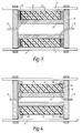
- Figure 4 illustrates an alternative realisation of the concept of Figure 3, in which the ends of the fibre encapsulant 3 are entirely unconstrained and the secondary material is air contained in gap 4c.
- the sensitivity to axial acceleration will now be dependent on the rigidity of the encapsulating material, and a material should be selected which yields a suitable compromise between maximum acoustic sensitivity and minimum acceleration sensitivity.
- the encapsulant 3 is supported on abutments 4a and sealed thereto by suitable means, for example o-rings 4b.
- the encapsulant 3 could be hard rubber, epoxy or polyester for example.
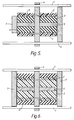
- Figure 5 is a design in which both perpendicular and longitudinal inertial insensitivity is achieved by driving from the centre, both axially and radially via central section 4.
- the acoustic sensitivity is maximised by appropriate choice of a compressible internal material 6 between the "axle" 5 and the encapsulant 3; this may result in the requirement for end caps 7 as shown.
- Two examples of end caps are shown which differ in that the ends of the encapsulant 3 may be either exposed or covered. These prevent static pressure acting via the compressible layer 6 on the inner surface of the encapsulant 3, which would counter the effect of the static pressure on the outer surface of the coil.
- Examples of high compressible materials are air and polyester resin.
- the encapsulant 3 could be hard rubber or a low density polyethylene for example. In the example of Figure 5, fewer layers of fibres 2 would be required to achieve the desired effect than would be the case if the compressible material was not present.
- Figure 6 represents a hydrophone in which the inertial sensitivity is reduced by ensuring the device is mechanically driven from the centre via central section 4.
- the end plates 7 act as piston, transferring pressure to the encapsulated fibre 2, whilst the secondary material 6 allows the encapsulant to expand in the perpendicular direction to an extent dependent upon its properties.
- the secondary material 6, should be a pressure release material i.e. it reflects sound waves in water, examples of which are, air, cork with rubber, and foam.
- the encapsulant material 3 could be soft rubber, or soft epoxy composite.
Description
- The present invention relates to hydrophones and more particularly to inertially insensitive optical fibre hydrophones.
- Like all hydrophones the optical fibre version is subject to inertial or acceleration sensitivity, due to its own mass: that is, it cannot tell whether it is "seeing" an acceleration or a static force such as an acoustic pressure. This sensitivity depends upon the detailed design of the sensor as well as the intrinsic transduction mechanism, and can be reduced by a "balanced" design which nulls the effect of the acceleration, or by appropriate design and choice of materials which renders the design inherently inertially insensitive.
- In a underwater towed array of acoustic sensors, the vibration levels can be very high, and the hydrophone inertial sensitivity needs to be correspondingly low; this applies to accelerations both along and across the array. To achieve this, balanced designs need to be used in general and a variety of methods are used in piezoelectric technology to achieve this. An alternative approach is to provide a reference sensor isolated from the measurand, but held in a fixed position relative to a sensor exposed to the measurand. This enables signals generated due to inertial effects experienced by the reference sensor to be subtracted from those of the exposed sensor. The problem with this type of arrangement is that the reference sensor has to be isolated from the measurand, while still being maintained in a fixed position relative to the exposed sensor. Such a device is disclosed in US Patent 4193130.
- The present invention is concerned with a particular approach to balancing a fibre hydrophone in the longitudinal and/or perpendicular directions, for use in towed arrays and other underwater applications. The invention will be described with particular reference to a towed array, but is also relevant to dunking sonars and sonabuoys.
- In most towed arrays, the hydrophones are mounted from the strain members, which can be two or more. The forcing function causing the unwanted acceleration outputs is applied via these strain members. It is assumed that the hydrophone will be fastened to these strain members, since these are the only structural elements in the array.
- One way of obtaining balancing of a fibre coil, in the longitudinal direction is shown in GB-A-2 189 110. In this arrangement the hydrophone comprises a fibre coil having a mounting flange located midway along its length, such that axial/longitudinal acceleration causes equal and opposite distortions of the fibre on either side of the flange, thus cancelling the effects of axial acceleration. However this does not compensate in the perpendicular direction, and might be difficult to realise as a device with a single fixing. Another example of standard practice in conventional piezo electric type hydrophones is where the piezo stack is attached at each end to plates which are attached to the source of the acceleration; the pressure sensitivity is unbalanced while longitudinal acceleration is balanced.
- An aim of the present invention is to provide some configurations in which some principles similar to those disclosed in GB-A-2 189 110 are used to achieve longitudinal and perpendicular balancing, while preserving acoustic sensitivity.
- According to the present invention there is provided a hydrophone comprising an optical fibre coil embedded in an encapsulant material, a rigid former having an axial part extending inside the coil in an axial direction with respect thereto, and means for attaching the former to strain members by which, in use, the hydrophone is carried, the encapsulant being mounted on the axial part of the former in such a way that inertial forces generated on opposite sides of the coil by the acceleration of the former in a direction perpendicular to the axial part cause opposite effects thereby reducing the inertial sensitivity of the hydrophone.
- Advantageously, the former comprises a central section orientated substantially orthogonal to and supporting said axial portion, wherein the coil comprises two portions positioned on said axial portion to either side of said central section, said central section driving the coil in a longitudinal direction providing longitudinal balancing such as to reduce inertial sensitivity.
- In a preferred embodiment a secondary material having a lower bulk modulus than that of the encapsulant material is positioned between the former and the encapsulant material.
- Embodiments of the present invention will now be described with reference to the accompanying drawings wherein:-
- Figure 1 shows a hydrophone structure for a typical underwater towed array application;
- Figure 2 shows a hydrophone structure employing a secondary material between a coil and a former;
- Figure 3 shows a hydrophone structure where the ends of the coil encapsulant are unconstrained;
- Figure 4 shows an alternative realisation of the hydrophone structure shown in Figure 3;
- Figure 5 shows a hydrophone structure in which inertial insensitivity is achieved by driving from the centre; and
- Figure 6 shows a hydrophone structure in which the acoustic sensitivity is enhanced by different means.
- Referring to Figure 1, a structure for a typical underwater towed array application is shown.
Longitudinal strain members 1 in the array are used to mount the internal equipment, including the hydrophones. A typical hydrophone might be as in the diagram, where thefibre coil 2 is encapsulated in acompressible material 3 and mounted on a rigid former attached to the strain members; the coil assembly is bonded well both to the ends of the bobbin shaped former and to the "axle" 5. Longitudinal balancing is achieved by the action of both theends 4 and theaxle 5, although some balancing could be achieved by either of these acting alone. In the perpendicular direction, it should be noted that the coil, driven symmetrically from within its circumference will always tend to be balanced, since a compressive force on one part will always be counteracted by opposite effects on another part of the coil. - In Figure 1, the
axle part 5 of the rigid mount drives the coil in a perpendicular direction and consequently will achieve perpendicular balancing. By suitable choice of encapsulant material, and rigid material for the former, the acoustic sensitivity of the coil can be maintained. As a generalisation, the encapsulant should be of low bulk modulus, while the former should be of light weight, and have stiffness. The rigid former could be made of a low mass alloy or a rigid thermoset material. A variation of this technique is shown in Figure 2 where asecondary material 6 is used between thecoil 2 and the former 4, 5, of lower bulk modulus than theencapsulant 3. This will increase the acoustic sensitivity whilst probably degrading the acceleration response, (air would be ideal from an acoustic viewpoint, but would not provide adequate coupling for vertical inertial compensation). Thematerial 6, an example of which is a low modulus epoxy resin, should have a higher compressibility than theencapsulant 3. Theencapsulant 3 could be rubber or resin epoxy for example. - Yet another variation is shown in Figure 3, where the ends of the encapsulant are unconstrained, or rather less constrained than in previous examples, and
secondary material 6 is inserted between theformer ends 4 andencapsulant 3. If, in this case, thesecondary material 6 was left out, hydrostatic pressure, acting on the ends would tend to reduce acoustic sensitivity. By a suitable choice ofsecondary material 6 or a secondary structure constraint should be reduced and acoustic sensitivity increased. The relative acceleration sensitivity would be affected by the design and materials used. Examples of secondary materials, which should have a high compressibility, i.e. a low bulk modulus, are air or foamed rubber. Theencapsulant 3 would be rubber or epoxy resin, for example. Further examples of suitable hydrophone designs are given in Figures 4, 5 and 6. - Figure 4 illustrates an alternative realisation of the concept of Figure 3, in which the ends of the
fibre encapsulant 3 are entirely unconstrained and the secondary material is air contained in gap 4c. The sensitivity to axial acceleration will now be dependent on the rigidity of the encapsulating material, and a material should be selected which yields a suitable compromise between maximum acoustic sensitivity and minimum acceleration sensitivity. Theencapsulant 3 is supported on abutments 4a and sealed thereto by suitable means, for example o-rings 4b. Theencapsulant 3 could be hard rubber, epoxy or polyester for example. - Figure 5 is a design in which both perpendicular and longitudinal inertial insensitivity is achieved by driving from the centre, both axially and radially via
central section 4. In the hydrophone illustrated, the acoustic sensitivity is maximised by appropriate choice of a compressibleinternal material 6 between the "axle" 5 and theencapsulant 3; this may result in the requirement forend caps 7 as shown. Two examples of end caps are shown which differ in that the ends of theencapsulant 3 may be either exposed or covered. These prevent static pressure acting via thecompressible layer 6 on the inner surface of theencapsulant 3, which would counter the effect of the static pressure on the outer surface of the coil. Examples of high compressible materials are air and polyester resin. Theencapsulant 3 could be hard rubber or a low density polyethylene for example. In the example of Figure 5, fewer layers offibres 2 would be required to achieve the desired effect than would be the case if the compressible material was not present. - Figure 6 represents a hydrophone in which the inertial sensitivity is reduced by ensuring the device is mechanically driven from the centre via
central section 4. Theend plates 7 act as piston, transferring pressure to theencapsulated fibre 2, whilst thesecondary material 6 allows the encapsulant to expand in the perpendicular direction to an extent dependent upon its properties. Thesecondary material 6, should be a pressure release material i.e. it reflects sound waves in water, examples of which are, air, cork with rubber, and foam. Theencapsulant material 3 could be soft rubber, or soft epoxy composite. - Finally the structure could be driven from a central flange as in GB-A-2 189 110, rather than from an end flange as in the examples above.
- It should be noted that the arrangements illustrated in Figures 1 - 6 do not necessarily represent the only practical approach. Variations may be envisaged within the scope of the claimed invention by those skilled in the art. In particular in Figures 1-5, the "axle" could comprise an open ended tube, allowing cables to be routed along the axis of the assembly. Also various examples of encapsulant, secondary material and rigid former material have been given, but it will be realised that other materials could be suitable.
Claims (12)
- A hydrophone comprising an optical fibre coil (2) embedded in a compressible encapsulant material (3), a rigid former having an axial part (5) extending inside the coil (2) in an axial direction with respect thereto, and means for attaching the former to strain members (1) by which, in use, the hydrophone is carried, the encapsulant (3) being mounted on the axial part (5) of the former in such a way that inertial forces generated on opposite sides of the coil (2) by acceleration of the former in a direction perpendicular to the axial part, cause opposite effects, thereby reducing the inertial sensitivity of the hydrophone.
- A hydrophone as claimed in claim 1, wherein the former further comprises a central section (4) orientated substantially orthogonal to and supporting said axial portion (5), wherein two caps (7) are positioned on said axial portion to either side of said central section (4), said central section (4) driving the coil (2) in a longitudinal direction providing longitudinal balancing of the coil (2) such as to reduce inertial sensitivity.
- A hydrophone as claimed in claim 1, wherein the rigid former is bobbin shaped and comprises an axial portion (5) and end parts (4), the end parts driving the coil (2) in a longitudinal direction providing longitudinal balancing of the coil (2) such as to reduce inertial sensitivity.
- A hydrophone as claimed in claim 1, wherein the former comprises end parts (7) which are remote from the axial portion (5) and act as pistons transferring pressure to the encapsulant material (3).
- A hydrophone as claimed in claim 4, wherein a secondary material (6) having a lower bulk modulus of elasticity than the encapsulant material (3) surrounds surfaces of the encapsulant material (3) not adjacent to the end parts (7).
- A hydrophone as claimed in any one of claims 1 to 3, wherein a secondary material (6) having a lower bulk modulus than that of the encapsulant material (3) is positioned between the former and the encapsulant material (3).
- A hydrophone as claimed in any preceding claim, wherein the rigid former has the properties of low mass and stiffness.
- A hydrophone as claimed in any preceding claim, wherein the rigid former is of a low mass alloy material.
- A hydrophone as claimed in any preceding claim wherein the encapsulant material (3) is bonded to the rigid former.
- A hydrophone as claimed in claim 5 or 6, wherein the encapsulant material (3) is rubber or epoxy resin and the secondary material (6) is an epoxy resin of lower bulk modulus than the encapsulant.
- A hydrophone as claimed in claim 5 or 6, wherein the encapsulant material (3) is rubber or a low density polyethylene and the secondary material (6) is air, foam, cork, an air composition, thermoplastic, epoxy resin or polyester resin.
- A hydrophone as claimed in claim 5 or 6, wherein the encapsulant material (3) is soft rubber or soft epoxy resin and the secondary material (6) is air, cork with rubber, or foam.
Applications Claiming Priority (2)
| Application Number | Priority Date | Filing Date | Title |
|---|---|---|---|
| GB8817256 | 1988-07-20 | ||
| GB8817256A GB2221120B (en) | 1988-07-20 | 1988-07-20 | A hydrophone |
Publications (3)
| Publication Number | Publication Date |
|---|---|
| EP0351990A2 EP0351990A2 (en) | 1990-01-24 |
| EP0351990A3 EP0351990A3 (en) | 1991-11-06 |
| EP0351990B1 true EP0351990B1 (en) | 1994-04-06 |
Family
ID=10640775
Family Applications (1)
| Application Number | Title | Priority Date | Filing Date |
|---|---|---|---|
| EP89306914A Expired - Lifetime EP0351990B1 (en) | 1988-07-20 | 1989-07-07 | A hydrophone |
Country Status (5)
| Country | Link |
|---|---|
| US (1) | US4998226A (en) |
| EP (1) | EP0351990B1 (en) |
| AU (1) | AU623664B2 (en) |
| DE (1) | DE68914354T2 (en) |
| GB (1) | GB2221120B (en) |
Families Citing this family (13)
| Publication number | Priority date | Publication date | Assignee | Title |
|---|---|---|---|---|
| GB9026587D0 (en) * | 1990-12-06 | 1991-04-24 | Marconi Gec Ltd | Improvements relating to optical fibre coil assemblies |
| US5253222A (en) * | 1992-01-28 | 1993-10-12 | Litton Systems, Inc. | Omnidirectional fiber optic hydrophone |
| NO930279D0 (en) * | 1992-01-28 | 1993-01-27 | Litton Systems Inc | CIRCULAR FIBER OPTIC HYDROPHONE |
| GB2312503A (en) * | 1996-04-26 | 1997-10-29 | Marconi Gec Ltd | Two-part balancing coil assembly compensates for vibration |
| US5781510A (en) * | 1997-01-17 | 1998-07-14 | Input/Output, Inc. | Hydrophone housing for a solid marine seismic cable |
| US6188646B1 (en) | 1999-03-29 | 2001-02-13 | Syntron, Inc. | Hydrophone carrier |
| US6498769B1 (en) | 2000-08-04 | 2002-12-24 | Input/Output, Inc. | Method and apparatus for a non-oil-filled towed array with a novel hydrophone design and uniform buoyancy technique |
| CN101598594B (en) * | 2009-06-17 | 2011-08-10 | 中国科学院半导体研究所 | Optical fiber hydrophone towed array protection bracket |
| PT106487A (en) * | 2012-08-03 | 2014-02-03 | Joao Manuel Machado Pinto Germano | AGGLOMERATE PANELS OF EXPANDED CORK WITH OPTICAL FIBER |
| CN110006517A (en) * | 2019-03-26 | 2019-07-12 | 中国船舶重工集团公司第七一五研究所 | Air backing is nonelastic body fiber optic hydrophone unit and processing method |
| CN110006519A (en) * | 2019-03-26 | 2019-07-12 | 中国船舶重工集团公司第七一五研究所 | The air backing fiber optic hydrophone unit of integrated sensitization structure |
| CN110006518A (en) * | 2019-03-26 | 2019-07-12 | 中国船舶重工集团公司第七一五研究所 | The dish-like optical fiber plane hydrophone of vibration cancellation |
| CN112781713A (en) * | 2020-12-25 | 2021-05-11 | 海鹰企业集团有限责任公司 | Pressure balance structure of interference type optical fiber hydrophone |
Family Cites Families (9)
| Publication number | Priority date | Publication date | Assignee | Title |
|---|---|---|---|---|
| US2762032A (en) * | 1954-11-26 | 1956-09-04 | Shell Dev | Seismic hydrophone |
| US2837731A (en) * | 1955-04-19 | 1958-06-03 | Harris Transducer Corp | Hydrophone cable |
| FR1486401A (en) * | 1965-05-22 | 1967-06-30 | Inst Francais Du Petrole | Pressure sensors insensitive to noise |
| US4193130A (en) * | 1978-09-07 | 1980-03-11 | The United States Of America As Represented By The Secretary Of The Navy | Fiber optic hydrophone for use as an underwater electroacoustic standard |
| US4471474A (en) * | 1979-09-28 | 1984-09-11 | Hughes Aircraft Company | Coupled waveguide acousto-optic hydrophone |
| US4405198A (en) * | 1981-08-25 | 1983-09-20 | The United States Of America As Represented By The Secretary Of The Navy | Extended fiber optic sensor using birefringent fibers |
| US4510588A (en) * | 1981-12-22 | 1985-04-09 | Shell Oil Company | Hydrophone cable decoupler |
| JPS60180400A (en) * | 1984-02-28 | 1985-09-14 | Nec Corp | Acoustic transducer |
| GB2189110B (en) * | 1986-03-17 | 1989-11-15 | Plessey Co Plc | Improvements relating to optical fibre hydrophones |
-
1988
- 1988-07-20 GB GB8817256A patent/GB2221120B/en not_active Expired - Lifetime
-
1989
- 1989-07-07 DE DE68914354T patent/DE68914354T2/en not_active Expired - Fee Related
- 1989-07-07 EP EP89306914A patent/EP0351990B1/en not_active Expired - Lifetime
- 1989-07-11 AU AU38009/89A patent/AU623664B2/en not_active Ceased
- 1989-07-18 US US07/381,086 patent/US4998226A/en not_active Expired - Lifetime
Also Published As
| Publication number | Publication date |
|---|---|
| GB2221120B (en) | 1992-07-15 |
| GB8817256D0 (en) | 1988-11-16 |
| DE68914354D1 (en) | 1994-05-11 |
| DE68914354T2 (en) | 1994-07-28 |
| AU623664B2 (en) | 1992-05-21 |
| GB2221120A (en) | 1990-01-24 |
| AU3800989A (en) | 1990-01-25 |
| EP0351990A2 (en) | 1990-01-24 |
| US4998226A (en) | 1991-03-05 |
| EP0351990A3 (en) | 1991-11-06 |
Similar Documents
| Publication | Publication Date | Title |
|---|---|---|
| EP0351990B1 (en) | A hydrophone | |
| CA2552648C (en) | Flexible hydrophone | |
| US5600608A (en) | Hydrophone carrier | |
| US5646470A (en) | Acoustic transducer | |
| US6473365B2 (en) | Supporting structure of hydrophones for towed array sonar system | |
| US7345953B2 (en) | Flextensional vibration sensor | |
| US5825489A (en) | Mandrell based embedded planar fiber-optic interferometric acoustic sensor | |
| US6128251A (en) | Solid marine seismic cable | |
| US4326275A (en) | Directional transducer | |
| EP0098017B1 (en) | End weighted reed sound transducer | |
| US4827459A (en) | High sensitivity accelerometer for crossed dipoles acoustic sensors | |
| EP0456302A2 (en) | Inter-element mounting for stacked piezoelectric transducers | |
| US6151277A (en) | Hydrophone with ferroelectric sensor | |
| US7440644B2 (en) | Optical fibre sensor assembly | |
| US6002649A (en) | Tapered cylinder electro-acoustic transducer with reversed tapered driver | |
| KR102250987B1 (en) | High sensitivity compression type accelerometer and Method for assembling the same | |
| US6111820A (en) | Semi-rigid low-noise interlink for spatially extended hydrophones | |
| US4797863A (en) | Underwater acoustical transducer | |
| AU680489B2 (en) | Hydrophone carrier | |
| RU2679931C1 (en) | Combined vector-scalar receiver | |
| SU1014155A1 (en) | Electroacoustic transducer | |
| US5784341A (en) | Underwater acoustic transmitter for large submersion | |
| GB2256561A (en) | Large area optical fibre hydrophone | |
| JPH0754997B2 (en) | Underwater receiver | |
| GB2272818A (en) | Sonar transducers |
Legal Events
| Date | Code | Title | Description |
|---|---|---|---|
| PUAI | Public reference made under article 153(3) epc to a published international application that has entered the european phase |
Free format text: ORIGINAL CODE: 0009012 |
|
| AK | Designated contracting states |
Kind code of ref document: A2 Designated state(s): DE FR IT SE |
|
| RAP1 | Party data changed (applicant data changed or rights of an application transferred) |
Owner name: GEC-MARCONI LIMITED |
|
| PUAL | Search report despatched |
Free format text: ORIGINAL CODE: 0009013 |
|
| AK | Designated contracting states |
Kind code of ref document: A3 Designated state(s): DE FR IT SE |
|
| 17P | Request for examination filed |
Effective date: 19911012 |
|
| 17Q | First examination report despatched |
Effective date: 19921211 |
|
| GRAA | (expected) grant |
Free format text: ORIGINAL CODE: 0009210 |
|
| AK | Designated contracting states |
Kind code of ref document: B1 Designated state(s): DE FR IT SE |
|
| ITF | It: translation for a ep patent filed |
Owner name: JACOBACCI CASETTA & PERANI S.P.A. |
|
| REF | Corresponds to: |
Ref document number: 68914354 Country of ref document: DE Date of ref document: 19940511 |
|
| ET | Fr: translation filed | ||
| EAL | Se: european patent in force in sweden |
Ref document number: 89306914.6 |
|
| PLBE | No opposition filed within time limit |
Free format text: ORIGINAL CODE: 0009261 |
|
| STAA | Information on the status of an ep patent application or granted ep patent |
Free format text: STATUS: NO OPPOSITION FILED WITHIN TIME LIMIT |
|
| 26N | No opposition filed | ||
| REG | Reference to a national code |
Ref country code: FR Ref legal event code: TP |
|
| PGFP | Annual fee paid to national office [announced via postgrant information from national office to epo] |
Ref country code: DE Payment date: 20070705 Year of fee payment: 19 |
|
| PGFP | Annual fee paid to national office [announced via postgrant information from national office to epo] |
Ref country code: IT Payment date: 20070731 Year of fee payment: 19 Ref country code: SE Payment date: 20070704 Year of fee payment: 19 |
|
| PGFP | Annual fee paid to national office [announced via postgrant information from national office to epo] |
Ref country code: FR Payment date: 20070710 Year of fee payment: 19 |
|
| EUG | Se: european patent has lapsed | ||
| PG25 | Lapsed in a contracting state [announced via postgrant information from national office to epo] |
Ref country code: DE Free format text: LAPSE BECAUSE OF NON-PAYMENT OF DUE FEES Effective date: 20090203 |
|
| REG | Reference to a national code |
Ref country code: FR Ref legal event code: ST Effective date: 20090331 |
|
| PG25 | Lapsed in a contracting state [announced via postgrant information from national office to epo] |
Ref country code: IT Free format text: LAPSE BECAUSE OF NON-PAYMENT OF DUE FEES Effective date: 20080707 Ref country code: FR Free format text: LAPSE BECAUSE OF NON-PAYMENT OF DUE FEES Effective date: 20080731 |
|
| PG25 | Lapsed in a contracting state [announced via postgrant information from national office to epo] |
Ref country code: SE Free format text: LAPSE BECAUSE OF NON-PAYMENT OF DUE FEES Effective date: 20080708 |