EP0351377B1 - Apparatus for welding motor vehicle bodies - Google Patents
Apparatus for welding motor vehicle bodies Download PDFInfo
- Publication number
- EP0351377B1 EP0351377B1 EP89830295A EP89830295A EP0351377B1 EP 0351377 B1 EP0351377 B1 EP 0351377B1 EP 89830295 A EP89830295 A EP 89830295A EP 89830295 A EP89830295 A EP 89830295A EP 0351377 B1 EP0351377 B1 EP 0351377B1
- Authority
- EP
- European Patent Office
- Prior art keywords
- welding
- locating
- gate
- station
- gates
- Prior art date
- Legal status (The legal status is an assumption and is not a legal conclusion. Google has not performed a legal analysis and makes no representation as to the accuracy of the status listed.)
- Expired - Lifetime
Links
- 238000003466 welding Methods 0.000 title claims abstract description 78
- 238000010168 coupling process Methods 0.000 claims description 11
- 238000005859 coupling reaction Methods 0.000 claims description 11
- 230000008878 coupling Effects 0.000 claims description 10
- 230000000694 effects Effects 0.000 description 2
- 239000012530 fluid Substances 0.000 description 2
- 238000005452 bending Methods 0.000 description 1
- 230000005540 biological transmission Effects 0.000 description 1
- 238000004891 communication Methods 0.000 description 1
- 238000010276 construction Methods 0.000 description 1
- 238000009432 framing Methods 0.000 description 1
- 238000003780 insertion Methods 0.000 description 1
- 230000037431 insertion Effects 0.000 description 1
- 238000009434 installation Methods 0.000 description 1
- 238000000034 method Methods 0.000 description 1
Images



Classifications
-
- B—PERFORMING OPERATIONS; TRANSPORTING
- B62—LAND VEHICLES FOR TRAVELLING OTHERWISE THAN ON RAILS
- B62D—MOTOR VEHICLES; TRAILERS
- B62D65/00—Designing, manufacturing, e.g. assembling, facilitating disassembly, or structurally modifying motor vehicles or trailers, not otherwise provided for
- B62D65/02—Joining sub-units or components to, or positioning sub-units or components with respect to, body shell or other sub-units or components
-
- B—PERFORMING OPERATIONS; TRANSPORTING
- B23—MACHINE TOOLS; METAL-WORKING NOT OTHERWISE PROVIDED FOR
- B23K—SOLDERING OR UNSOLDERING; WELDING; CLADDING OR PLATING BY SOLDERING OR WELDING; CUTTING BY APPLYING HEAT LOCALLY, e.g. FLAME CUTTING; WORKING BY LASER BEAM
- B23K37/00—Auxiliary devices or processes, not specially adapted for a procedure covered by only one of the other main groups of this subclass
- B23K37/04—Auxiliary devices or processes, not specially adapted for a procedure covered by only one of the other main groups of this subclass for holding or positioning work
- B23K37/047—Auxiliary devices or processes, not specially adapted for a procedure covered by only one of the other main groups of this subclass for holding or positioning work moving work to adjust its position between soldering, welding or cutting steps
-
- B—PERFORMING OPERATIONS; TRANSPORTING
- B23—MACHINE TOOLS; METAL-WORKING NOT OTHERWISE PROVIDED FOR
- B23P—METAL-WORKING NOT OTHERWISE PROVIDED FOR; COMBINED OPERATIONS; UNIVERSAL MACHINE TOOLS
- B23P2700/00—Indexing scheme relating to the articles being treated, e.g. manufactured, repaired, assembled, connected or other operations covered in the subgroups
- B23P2700/50—Other automobile vehicle parts, i.e. manufactured in assembly lines
-
- Y—GENERAL TAGGING OF NEW TECHNOLOGICAL DEVELOPMENTS; GENERAL TAGGING OF CROSS-SECTIONAL TECHNOLOGIES SPANNING OVER SEVERAL SECTIONS OF THE IPC; TECHNICAL SUBJECTS COVERED BY FORMER USPC CROSS-REFERENCE ART COLLECTIONS [XRACs] AND DIGESTS
- Y10—TECHNICAL SUBJECTS COVERED BY FORMER USPC
- Y10T—TECHNICAL SUBJECTS COVERED BY FORMER US CLASSIFICATION
- Y10T29/00—Metal working
- Y10T29/51—Plural diverse manufacturing apparatus including means for metal shaping or assembling
- Y10T29/5168—Multiple-tool holder
Definitions
- the present invention relates to apparatus for welding loosely pre-assembled motor vehicles bodies, of the type indicated in the pre-characterising portion of claim 1.
- the object of the present invention is to provide an apparatus of the type specified above, which is able to operate on a relatively large number of different body types and which at the same time occupies a reduced space longitudinally of the welding station.
- the invention provides an apparatus having the features set forth in claim 1.
- a corresponding pair of locating gates When a body arrives at the welding station, a corresponding pair of locating gates is brought into the operative position in which the respective locating devices engage the various parts of the body to clamp them in their correct positions of assembly, whilst the welding devices effect a sufficient number of electrical spot welds to provide the structure with a relatively stable configuration.
- the body Upon the completion of such so-called “framing" operation, the body is discharged from the welding station and replaced by a new body to be welded. If the body entering the welding station is of a different type from that welded before, the locating gates previously used in the working position are returned to the respective rotary drums and the latter are rotated so as to bring the two locating gates which correspond to the new type of body to be welded into positions facing the working position.
- the two locating gates to be used are moved transversely away from their positions on the rotary drums, until they are brought into engagement with the body to be welded.
- each locating gate also carries a plurality of welding guns whose electrodes are connected to terminal contacts provided on the locating gate.
- Fixed electrical supply means for the welding guns are provided in correspondence with the working position in the welding station, and include a pair of contacts which can engage the terminal contacts carried by the locating gate when the latter is in its operative position.
- the welding station is also provided with welding robots suspended in raised positions above the working position of the welding station.
- a welding station according to the present invention is generally indicated 1.
- the station 1 comprises a fixed structure which, in the embodiment illustrated, includes two pairs of columns 2 situated at the two sides of a conveyor line 3 for transporting the bodies.
- Each pair of columns 2 arranged on one side of the conveyor line 3 is connected at the top by a longitudinal beam 4.
- the fixed structure is completed by two cross members 5 situated in correspondence with the ends of the longitudinal beams 4 and connecting the upper ends of the columns 2 which are situated on these two sides of the conveyor line 3.
- the central region within the fixed structure described constitutes the working position of the station, in correspondence with which the bodies to be welded are stopped in order to undergo the necessary welding operations.
- the bodies are first loosely assembled and then brought to the welding station 1.
- the loose preassembly can be carried out, for example, by coupling the various sub-units of the body by means of the bending of tongue-like appendages ("toy tabs" in English terminology) on to adjacent parts of the body.
- the station 1 provides for the positioning of the various parts of the body in the correct assembly position and the effecting of a sufficient number of spot welds to provide the structure with relative stability.
- the conveyor line 3 used for bringing the loosely preassembled bodies into the welding station and for carrying the welded bodies away from the welding station and to the subsequent stations (not illustrated) which complete the welding of the body is shown only schematically in the appended drawings. The details of the structure of the line 3 are not illustrated since this structure is of known type and does not fall within the scope of the present invention. Moreover, it is clear that, whilst the appended drawings illustrate schematically a transfer line which passes through the welding station, any alternative solution may be used for transporting the preassembled bodies into the welding station and for transporting the welded bodies away from the welding station. Various possible solutions in this connection are described, for example, in the cited German patent No. 2,810,822.
- the welding station is provided with a plurality of pairs of locating frames or "gates" which are rapidly interchangeable in the operative position and each of which carries a series of locating devices intended to position the body correctly for the execution of the welding operations.
- the positioning devices of each pair of locating side gates are adapted to a specific type of body.
- the present invention particularly concerns a specific technique which can be used to achieve the rapid replacement of the pair of side gates situated in the operative position in order to enable the welding of a different body type.
- the different types of locating gates are arranged on each side of the line 3 on the periphery of a drum 6 which is mounted for rotation about an axis 7 parallel to the length of the body situated in the welding station.
- the two rotary drums 6 face the working position 1a in the welding station.
- each rotary drum 6 has four faces each carrying a locating gate 8 of a respective type.
- Each locating gate 8 comprises, in known manner, a substantially frame-like support structure 8a ( Figures 11, 12, 13) having its longer sides 8b directed longitudinally and two intermediate cross members 8d parallel to the shorter sides 8c.
- Locating and clamping devices 9 are fixed to the support structure 8a. The structure of the devices 9 is not shown in detail since it is of known type and does not fall within the scope of the present invention. The purpose of the clamping devices 9 is to position the various parts of the loosely preassembled body correctly and to clamp them in that position during the welding.
- each locating gate 8 is also provided with a series of welding guns 10 for the electrical spot welding of the body ( Figures 11, 12, 13), each welding gun 10 comprising two electrodes 10a( Figure 13) carried by the jaws of the gun and being provided with an actuator cylinder 12 for operating its jaws.
- each welding gun 10 comprising two electrodes 10a( Figure 13) carried by the jaws of the gun and being provided with an actuator cylinder 12 for operating its jaws.
- the means for the electrical supply of the electrodes of the welding guns and for the supply of fluid to the actuator cylinders of the guns will be described in detail below.
- Each drum 6 is supported for rotation about the axis 7 by two columns 13, one of which has an associated electric operating motor 14 with a reduction device.
- the electric motor 14 is operated to rotate the rotary drum 6 and position the locating gate 8 corresponding to the type of body to be welded so that it faces the working position. Once this positioning has been effected, the locating gate to be used is removed (in the manner which will be described in detail below) from the rotary drum and brought adjacent the body to be welded so as to enable the clamping devices 9 and the welding devices 10 to engage the body.
- FIG 4 shows the welding station in the condition in which two locating gates have been removed from the rotary drums 6 and brought into engagement with a body to be welded.
- Each locating gate is provided, on its face which faces the rotary drum, with a plurality of coupling pins 15 which enable the gate 8 to be coupled to the rotary drum 6.
- a locating gate 8 is situated in contact with the respective face of the rotary drum 6, each of the pins 15 is housed in a bush 16 mounted in a through-hole 17 formed in the wall 6a of the rotary drum.
- the clamping of the locating gate 8 to the rotary drum 6 is achieved by the engagement of a wedge 18, driven by an actuator cylinder (not visible in the drawings) mounted within the rotary drum 6, in a transverse hole 19 in each coupling pin 15 (see Figure 7).
- a slide device 20 is provided on each side of the welding station for moving the locating gate 8 which faces the working position between the position in which it is coupled to the rotary drum 6 and its operative position adjacent the body to be welded.
- Each device 20 has a portal structure with an upper cross member 21 and two lateral legs 22 (Figure 5).
- the legs 22 are provided with wheels 23 ( Figures 4, 5) which engage two lateral tracks defined by two I-sections 24 supported at their ends by the side members 4 and by columns 25 ( Figures 1, 4).
- the upper faces of the two sections 24 carry two racks 26 on which roll two ring gears 27 supported for rotation by the structure 20 and rotated, through shafts 28 arranged on a common axis along the cross member 21, by a central electric motor 29 and a reduction device 30 with two outputs (Figure 5).
- the operation of the motor 29 causes the rotation of the toothed columns 27 and the consequent movement of the structure 20 with the motor 29 and its transmission in a direction transverse the longitudinal direction of the welding station.
- the two vertical sides of each gate 8 have a pair of vertically spaced holes 31 (Figure 6), each of which has a bush 32 associated therewith.
- Each of the two legs 22 of the structure 20 has a pair of actuator cylinders 33 which cause the insertion of coupling pins 34 ( Figure 6) into the bushes 32 and the consequent coupling of the gate 8 to the device 20.
- the locating gate 8 which faces the working position of the welding station is situated in the position in which it is coupled to the respective rotary frame 6, it is picked up by the device 20 firstly by the positioning of the device 20 in correspondence with the gate 8 to cause the engagement of the pins 34 in the bushes 32 of the gate 8 by the operation of the actuator cylinders 33, and then by the disengagement of the wedges 18 from the coupling pins 15 which lock the gate 8 to the rotary drum.
- the gate 8 can be moved transversely by the operation of the motor 29 until the gate 8 is brought to the operative position ( Figure 4) in which the clamping tools 9 and the welding guns 10 can engage the body to be welded.
- the gate 8 reaches its operative position, its lower edge rises on rollers 34 with horizontal axes ( Figure 3, Figure 8) which ensure the accuracy of the vertical positioning of the gate.
- the accuracy of the horizontal positioning of the gate 8 is ensured by the engagement of the lower arm of the gate against a support wall 35 and by its clamping against this wall by means of a lever 36 ( Figure 8) which is operated by an actuator cylinder 37 and is pivotable about an axis 38.
- the pipes for the supply of fluid to the actuator cylinders of the welding guns which are situated in the hollow structure of the gate 8, are put into communication with a fluid-supply source by means of a quick-coupling connector 39 which is raised automatically until it mates with a corresponding part provided in the locating gate 8.
- a quick-coupling connector 39 which is raised automatically until it mates with a corresponding part provided in the locating gate 8.
- the electrical supply of the welding guns 10 is achieved ( Figure 10) by means of two separate electrical circuits which are connected to two pairs of terminals 40, 41 ( Figure 10, Figure 3) provided in the lower part of the gate 8.
- Each of the terminals 40, 41 is engaged - when the gate 8 is in its operative position - by a clamp 42 operated by an actuator cylinder 43 ( Figure 9), the two clamps 42 associated with each pair of terminals 40, 41 being connected in turn to the two terminals of an electrical supply transformer 44 ( Figure 9). All the welding guns of each electrical circuit are therefore supplied by the same fixed electrical transformer.
- each of the robots - generally indicated 45 - has a head 46 carried by a slide 47 which can slide vertically relative to a further slide 48 which slides horizontally on a bridge 49 whose ends are mounted for sliding on two tracks 50 provided on the side members 4 of the welding station ( Figures 1, 4).
- Each of the three axes of the robot is controlled by a respective electric operating motor.
- the structure of the robots is not described in detail, however, since it is of known type.
- the conveyor line 3 brings successive bodies 51 to be welded to the working position in the welding station 1 with a stepwise movement.
- the bodies arrive at the welding station in a loosely preassembled condition.
- the rotary drums 6 are already arranged with the locating gates of the type corresponding to the type of body to be welded in position facing the working position 1a. If the gate 8 is still attached to the rotary drum 6, the device 20 provided on each side of the station picks up the gate in the manner described above and places it in the operative position.
- the various clamping devices engage the body to position its various elements accurately after which the welding guns 10 carried by the locating gates 8 and the welding guns 46 carried by the robots 45 come into operation to effect the welding of the body.
- the clamping devices 9 open (as do the clamping levers 36) and the devices 20 retract the gates to enable the discharge of the welded body from the welding station and the entry of a new body to be welded. If the body arriving at the station is of the same type as that welded previously, the structures 20 do not return the gates 8 to the rotary drums but leave them in an intermediate waiting position and then, once the new body to be welded has reached the station, return them to the operative position.
- the locating gates 8 used previously are placed on the respective rotary drums and the latter are rotated until two location gates which correspond to the new type of body to be welded are brought into position facing the working position.
- the devices 20 take the two frames 8 from the rotary drums and place them in the operative position as soon as the new body to be welded has reached the new working position.
- the welding station according to the invention enables four different types of body to be operated on and at the same time occupies a very limited space longitudinally of the installation.
- rotary drums 6 with a corresponding number of faces are provided.
Landscapes
- Engineering & Computer Science (AREA)
- Mechanical Engineering (AREA)
- Combustion & Propulsion (AREA)
- Optics & Photonics (AREA)
- Manufacturing & Machinery (AREA)
- Chemical & Material Sciences (AREA)
- Physics & Mathematics (AREA)
- Transportation (AREA)
- Resistance Welding (AREA)
- Automobile Manufacture Line, Endless Track Vehicle, Trailer (AREA)
- Lining Or Joining Of Plastics Or The Like (AREA)
- Automatic Assembly (AREA)
- Rollers For Roller Conveyors For Transfer (AREA)
- Pressure Welding/Diffusion-Bonding (AREA)
Abstract
Description
- The present invention relates to apparatus for welding loosely pre-assembled motor vehicles bodies, of the type indicated in the pre-characterising portion of claim 1.
- An apparatus of this type is described and illustrated in document DE-A-3 414 387.
- The object of the present invention is to provide an apparatus of the type specified above, which is able to operate on a relatively large number of different body types and which at the same time occupies a reduced space longitudinally of the welding station.
- In order to achieve this object, the invention provides an apparatus having the features set forth in claim 1.
- When a body arrives at the welding station, a corresponding pair of locating gates is brought into the operative position in which the respective locating devices engage the various parts of the body to clamp them in their correct positions of assembly, whilst the welding devices effect a sufficient number of electrical spot welds to provide the structure with a relatively stable configuration. Upon the completion of such so-called "framing" operation, the body is discharged from the welding station and replaced by a new body to be welded. If the body entering the welding station is of a different type from that welded before, the locating gates previously used in the working position are returned to the respective rotary drums and the latter are rotated so as to bring the two locating gates which correspond to the new type of body to be welded into positions facing the working position. When the rotation has been carried out, the two locating gates to be used are moved transversely away from their positions on the rotary drums, until they are brought into engagement with the body to be welded.
- Moreover, in the preferred embodiment, each locating gate also carries a plurality of welding guns whose electrodes are connected to terminal contacts provided on the locating gate. Fixed electrical supply means for the welding guns are provided in correspondence with the working position in the welding station, and include a pair of contacts which can engage the terminal contacts carried by the locating gate when the latter is in its operative position. Preferably, the welding station is also provided with welding robots suspended in raised positions above the working position of the welding station.
- Further characteristics and advantages of the invention will become clear from the description which follows with reference to the appended drawings, in which:
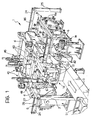
- Figure 1 is a schematic perspective view of welding apparatus according to the invention,
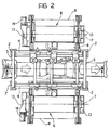
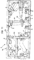
- Figure 2 is a schematic plan view of the apparatus of Figure 1,
- Figure 3 is a section taken on the line III-III of Figure 2,
- Figure 4 is a section taken on the line IV-IV of Figure 2,
- Figure 5 is a section taken on the line V-V of Figure 4,
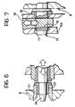
- Figure 6 is a section of the detail indicated by the arrow VI in Figure 5, on an enlarged scale,
- Figure 7 is a section of the detail indicated by the arrow VII of Figure 4, on an enlarged scale,
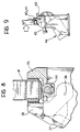
- Figure 8 is a section of the detail indicated by the arrow VIII of Figure 4, on an enlarged scale,
- Figure 9 is a view of the detail indicated by the arrow IX of Figure 3, on an enlarged scale,
- Figure 10 is a schematic view of the electrical supply system of the welding guns situated on a forming frame, and
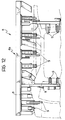
- Figures 11, 12 and 13 are a schematic side view, a schematic plan view and a schematic front view of a forming frame engaged with a motor vehicle body.
- In Figures 1 to 4, a welding station according to the present invention is generally indicated 1. The station 1 comprises a fixed structure which, in the embodiment illustrated, includes two pairs of
columns 2 situated at the two sides of a conveyor line 3 for transporting the bodies. Each pair ofcolumns 2 arranged on one side of the conveyor line 3 is connected at the top by alongitudinal beam 4. The fixed structure is completed by twocross members 5 situated in correspondence with the ends of thelongitudinal beams 4 and connecting the upper ends of thecolumns 2 which are situated on these two sides of the conveyor line 3. - The central region within the fixed structure described constitutes the working position of the station, in correspondence with which the bodies to be welded are stopped in order to undergo the necessary welding operations.
- According to the prior art of the same Applicant's German patent No. 2,810,822, the bodies are first loosely assembled and then brought to the welding station 1. The loose preassembly can be carried out, for example, by coupling the various sub-units of the body by means of the bending of tongue-like appendages ("toy tabs" in English terminology) on to adjacent parts of the body. Still according to the prior art described above, the station 1 provides for the positioning of the various parts of the body in the correct assembly position and the effecting of a sufficient number of spot welds to provide the structure with relative stability. The conveyor line 3 used for bringing the loosely preassembled bodies into the welding station and for carrying the welded bodies away from the welding station and to the subsequent stations (not illustrated) which complete the welding of the body is shown only schematically in the appended drawings. The details of the structure of the line 3 are not illustrated since this structure is of known type and does not fall within the scope of the present invention. Moreover, it is clear that, whilst the appended drawings illustrate schematically a transfer line which passes through the welding station, any alternative solution may be used for transporting the preassembled bodies into the welding station and for transporting the welded bodies away from the welding station. Various possible solutions in this connection are described, for example, in the cited German patent No. 2,810,822.
- Again according to the prior art of the above patent, the welding station is provided with a plurality of pairs of locating frames or "gates" which are rapidly interchangeable in the operative position and each of which carries a series of locating devices intended to position the body correctly for the execution of the welding operations. The positioning devices of each pair of locating side gates are adapted to a specific type of body. The present invention particularly concerns a specific technique which can be used to achieve the rapid replacement of the pair of side gates situated in the operative position in order to enable the welding of a different body type.
- In the device according to the invention, the different types of locating gates are arranged on each side of the line 3 on the periphery of a
drum 6 which is mounted for rotation about anaxis 7 parallel to the length of the body situated in the welding station. - In the preferred embodiment illustrated in the drawings, the two
rotary drums 6 face the working position 1a in the welding station. - In the embodiment illustrated, each
rotary drum 6 has four faces each carrying a locatinggate 8 of a respective type. Each locatinggate 8 comprises, in known manner, a substantially frame-like support structure 8a (Figures 11, 12, 13) having itslonger sides 8b directed longitudinally and twointermediate cross members 8d parallel to theshorter sides 8c. Naturally, the particular structure of theframe 8 which is illustrated in the appended drawings is given only by way of example. Locating and clampingdevices 9 are fixed to thesupport structure 8a. The structure of thedevices 9 is not shown in detail since it is of known type and does not fall within the scope of the present invention. The purpose of theclamping devices 9 is to position the various parts of the loosely preassembled body correctly and to clamp them in that position during the welding. The arrangement and shape of thedevices 9 depend on the geometric shape of the body to be welded. In the preferred embodiment illustrated, each locatinggate 8 is also provided with a series ofwelding guns 10 for the electrical spot welding of the body (Figures 11, 12, 13), eachwelding gun 10 comprising twoelectrodes 10a(Figure 13) carried by the jaws of the gun and being provided with anactuator cylinder 12 for operating its jaws. The means for the electrical supply of the electrodes of the welding guns and for the supply of fluid to the actuator cylinders of the guns will be described in detail below. - Each
drum 6 is supported for rotation about theaxis 7 by twocolumns 13, one of which has an associatedelectric operating motor 14 with a reduction device. Theelectric motor 14 is operated to rotate therotary drum 6 and position the locatinggate 8 corresponding to the type of body to be welded so that it faces the working position. Once this positioning has been effected, the locating gate to be used is removed (in the manner which will be described in detail below) from the rotary drum and brought adjacent the body to be welded so as to enable theclamping devices 9 and thewelding devices 10 to engage the body. - Figure 4 shows the welding station in the condition in which two locating gates have been removed from the
rotary drums 6 and brought into engagement with a body to be welded. Each locating gate is provided, on its face which faces the rotary drum, with a plurality ofcoupling pins 15 which enable thegate 8 to be coupled to therotary drum 6. As shown in detail in Figure 7, when a locatinggate 8 is situated in contact with the respective face of therotary drum 6, each of thepins 15 is housed in abush 16 mounted in a through-hole 17 formed in thewall 6a of the rotary drum. The clamping of the locatinggate 8 to therotary drum 6 is achieved by the engagement of awedge 18, driven by an actuator cylinder (not visible in the drawings) mounted within therotary drum 6, in atransverse hole 19 in each coupling pin 15 (see Figure 7). - In the appended drawings, only the locating
gates 8 which are situated in the operative position in correspondence with the working position of the welding station are shown in detail, whilst the rest of the locating gates situated on the rotary drum are shown schematically in broken outline. - A
slide device 20 is provided on each side of the welding station for moving the locatinggate 8 which faces the working position between the position in which it is coupled to therotary drum 6 and its operative position adjacent the body to be welded. Eachdevice 20 has a portal structure with an upper cross member 21 and two lateral legs 22 (Figure 5). Thelegs 22 are provided with wheels 23 (Figures 4, 5) which engage two lateral tracks defined by two I-sections 24 supported at their ends by theside members 4 and by columns 25 (Figures 1, 4). - The upper faces of the two
sections 24 carry tworacks 26 on which roll tworing gears 27 supported for rotation by thestructure 20 and rotated, throughshafts 28 arranged on a common axis along the cross member 21, by a centralelectric motor 29 and areduction device 30 with two outputs (Figure 5). The operation of themotor 29 causes the rotation of thetoothed columns 27 and the consequent movement of thestructure 20 with themotor 29 and its transmission in a direction transverse the longitudinal direction of the welding station. In order to enable the coupling of a locatinggate 8 to thedevice 20, the two vertical sides of eachgate 8 have a pair of vertically spaced holes 31 (Figure 6), each of which has abush 32 associated therewith. Each of the twolegs 22 of thestructure 20 has a pair ofactuator cylinders 33 which cause the insertion of coupling pins 34 (Figure 6) into thebushes 32 and the consequent coupling of thegate 8 to thedevice 20. On the assumption that the locatinggate 8 which faces the working position of the welding station is situated in the position in which it is coupled to the respectiverotary frame 6, it is picked up by thedevice 20 firstly by the positioning of thedevice 20 in correspondence with thegate 8 to cause the engagement of thepins 34 in thebushes 32 of thegate 8 by the operation of theactuator cylinders 33, and then by the disengagement of thewedges 18 from the coupling pins 15 which lock thegate 8 to the rotary drum. Once thegate 8 has been loaded onto thedevice 20, the latter can be moved transversely by the operation of themotor 29 until thegate 8 is brought to the operative position (Figure 4) in which theclamping tools 9 and thewelding guns 10 can engage the body to be welded. When thegate 8 reaches its operative position, its lower edge rises onrollers 34 with horizontal axes (Figure 3, Figure 8) which ensure the accuracy of the vertical positioning of the gate. At the same time, the accuracy of the horizontal positioning of thegate 8 is ensured by the engagement of the lower arm of the gate against asupport wall 35 and by its clamping against this wall by means of a lever 36 (Figure 8) which is operated by anactuator cylinder 37 and is pivotable about anaxis 38. When thelever 36 is in the operative position illustrated in Figure 8, it comes into engagement with thegate 8 on the side opposite that which is in contact with thesupport wall 35 so as to clamp the gate against the latter. - When the
gate 8 is in its operative position, the pipes for the supply of fluid to the actuator cylinders of the welding guns, which are situated in the hollow structure of thegate 8, are put into communication with a fluid-supply source by means of a quick-coupling connector 39 which is raised automatically until it mates with a corresponding part provided in the locatinggate 8. The details of this connector are not illustrated since they are of known type. In the embodiment illustrated, the electrical supply of thewelding guns 10 is achieved (Figure 10) by means of two separate electrical circuits which are connected to two pairs ofterminals 40, 41 (Figure 10, Figure 3) provided in the lower part of thegate 8. Each of theterminals gate 8 is in its operative position - by aclamp 42 operated by an actuator cylinder 43 (Figure 9), the twoclamps 42 associated with each pair ofterminals - Finally, three cartesian robots are provided in the upper part of the welding station and carry the same number of welding guns which cooperate with the welding guns carried by the forming
gates 8 in the operative position so as to carry out the welding of the body which is in the station. Each of the robots - generally indicated 45 - has ahead 46 carried by aslide 47 which can slide vertically relative to afurther slide 48 which slides horizontally on abridge 49 whose ends are mounted for sliding on twotracks 50 provided on theside members 4 of the welding station (Figures 1, 4). Each of the three axes of the robot is controlled by a respective electric operating motor. The structure of the robots is not described in detail, however, since it is of known type. - The operation of the system described above is as follows:
the conveyor line 3 bringssuccessive bodies 51 to be welded to the working position in the welding station 1 with a stepwise movement. As already indicated, the bodies arrive at the welding station in a loosely preassembled condition. When anew body 51 arrives and stops in the welding station, therotary drums 6 are already arranged with the locating gates of the type corresponding to the type of body to be welded in position facing the working position 1a. If thegate 8 is still attached to therotary drum 6, thedevice 20 provided on each side of the station picks up the gate in the manner described above and places it in the operative position. In this position, the various clamping devices engage the body to position its various elements accurately after which thewelding guns 10 carried by the locatinggates 8 and thewelding guns 46 carried by therobots 45 come into operation to effect the welding of the body. When the welding is completed, theclamping devices 9 open (as do the clamping levers 36) and thedevices 20 retract the gates to enable the discharge of the welded body from the welding station and the entry of a new body to be welded. If the body arriving at the station is of the same type as that welded previously, thestructures 20 do not return thegates 8 to the rotary drums but leave them in an intermediate waiting position and then, once the new body to be welded has reached the station, return them to the operative position. If the new body to be welded is of a different type from that welded previously, the locatinggates 8 used previously are placed on the respective rotary drums and the latter are rotated until two location gates which correspond to the new type of body to be welded are brought into position facing the working position. Thedevices 20 take the twoframes 8 from the rotary drums and place them in the operative position as soon as the new body to be welded has reached the new working position. - As can be seen from the above description, the welding station according to the invention enables four different types of body to be operated on and at the same time occupies a very limited space longitudinally of the installation. Obviously, when the number of models to be operated on is other than four,
rotary drums 6 with a corresponding number of faces are provided. - Naturally, the principle of the invention remaining the same, the forms of embodiment and details of construction may be varied, within the scope of the appended claims, with respect to those described and illustrated purely by way of non-limiting example.
Claims (7)
- Apparatus for welding loosely preassembled motor vehicle bodies, comprising:
a station for forming and welding the body (1),
a conveyor line (3) for transporting the loosely preassembled bodies through the station (1),
at least two pairs of locating gates (8) situated at the two sides of the station (1), each pair of locating gates (8) being provided with locating devices (9) engageable with the body (51) and adapted to the specific geometric shape of a particular type of body,
gate conveyor means for bringing a pair of locating gates (8) corresponding to the type of body to be welded into correspondence with a working position (1a) in the welding station, and
at least one welding device (10) for welding the body in the welding station,
said gate conveyor means including two drum members (6) arranged at the two sides of the station (1) and rotatable about respective axes (7) parallel to the length of the body in the welding station, each drum member (6) supporting a plurality of locating gates (8) suitable for different types of body,
characterised in that with each drum member (6) there are associated means (15, 17, 18) for holding the respective locating gates (8) in fixed positions and orientations relative to the drum member (6) during rotation thereof, said apparatus further including means for separating completely a locating gate from its drum member (6) when the latter is on rest and moving it transversely with respect to the conveyor line (3) to an operative position adjacent the body to be welded and vice versa to return the locating gate (8) from the operative position to the drum member (6). - Apparatus according to Claim 1, wherein each locating gate carries a plurality of welding guns (10) whose electrodes (10a) are connected to terminal contacts (40, 41) provided on the gate (8), and wherein fixed electrical supply means (44) for the welding guns (10) are provided in correspondence with the working position (1a) of the welding station (1), characterised in that said supply means (44) include a pair of clamp contacts (42) which can engage terminal contacts (40, 41) carried by the forming frame (8).
- Apparatus according to Claim 1, characterised in that each rotary frame has a polygonal cross-section and carries a locating gate (8) on each of its faces.
- Apparatus according to Claim 1, characterised in that the means for moving the locating gate (8) transversely between the rotary drum (6) and the operative position comprise a portal structure (20) which is guided transversely on the fixed structure of the welding station and has lateral legs (22) provided with coupling pins (34) which are adapted to engage lateral holes (31) provided in the ends of each locating gate (8).
- Apparatus according to Claim 1, characterised in that each locating gate has, on its face which faces the respective rotary drum (6), a plurality of coupling pins (15) which are intended to be housed in corresponding holes (17) in the rotary drum(6) and locked in the holes by means of transverse wedges (18) adapted to engage through-holes (19) formed in the coupling pins (15).
- Apparatus according to Claim 1, characterised in that the top of the fixed structure of the welding station supports a plurality of cartesian robots (45) carrying welding guns.
- Apparatus according to Claim 4, characterised in that means are provided for clamping each locating gate (8) in the operative position in order to ensure the correct positioning of the gate.
Priority Applications (1)
| Application Number | Priority Date | Filing Date | Title |
|---|---|---|---|
| AT89830295T ATE91939T1 (en) | 1988-07-13 | 1989-06-27 | DEVICE FOR WELDING MOTOR CAR BODY. |
Applications Claiming Priority (2)
| Application Number | Priority Date | Filing Date | Title |
|---|---|---|---|
| IT67661/88A IT1223690B (en) | 1988-07-13 | 1988-07-13 | DEVICE FOR THE WELDING OF MOTOR VEHICLE BODIES |
| IT6766188 | 1988-07-13 |
Publications (3)
| Publication Number | Publication Date |
|---|---|
| EP0351377A2 EP0351377A2 (en) | 1990-01-17 |
| EP0351377A3 EP0351377A3 (en) | 1991-01-09 |
| EP0351377B1 true EP0351377B1 (en) | 1993-07-28 |
Family
ID=11304311
Family Applications (1)
| Application Number | Title | Priority Date | Filing Date |
|---|---|---|---|
| EP89830295A Expired - Lifetime EP0351377B1 (en) | 1988-07-13 | 1989-06-27 | Apparatus for welding motor vehicle bodies |
Country Status (11)
| Country | Link |
|---|---|
| US (1) | US4905884A (en) |
| EP (1) | EP0351377B1 (en) |
| JP (1) | JP2668136B2 (en) |
| AT (1) | ATE91939T1 (en) |
| BR (1) | BR8903211A (en) |
| CA (1) | CA1313586C (en) |
| DE (2) | DE8812396U1 (en) |
| ES (1) | ES2043103T3 (en) |
| IT (1) | IT1223690B (en) |
| RU (1) | RU1831417C (en) |
| UA (1) | UA12330A (en) |
Cited By (2)
| Publication number | Priority date | Publication date | Assignee | Title |
|---|---|---|---|---|
| DE10151257B4 (en) * | 2001-10-17 | 2005-12-22 | Kuka Schweissanlagen Gmbh | Method for connecting body parts and framing station |
| DE102012015392A1 (en) | 2012-08-03 | 2014-05-15 | Daimler Ag | Rough construction station for the manufacture of car body shell construction and method for operating a shell construction station |
Families Citing this family (42)
| Publication number | Priority date | Publication date | Assignee | Title |
|---|---|---|---|---|
| IT1173481B (en) * | 1984-03-26 | 1987-06-24 | Rosa Gaetano Di | AUTOMATIC SYSTEM FOR THE ASSEMBLY AND WELDING OF MOTOR VEHICLE BODIES, EQUIPPED WITH A VERY HIGH PRODUCTION RHYTHM, WHICH CAN BE MAINTAINED EVEN IN CONCOMITATION OF THE CHANGE OF THE MODEL IN LINE AND THEREFORE OF THE CHANGE OF CONFORMERS |
| IT1226104B (en) * | 1988-07-07 | 1990-12-10 | Fata Europ Group | IMPROVED SYSTEM EQUIPPED WITH ROTARY GROUPS OF EQUIPMENT FOR WELDING VEHICLE BODIES IN A SINGLE WORKING STATION. |
| US5011068A (en) * | 1989-12-05 | 1991-04-30 | Progressive Tool & Industries Co. | Automotive body framing system |
| US5111988A (en) * | 1990-04-16 | 1992-05-12 | Saturn Corporation | Flexible automated body assembly system and method |
| FR2665094A1 (en) * | 1990-07-24 | 1992-01-31 | Sciaky Ind Sa | INSTALLATION FOR THE REALIZATION OF BODIES OF MOTOR VEHICLES. |
| DE9105490U1 (en) * | 1991-05-03 | 1992-09-10 | KUKA Schweissanlagen GmbH, 86165 Augsburg | Processing station for workpieces, especially vehicle bodies in a transfer line |
| IT1249980B (en) * | 1991-08-07 | 1995-03-30 | Comau Spa | DEVICE FOR THE WELDING OF STRUCTURES, SUCH AS BODIES OF MOTOR VEHICLES OR PARTS OF THEM, MADE UP OF ELEMENTS OF PRINTED SHEET METAL ASSEMBLED PRELIMINARILY AMONG THEM IN A LABULAR WAY. |
| DE9209686U1 (en) * | 1992-07-15 | 1992-09-10 | KUKA Schweissanlagen GmbH, 86165 Augsburg | Processing station for vehicle bodies in a transfer line |
| DE9210396U1 (en) * | 1992-08-04 | 1993-12-02 | Kuka Schweißanlagen + Roboter GmbH, 86165 Augsburg | Processing station for vehicle bodies in a transfer line |
| DE9211841U1 (en) * | 1992-09-02 | 1994-01-13 | KUKA Schweissanlagen GmbH, 86165 Augsburg | Processing station for vehicle bodies in a transfer line |
| GB2273083B (en) * | 1992-12-01 | 1995-10-04 | Honda Motor Co Ltd | Apparatus for assembling motor vehicle body |
| US5409158A (en) * | 1993-07-08 | 1995-04-25 | Progressive Tool & Industries Company | Automobile framing system |
| US5427300A (en) * | 1994-03-22 | 1995-06-27 | Progressive Tool & Industries Co. | Apparatus for framing vehicle bodies |
| DE4418755A1 (en) * | 1994-05-28 | 1995-11-30 | Kuka Schweissanlagen & Roboter | Process and device for the mfr. of vehicle bodies within framed cages |
| US5560535A (en) * | 1995-03-30 | 1996-10-01 | Western Atlas, Inc. | Flexible body framing system |
| DE19601427A1 (en) * | 1996-01-17 | 1997-07-24 | Thyssen Industrie | Device for fixing of body sheets on car structure |
| IT1288733B1 (en) * | 1996-10-08 | 1998-09-24 | Comau Spa | DEVICE FOR POINT WELDING OF STRUCTURES CONSISTING OF METALLIC ELEMENTS, IN PARTICULAR BODIES OF MOTOR VEHICLES OR THEIR |
| US6193142B1 (en) * | 1996-12-25 | 2001-02-27 | Nissan Motor Co., Ltd. | Assembling apparatus assembling body side of automotive vehicle and assembling method thereof |
| CA2282571A1 (en) * | 1997-03-22 | 1998-10-01 | Thyssen Industrie Ag | Device and method for feeding, clamping and processing, particularly for geometric welding of automobile body components in a work station |
| DE19818304A1 (en) * | 1997-05-16 | 1998-11-19 | Voest Alpine Transport Und Mon | Positioning and assembling device for vehicle bodywork parts |
| EP0933161B1 (en) * | 1998-02-03 | 2001-04-04 | COMAU S.p.A. | Device for assembling motor-vehicle bodies by spot-welding |
| US6089440A (en) * | 1998-07-07 | 2000-07-18 | Chrysler Corporation | Adjustable vehicle assembly tool |
| US6173881B1 (en) | 1998-11-11 | 2001-01-16 | Progressive Tool & Industries Company | Car body assembly and welding station with reciprocal gate-supporting system |
| US6073330A (en) * | 1999-03-29 | 2000-06-13 | Daimlerchrysler Corporation | Precision indexing of a turntable used in a hinge-positioner fixture |
| JP3663984B2 (en) * | 1999-08-06 | 2005-06-22 | 日産自動車株式会社 | Body assembly method and body assembly apparatus |
| FR2799428B1 (en) | 1999-10-11 | 2001-12-21 | Abb Body In White | MEANS OF HOLDING TWO PIECES IN POSITION RELATIVE TO THE OTHER |
| US6271496B1 (en) | 1999-12-20 | 2001-08-07 | Bryan W. Domschot | Modular welding machine |
| US6932263B2 (en) * | 2002-04-08 | 2005-08-23 | Progressive Tool & Industries Co. | Vehicle framing system for plurality of vehicle body styles |
| ITTO20050053A1 (en) | 2005-01-31 | 2006-08-01 | Comau Spa | IMPROVEMENT TO THE ASSEMBLY SYSTEMS BY WELDING METAL SHEET STRUCTURES, IN PARTICULAR BODIES OF MOTOR VEHICLES OR THEIR SUBGROUPS |
| DE102009034066A1 (en) | 2009-07-22 | 2011-01-27 | Volkswagen Ag | Device for producing motor vehicle body parts |
| CN102837138B (en) * | 2012-08-13 | 2014-12-31 | 广州明珞汽车装备有限公司 | Collinear flexible head splicer suitable for multiple vehicle types |
| CN102873488B (en) * | 2012-09-14 | 2015-03-11 | 迈赫机器人自动化股份有限公司 | Total tailored welding clamp for multi-vehicle automobile bodies |
| CN103128469B (en) * | 2013-02-28 | 2015-11-11 | 长城汽车股份有限公司 | System and method for splicing side body and lower part of vehicle body |
| CN104384695A (en) * | 2014-10-21 | 2015-03-04 | 上海思尔特机器人科技有限公司 | Robot automatic welding system for car body |
| CN105149849B (en) * | 2015-10-14 | 2017-04-12 | 武汉瑞松北斗汽车装备有限公司 | Three-way non-polar support mechanism for multi-vehicle-type passive trolley |
| CN105127651A (en) * | 2015-10-26 | 2015-12-09 | 上海晓奥享荣汽车工业装备有限公司 | Vehicle body welding assembly capable of being automatically switched |
| US20170291296A1 (en) * | 2016-04-12 | 2017-10-12 | Ascent Aerospace | High precision work piece processing system |
| CN106899151B (en) * | 2016-08-04 | 2023-08-29 | 湖南佳林智能装备有限公司 | Intelligent assembly equipment for motor clamp spring magnetic shoe stator shell |
| CN106378557B (en) * | 2016-11-16 | 2018-02-16 | 郑州日产汽车有限公司 | Flexible Production line suitable for vehicle side production |
| CN106584002B (en) * | 2017-02-24 | 2018-05-29 | 上海晓奥享荣汽车工业装备有限公司 | Intelligent flexible fixture switching storage and positioner |
| CN109290669B (en) * | 2017-07-24 | 2021-04-02 | 广州松合智能科技有限公司 | Automatic die changing and moving spot welding equipment and welding method thereof |
| CN110253128B (en) * | 2019-06-28 | 2021-09-14 | 宁波力品格工业机械有限公司 | Automatic welding machine for air spring plugs |
Family Cites Families (8)
| Publication number | Priority date | Publication date | Assignee | Title |
|---|---|---|---|---|
| US4162387A (en) * | 1977-03-14 | 1979-07-24 | Ettore De Candia | Car body welding assembly system |
| US4256947A (en) * | 1977-06-06 | 1981-03-17 | Ettore De Candia | Car body welding assembly system |
| DE2819616C2 (en) * | 1978-05-05 | 1983-03-03 | Bayerische Motoren Werke AG, 8000 München | Welding station for workpieces |
| IT1152517B (en) * | 1982-09-02 | 1987-01-07 | Rosa Gaetano Di | AUTOMATIC SYSTEM FOR ASSEMBLING AND WELDING OF VEHICLE BODIES |
| IT1173481B (en) * | 1984-03-26 | 1987-06-24 | Rosa Gaetano Di | AUTOMATIC SYSTEM FOR THE ASSEMBLY AND WELDING OF MOTOR VEHICLE BODIES, EQUIPPED WITH A VERY HIGH PRODUCTION RHYTHM, WHICH CAN BE MAINTAINED EVEN IN CONCOMITATION OF THE CHANGE OF THE MODEL IN LINE AND THEREFORE OF THE CHANGE OF CONFORMERS |
| DE3414387C2 (en) * | 1984-04-16 | 1986-03-06 | Kuka Schweissanlagen + Roboter Gmbh, 8900 Augsburg | Device for automatically conveying stenter frames or the like, especially in transfer lines |
| JPH0329274Y2 (en) * | 1985-11-29 | 1991-06-21 | ||
| CA1278418C (en) * | 1985-12-03 | 1991-01-02 | Kiyoshi Kumagai | Assembling apparatus for motorcar vehicle body |
-
1988
- 1988-07-13 IT IT67661/88A patent/IT1223690B/en active
- 1988-09-30 DE DE8812396U patent/DE8812396U1/en not_active Expired
-
1989
- 1989-05-29 CA CA000600966A patent/CA1313586C/en not_active Expired - Fee Related
- 1989-06-22 US US07/370,225 patent/US4905884A/en not_active Expired - Fee Related
- 1989-06-27 ES ES89830295T patent/ES2043103T3/en not_active Expired - Lifetime
- 1989-06-27 EP EP89830295A patent/EP0351377B1/en not_active Expired - Lifetime
- 1989-06-27 AT AT89830295T patent/ATE91939T1/en not_active IP Right Cessation
- 1989-06-27 DE DE89830295T patent/DE68907814T2/en not_active Expired - Fee Related
- 1989-06-28 JP JP1166507A patent/JP2668136B2/en not_active Expired - Lifetime
- 1989-06-29 RU SU894614411A patent/RU1831417C/en active
- 1989-06-29 UA UA4614411A patent/UA12330A/en unknown
- 1989-06-29 BR BR898903211A patent/BR8903211A/en not_active IP Right Cessation
Cited By (2)
| Publication number | Priority date | Publication date | Assignee | Title |
|---|---|---|---|---|
| DE10151257B4 (en) * | 2001-10-17 | 2005-12-22 | Kuka Schweissanlagen Gmbh | Method for connecting body parts and framing station |
| DE102012015392A1 (en) | 2012-08-03 | 2014-05-15 | Daimler Ag | Rough construction station for the manufacture of car body shell construction and method for operating a shell construction station |
Also Published As
| Publication number | Publication date |
|---|---|
| JP2668136B2 (en) | 1997-10-27 |
| CA1313586C (en) | 1993-02-16 |
| ATE91939T1 (en) | 1993-08-15 |
| EP0351377A3 (en) | 1991-01-09 |
| RU1831417C (en) | 1993-07-30 |
| DE8812396U1 (en) | 1988-12-15 |
| UA12330A (en) | 1996-12-25 |
| EP0351377A2 (en) | 1990-01-17 |
| US4905884A (en) | 1990-03-06 |
| JPH0255678A (en) | 1990-02-26 |
| DE68907814D1 (en) | 1993-09-02 |
| IT1223690B (en) | 1990-09-29 |
| IT8867661A0 (en) | 1988-07-13 |
| BR8903211A (en) | 1991-01-02 |
| DE68907814T2 (en) | 1993-11-04 |
| ES2043103T3 (en) | 1993-12-16 |
Similar Documents
| Publication | Publication Date | Title |
|---|---|---|
| CA1313586C (en) | Apparatus for welding motor vehicle bodies | |
| EP0658397B1 (en) | Device for spot welding of structures constituted by sheet metal elements, particularly motor-vehicle bodies | |
| EP0908266B1 (en) | Automotive framing system | |
| EP0642878B1 (en) | Device for spot welding of structures formed of pressed sheet metal elements | |
| JP3927540B2 (en) | Body assembly method | |
| CA2073376C (en) | A device for welding structures, such as motor-vehicle bodies or parts thereof, constituted by loosely preassembled, pressed sheet-metal elements | |
| US4751995A (en) | Jig for car body assembly | |
| KR100288812B1 (en) | Device for spot welding of structures constituted by metal elements, particularly motor-vehicle bodies or subassemblies thereof | |
| EP1518784B1 (en) | Automotive vehicle framing system | |
| SU1662346A3 (en) | Transfer machine for welding car bodies of different types | |
| GB1564669A (en) | Car body weldingn assebly system | |
| KR19990062385A (en) | Apparatus for spot welding the body of a vehicle or parts thereof. | |
| EP0438989B1 (en) | Equipment for welding motor-vehicle-body subassemblies constituted by pressed sheet-metal parts | |
| EP0438988B1 (en) | A system for welding together pressed sheet-metal structures, particularly small subassemblies of the bodywork or mechanical parts of motor vehicles | |
| EP0711701B1 (en) | Assembling method of products and assembling apparatus of the same | |
| MXPA02008142A (en) | Automotive body component positioning method and apparatus. | |
| US4787141A (en) | Automatic assembling apparatus | |
| EP1110680A1 (en) | Portal wagon robot-carrier structure | |
| JP3786407B2 (en) | Body assembly method | |
| CA1337862C (en) | Method for transporting vehicle bodies in vehicle body welding line | |
| JP3248161B2 (en) | Rotary welding jig device | |
| KR20020054787A (en) | Side panel assembling system of multifarious vehicle and process thereof | |
| JP3786406B2 (en) | Body assembly method | |
| JP2003146261A (en) | Car body assembly method | |
| JP2001334973A (en) | Method and device for assembling car body |
Legal Events
| Date | Code | Title | Description |
|---|---|---|---|
| PUAI | Public reference made under article 153(3) epc to a published international application that has entered the european phase |
Free format text: ORIGINAL CODE: 0009012 |
|
| AK | Designated contracting states |
Kind code of ref document: A2 Designated state(s): AT BE CH DE ES FR GB GR LI LU NL SE |
|
| PUAL | Search report despatched |
Free format text: ORIGINAL CODE: 0009013 |
|
| AK | Designated contracting states |
Kind code of ref document: A3 Designated state(s): AT BE CH DE ES FR GB GR LI LU NL SE |
|
| 17P | Request for examination filed |
Effective date: 19910702 |
|
| 17Q | First examination report despatched |
Effective date: 19920214 |
|
| GRAA | (expected) grant |
Free format text: ORIGINAL CODE: 0009210 |
|
| AK | Designated contracting states |
Kind code of ref document: B1 Designated state(s): AT BE CH DE ES FR GB GR LI LU NL SE |
|
| REF | Corresponds to: |
Ref document number: 91939 Country of ref document: AT Date of ref document: 19930815 Kind code of ref document: T |
|
| REF | Corresponds to: |
Ref document number: 68907814 Country of ref document: DE Date of ref document: 19930902 |
|
| REG | Reference to a national code |
Ref country code: GR Ref legal event code: FG4A Free format text: 3008805 |
|
| ET | Fr: translation filed | ||
| REG | Reference to a national code |
Ref country code: ES Ref legal event code: FG2A Ref document number: 2043103 Country of ref document: ES Kind code of ref document: T3 |
|
| PLBE | No opposition filed within time limit |
Free format text: ORIGINAL CODE: 0009261 |
|
| STAA | Information on the status of an ep patent application or granted ep patent |
Free format text: STATUS: NO OPPOSITION FILED WITHIN TIME LIMIT |
|
| 26N | No opposition filed | ||
| EPTA | Lu: last paid annual fee | ||
| EAL | Se: european patent in force in sweden |
Ref document number: 89830295.5 |
|
| PGFP | Annual fee paid to national office [announced via postgrant information from national office to epo] |
Ref country code: SE Payment date: 19990429 Year of fee payment: 11 |
|
| PGFP | Annual fee paid to national office [announced via postgrant information from national office to epo] |
Ref country code: AT Payment date: 19990512 Year of fee payment: 11 |
|
| PGFP | Annual fee paid to national office [announced via postgrant information from national office to epo] |
Ref country code: GB Payment date: 19990517 Year of fee payment: 11 |
|
| PGFP | Annual fee paid to national office [announced via postgrant information from national office to epo] |
Ref country code: CH Payment date: 19990519 Year of fee payment: 11 |
|
| PGFP | Annual fee paid to national office [announced via postgrant information from national office to epo] |
Ref country code: DE Payment date: 19990526 Year of fee payment: 11 |
|
| PGFP | Annual fee paid to national office [announced via postgrant information from national office to epo] |
Ref country code: NL Payment date: 19990531 Year of fee payment: 11 |
|
| PGFP | Annual fee paid to national office [announced via postgrant information from national office to epo] |
Ref country code: BE Payment date: 19990607 Year of fee payment: 11 |
|
| PGFP | Annual fee paid to national office [announced via postgrant information from national office to epo] |
Ref country code: ES Payment date: 19990615 Year of fee payment: 11 |
|
| PGFP | Annual fee paid to national office [announced via postgrant information from national office to epo] |
Ref country code: LU Payment date: 19990617 Year of fee payment: 11 |
|
| PGFP | Annual fee paid to national office [announced via postgrant information from national office to epo] |
Ref country code: GR Payment date: 19990621 Year of fee payment: 11 |
|
| PGFP | Annual fee paid to national office [announced via postgrant information from national office to epo] |
Ref country code: FR Payment date: 19990630 Year of fee payment: 11 |
|
| PG25 | Lapsed in a contracting state [announced via postgrant information from national office to epo] |
Ref country code: LU Free format text: LAPSE BECAUSE OF NON-PAYMENT OF DUE FEES Effective date: 20000627 Ref country code: GB Free format text: LAPSE BECAUSE OF NON-PAYMENT OF DUE FEES Effective date: 20000627 Ref country code: AT Free format text: LAPSE BECAUSE OF NON-PAYMENT OF DUE FEES Effective date: 20000627 |
|
| PG25 | Lapsed in a contracting state [announced via postgrant information from national office to epo] |
Ref country code: SE Free format text: LAPSE BECAUSE OF NON-PAYMENT OF DUE FEES Effective date: 20000628 Ref country code: ES Free format text: THE PATENT HAS BEEN ANNULLED BY A DECISION OF A NATIONAL AUTHORITY Effective date: 20000628 |
|
| PG25 | Lapsed in a contracting state [announced via postgrant information from national office to epo] |
Ref country code: LI Free format text: LAPSE BECAUSE OF NON-PAYMENT OF DUE FEES Effective date: 20000630 Ref country code: GR Free format text: LAPSE BECAUSE OF NON-PAYMENT OF DUE FEES Effective date: 20000630 Ref country code: CH Free format text: LAPSE BECAUSE OF NON-PAYMENT OF DUE FEES Effective date: 20000630 Ref country code: BE Free format text: LAPSE BECAUSE OF NON-PAYMENT OF DUE FEES Effective date: 20000630 |
|
| BERE | Be: lapsed |
Owner name: COMAU S.P.A. Effective date: 20000630 |
|
| PG25 | Lapsed in a contracting state [announced via postgrant information from national office to epo] |
Ref country code: NL Free format text: LAPSE BECAUSE OF NON-PAYMENT OF DUE FEES Effective date: 20010101 |
|
| GBPC | Gb: european patent ceased through non-payment of renewal fee |
Effective date: 20000627 |
|
| REG | Reference to a national code |
Ref country code: CH Ref legal event code: PL |
|
| EUG | Se: european patent has lapsed |
Ref document number: 89830295.5 |
|
| PG25 | Lapsed in a contracting state [announced via postgrant information from national office to epo] |
Ref country code: FR Free format text: LAPSE BECAUSE OF NON-PAYMENT OF DUE FEES Effective date: 20010228 |
|
| NLV4 | Nl: lapsed or anulled due to non-payment of the annual fee |
Effective date: 20010101 |
|
| REG | Reference to a national code |
Ref country code: FR Ref legal event code: ST |
|
| PG25 | Lapsed in a contracting state [announced via postgrant information from national office to epo] |
Ref country code: DE Free format text: LAPSE BECAUSE OF NON-PAYMENT OF DUE FEES Effective date: 20010403 |
|
| REG | Reference to a national code |
Ref country code: ES Ref legal event code: FD2A Effective date: 20020204 |