EP0351284A2 - Wellenlängenmultiplexer mit optischer Faser und Farbanzeige als Anwendung desselben - Google Patents
Wellenlängenmultiplexer mit optischer Faser und Farbanzeige als Anwendung desselben Download PDFInfo
- Publication number
- EP0351284A2 EP0351284A2 EP89401903A EP89401903A EP0351284A2 EP 0351284 A2 EP0351284 A2 EP 0351284A2 EP 89401903 A EP89401903 A EP 89401903A EP 89401903 A EP89401903 A EP 89401903A EP 0351284 A2 EP0351284 A2 EP 0351284A2
- Authority
- EP
- European Patent Office
- Prior art keywords
- sections
- fluorescence
- light
- fiber
- excitation
- Prior art date
- Legal status (The legal status is an assumption and is not a legal conclusion. Google has not performed a legal analysis and makes no representation as to the accuracy of the status listed.)
- Withdrawn
Links
- 239000013307 optical fiber Substances 0.000 title claims abstract description 95
- 239000000835 fiber Substances 0.000 claims abstract description 54
- 230000005284 excitation Effects 0.000 claims abstract description 46
- 230000001174 ascending effect Effects 0.000 claims abstract description 3
- 239000004973 liquid crystal related substance Substances 0.000 claims description 17
- 230000003071 parasitic effect Effects 0.000 claims description 9
- 238000001514 detection method Methods 0.000 claims description 5
- 230000000873 masking effect Effects 0.000 claims description 3
- 238000004737 colorimetric analysis Methods 0.000 abstract description 3
- 239000000975 dye Substances 0.000 description 16
- 230000032258 transport Effects 0.000 description 12
- 230000009102 absorption Effects 0.000 description 8
- 239000003086 colorant Substances 0.000 description 8
- 230000005855 radiation Effects 0.000 description 7
- 238000001228 spectrum Methods 0.000 description 7
- 238000010521 absorption reaction Methods 0.000 description 6
- YERRTOUSFSZICJ-UHFFFAOYSA-N methyl 2-amino-2-(4-bromophenyl)acetate Chemical compound COC(=O)C(N)C1=CC=C(Br)C=C1 YERRTOUSFSZICJ-UHFFFAOYSA-N 0.000 description 4
- 230000003287 optical effect Effects 0.000 description 4
- 238000000862 absorption spectrum Methods 0.000 description 3
- 239000011521 glass Substances 0.000 description 3
- 238000004519 manufacturing process Methods 0.000 description 3
- 238000000034 method Methods 0.000 description 3
- 238000006862 quantum yield reaction Methods 0.000 description 3
- 101100005878 Caenorhabditis elegans fmi-1 gene Proteins 0.000 description 2
- VYPSYNLAJGMNEJ-UHFFFAOYSA-N Silicium dioxide Chemical compound O=[Si]=O VYPSYNLAJGMNEJ-UHFFFAOYSA-N 0.000 description 2
- 230000005540 biological transmission Effects 0.000 description 2
- ZYGHJZDHTFUPRJ-UHFFFAOYSA-N coumarin Chemical compound C1=CC=C2OC(=O)C=CC2=C1 ZYGHJZDHTFUPRJ-UHFFFAOYSA-N 0.000 description 2
- 239000002019 doping agent Substances 0.000 description 2
- 238000000295 emission spectrum Methods 0.000 description 2
- 238000002347 injection Methods 0.000 description 2
- 239000007924 injection Substances 0.000 description 2
- 239000000463 material Substances 0.000 description 2
- 239000000203 mixture Substances 0.000 description 2
- 230000035945 sensitivity Effects 0.000 description 2
- 230000003595 spectral effect Effects 0.000 description 2
- NFGXHKASABOEEW-GYMWBFJFSA-N (S)-methoprene Chemical compound COC(C)(C)CCC[C@H](C)C\C=C\C(\C)=C\C(=O)OC(C)C NFGXHKASABOEEW-GYMWBFJFSA-N 0.000 description 1
- 229920001651 Cyanoacrylate Polymers 0.000 description 1
- 239000004593 Epoxy Substances 0.000 description 1
- MWCLLHOVUTZFKS-UHFFFAOYSA-N Methyl cyanoacrylate Chemical compound COC(=O)C(=C)C#N MWCLLHOVUTZFKS-UHFFFAOYSA-N 0.000 description 1
- 239000004793 Polystyrene Substances 0.000 description 1
- XUIMIQQOPSSXEZ-UHFFFAOYSA-N Silicon Chemical compound [Si] XUIMIQQOPSSXEZ-UHFFFAOYSA-N 0.000 description 1
- 239000000853 adhesive Substances 0.000 description 1
- 230000001070 adhesive effect Effects 0.000 description 1
- 230000000712 assembly Effects 0.000 description 1
- 238000000429 assembly Methods 0.000 description 1
- VYXSBFYARXAAKO-WTKGSRSZSA-N chembl402140 Chemical compound Cl.C1=2C=C(C)C(NCC)=CC=2OC2=C\C(=N/CC)C(C)=CC2=C1C1=CC=CC=C1C(=O)OCC VYXSBFYARXAAKO-WTKGSRSZSA-N 0.000 description 1
- 238000006243 chemical reaction Methods 0.000 description 1
- 238000005253 cladding Methods 0.000 description 1
- 238000004891 communication Methods 0.000 description 1
- 229960000956 coumarin Drugs 0.000 description 1
- 235000001671 coumarin Nutrition 0.000 description 1
- 230000008878 coupling Effects 0.000 description 1
- 238000010168 coupling process Methods 0.000 description 1
- 238000005859 coupling reaction Methods 0.000 description 1
- 239000002657 fibrous material Substances 0.000 description 1
- 238000002189 fluorescence spectrum Methods 0.000 description 1
- 239000007850 fluorescent dye Substances 0.000 description 1
- 238000005457 optimization Methods 0.000 description 1
- 229920003023 plastic Polymers 0.000 description 1
- 239000013308 plastic optical fiber Substances 0.000 description 1
- 238000005498 polishing Methods 0.000 description 1
- 229920003229 poly(methyl methacrylate) Polymers 0.000 description 1
- 239000004926 polymethyl methacrylate Substances 0.000 description 1
- 229920005553 polystyrene-acrylate Polymers 0.000 description 1
- 230000008569 process Effects 0.000 description 1
- KCTAWXVAICEBSD-UHFFFAOYSA-N prop-2-enoyloxy prop-2-eneperoxoate Chemical group C=CC(=O)OOOC(=O)C=C KCTAWXVAICEBSD-UHFFFAOYSA-N 0.000 description 1
- 230000001902 propagating effect Effects 0.000 description 1
- 230000001681 protective effect Effects 0.000 description 1
- 230000009103 reabsorption Effects 0.000 description 1
- 230000004044 response Effects 0.000 description 1
- 238000000926 separation method Methods 0.000 description 1
- 229910052710 silicon Inorganic materials 0.000 description 1
- 239000010703 silicon Substances 0.000 description 1
- 239000000377 silicon dioxide Substances 0.000 description 1
- 239000013306 transparent fiber Substances 0.000 description 1
- 238000011144 upstream manufacturing Methods 0.000 description 1
- 238000001429 visible spectrum Methods 0.000 description 1
Images


Classifications
-
- G—PHYSICS
- G09—EDUCATION; CRYPTOGRAPHY; DISPLAY; ADVERTISING; SEALS
- G09F—DISPLAYING; ADVERTISING; SIGNS; LABELS OR NAME-PLATES; SEALS
- G09F9/00—Indicating arrangements for variable information in which the information is built-up on a support by selection or combination of individual elements
- G09F9/30—Indicating arrangements for variable information in which the information is built-up on a support by selection or combination of individual elements in which the desired character or characters are formed by combining individual elements
- G09F9/305—Indicating arrangements for variable information in which the information is built-up on a support by selection or combination of individual elements in which the desired character or characters are formed by combining individual elements being the ends of optical fibres
-
- G—PHYSICS
- G02—OPTICS
- G02B—OPTICAL ELEMENTS, SYSTEMS OR APPARATUS
- G02B6/00—Light guides; Structural details of arrangements comprising light guides and other optical elements, e.g. couplings
- G02B6/24—Coupling light guides
- G02B6/42—Coupling light guides with opto-electronic elements
- G02B6/4201—Packages, e.g. shape, construction, internal or external details
- G02B6/4246—Bidirectionally operating package structures
-
- G—PHYSICS
- G02—OPTICS
- G02B—OPTICAL ELEMENTS, SYSTEMS OR APPARATUS
- G02B6/00—Light guides; Structural details of arrangements comprising light guides and other optical elements, e.g. couplings
- G02B6/24—Coupling light guides
- G02B6/42—Coupling light guides with opto-electronic elements
- G02B6/4298—Coupling light guides with opto-electronic elements coupling with non-coherent light sources and/or radiation detectors, e.g. lamps, incandescent bulbs, scintillation chambers
-
- G—PHYSICS
- G02—OPTICS
- G02F—OPTICAL DEVICES OR ARRANGEMENTS FOR THE CONTROL OF LIGHT BY MODIFICATION OF THE OPTICAL PROPERTIES OF THE MEDIA OF THE ELEMENTS INVOLVED THEREIN; NON-LINEAR OPTICS; FREQUENCY-CHANGING OF LIGHT; OPTICAL LOGIC ELEMENTS; OPTICAL ANALOGUE/DIGITAL CONVERTERS
- G02F1/00—Devices or arrangements for the control of the intensity, colour, phase, polarisation or direction of light arriving from an independent light source, e.g. switching, gating or modulating; Non-linear optics
- G02F1/01—Devices or arrangements for the control of the intensity, colour, phase, polarisation or direction of light arriving from an independent light source, e.g. switching, gating or modulating; Non-linear optics for the control of the intensity, phase, polarisation or colour
- G02F1/13—Devices or arrangements for the control of the intensity, colour, phase, polarisation or direction of light arriving from an independent light source, e.g. switching, gating or modulating; Non-linear optics for the control of the intensity, phase, polarisation or colour based on liquid crystals, e.g. single liquid crystal display cells
- G02F1/133—Constructional arrangements; Operation of liquid crystal cells; Circuit arrangements
- G02F1/1333—Constructional arrangements; Manufacturing methods
- G02F1/1335—Structural association of cells with optical devices, e.g. polarisers or reflectors
- G02F1/1336—Illuminating devices
- G02F1/133621—Illuminating devices providing coloured light
Definitions
- the object of the present invention is a wavelength multiplexing device using an optical fiber and a color display screen applying this device. It finds multiple applications in fields as varied as colorimetry or the transport of multiplexed information.
- Optical fibers allowing the guided propagation of a light signal, introduced for example using a focusing optic through one end of the fiber, along this fiber towards its other end.
- the fiber core made of glass or transparent plastic, is coated in a transparent sheath with a lower refractive index than that of the material used to make the fiber core, so that the interface between the core and this sheath is the seat of phenomena of total reflection of light, thus allowing its transmission along the fiber without significant loss.
- a particular category of fibers is made up of so-called “fluorescent" optical fibers.
- the core of the latter is doped with the aid of suitable products, so that the fiber material, excited by light irradiation, re-emits radiation isotropically.
- a significant part of this radiation is trapped within the fiber and propagates by internal reflection to the ends of the fluorescent fiber.
- the fraction of the radiation captured is proportional to the difference ⁇ n between the refractive indices of the core and fiber optic cladding. It is typically around 5%.
- the invention relates to a new application of these laterally excited fluorescent fibers.
- Multiplex signal transport consists in simultaneously injecting a plurality of different signals into a single device intended to ensure their routing from one point to another. This technique makes it possible to reduce the number of transport devices. It has been known for a long time and applied to electrical telecommunication signals for example. The recent development of telecommunications by optical fibers poses the problem of the transport of optical signals in multiplex. It is therefore sought to obtain the simultaneous injection of several light signals of different colors into a single optical fiber.
- the present invention aims to overcome these problems of simultaneous introduction of several optical signals into a fiber. For that we preco negates the use of fluorescent fibers arranged in a new way.
- the invention relates to a wavelength multiplexing device using an optical fiber, characterized in that it comprises, connected to a first end of this fiber, a first set of n sections of fluorescent fibers FM1, ..., FMn placed end to end, each section FMi, i integer ranging from 1 to n, being doped to re-emit by fluorescence at a certain wavelength ⁇ Mi and being optically coupled to an excitation light source Li , able to produce fluorescence, the sections FM1, ..., FMn being arranged from the end of the fiber in ascending order of their respective fluorescence length ⁇ M1, ..., ⁇ Mn.
- the sections of fluorescent optical fibers FM1, ..., FMn emit isotropically fluorescent light. Part of this light is trapped in the optical fibers and propagates inside the transparent optical fiber.
- the light intensity of each source Li is capable of being modulated.
- This modulation can correspond for example to a digitized signal.
- the invention therefore allows the transport of digital information in multiplex in transparent optical fiber for example. Multiplexing is carried out by means of the different wavelengths ⁇ M1, ..., ⁇ Mn of fluorescence, a digitized signal being carried by each wavelength ⁇ Mi.
- the first set of sections comprises three sections of optical fibers FM1, FM2, FM3: the first FM1 being able to emit blue fluorescence light, the second FM2 being able to emit light from green fluorescence, the third FM3 being capable of emitting red fluorescence light.
- the device according to the invention comprises: - connected to the other end of the fiber a second set of n sections of fluorescent optical fibers FD1, ..., FDn placed end to end in an ordered succession such that each section FDi is only excited by the fluorescent light emitted by a single optical fiber section FMi of the first set corresponding to it, each section FDi emitting outside a fluorescence light at the wavelength ⁇ Di after excitation, the section FDn producing the fluorescence light of longer length ⁇ Dn wave being connected to this other end of the fiber, - n detectors D1, ..., Dn capable of detecting the fluorescence light possibly emitted laterally by each of the n sections of optical fibers FD1, ..., FDn respectively, each of these detectors D1, ..., Dn delivering on outputs S1, ..., Sn, respectively, an electrical signal corresponding to the detected light, - an electrical signal analyzer having n inputs E1, ..., En connected to outputs S1, ...
- the detectors D1, ..., Dn have a detection threshold so as to detect only the fluorescence light originating from the emissions by the sections of optical fibers FD1, ..., FDn corresponding to them due to the excitations originating sections FM1, ..., FMn of the first set and not the fluorescence light emitted by the sections FD1, ..., FDn due to parasitic excitation, this parasitic fluorescence light being of much lower intensity than the light of fluorescence due to excitations coming from sections FM1, ..., FMn of the first set.
- This last variant makes it possible, for example, to demultiplex the information transported in multiplex inside the transparent optical fiber.
- the different modulated fluorescence lights coming from the first set excite the sections of optical fibers FD1, ..., FDn of the second set after their journey in the transparent optical fiber.
- the sections FD1, ..., FDn arranged so as to be excited only by a single wavelength ⁇ M1, ..., ⁇ Mn respectively, in turn emit fluorescence lights according to the modulations of each source L1 , ..., Ln respectively.
- the detectors D1, ..., Dn placed laterally opposite the sections of optical fibers FD1, ..., FDn deliver on their respective outputs S1, ..., Sn electrical signals analogous to the digitized signals modulating the sources L1 ,. .., Ln.
- the analyzer makes it possible to reconstruct, for example, analog signals; perhaps human voices, digitized for their transport by optical fiber, in a telephone type communication for example.
- Part of the fluorescence light from a section of optical fiber can excite the fluorescence of the upstream section. It is to avoid taking these parasitic emissions of much lower intensity into account that a detection threshold is fixed on the sensitivity of the detectors D1, ..., Dn.
- the present invention also relates to a color display screen comprising several multiplexing devices.
- the second ends of the optical fibers of these devices are kept substantially perpendicular to a determined surface, each of the ends forming a pixel of this screen.
- this screen is composed of modules forming elementary screens, the modules being placed side by side and being excited independently of each other. others by excitation modules to which they are connected.
- an excitation module comprises: the sets of sections of fluorescent fibers optically connected to the optical fibers, these sets being arranged side by side, and - the excitation light sources optically coupled to the sections, the excitation light sources being formed by a main light source and the elementary cells of a liquid crystal screen, these cells having a strip shape at least as long and wide as a section, these cells having an adjustable transparency.
- the main light source is constituted by ambient light.
- the main light source can also be constituted by an artificial light source.
- the excitation module has a cylindrical shape, the sets of sections of fluorescent fiber being arranged side by side so as to form a cylinder bordered on its inside by a first flat liquid crystal screen forming itself even a coaxial cylinder, the pixels of which have the shape of a strip capable of masking a section, the cylinder formed by the sets of sections being bordered on its outside by a second flat liquid crystal screen similar to the first and forming itself a coaxial cylinder, an artificial light source being disposed in the center of the cylinders.
- FIG. 1 schematically represents a device according to the invention.
- a transparent optical fiber 10 is connected to a set 12 of n sections of fluorescent optical fibers FM1, ..., FMn.
- the almost transparent connection 14 between the fiber and the set of sections is produced after polishing the fibers, by techniques known to those skilled in the art, using transparent adhesive of the epoxy or cyanoacrylate type for example.
- the connections 14, 15 connecting different sections to each other or a section to the fiber 10 encountered in the following description are of this type.
- optical fibers FM1, ..., FMn are each doped with a different fluorescent organic dye.
- FIG. 2 schematically represents the absorption (solid line) and fluorescence (dashed line) spectra of dimethyl-POPOP.
- Such spectra are found for other organic dyes, except for wavelength values. It can be seen that the two spectra are offset, the excitation (absorption) is centered on a wavelength of approximately 360 nm while the fluorescence emission takes place around 415 nm. The excitation takes place at a higher energy (at a shorter wavelength) than the emission of fluorescence.
- the feet of the two spectra partially overlap, around 400 nm in the case of dimethyl-POPOP: a dye can therefore reabsorb part of its own fluorescence emission.
- the quantum yield of organic fluorescent dyes is excellent of the order of 95%. Only 5% of the excitation photons are lost in non-radiative de-excitation.
- Fluorescent optical fibers are plastic optical fibers (FOP) for example. These have many advantages: they remain flexible to the diameter of use which is 1.5mm for example. This large diameter facilitates the making of connections 14. FOPs are suitable for doping with organic dyes.
- the heart of the F.O.P. may be made of polystyrene or polymethyl methacrylate (P.M.M.A.) for example.
- the different sections of optical fibers FM1, ..., FMn are interconnected by connections 15.
- the sections FM1, ..., FMn are as short as possible: their length is between 1 and 5 cm for example. This length results from an optimization calculated as a function of the concentration of the dye contained in the core of the F.O.P. This concentration is between 10 ⁇ 4 and 10 ⁇ 3 gram of dye per gram of heart material. The choice of the concentration results from a compromise between the need for a good conversion of the excitation light (high concentration) and a low reabsorption of the fluorescence light by the dye itself due to the overlapping of the spectra. absorption and emission (low concentration).
- the assembly 12 is connected to a first end of the transparent optical fiber 12 by the section of optical fiber FM1 emitting fluorescence light of smaller wavelength ⁇ M1.
- the different sections of optical fibers FM1, ..., FMn of the assembly 12 are connected in a succession according to the increasing order of their fluorescence wavelength ⁇ M1, ..., ⁇ Mm respectively (from blue to red).
- the fluorescence light emitted by a section of optical fiber FMi and propagating towards the transparent optical fiber 10 through the sections of optical fibers FMi-1, ..., FM1 (propagation to the left on Figure 1) is not absorbed by them.
- the different sections of optical fibers FM1, ..., FMn are excited by sources L1, ..., Ln respectively.
- the sources L1, ..., Ln laterally illuminate the sections of optical fibers FM1, ..., FMn which are obviously devoid of mechanical protection sheath (while such a sheath 11 protects the optical fiber 10).
- the sources L1, ..., Ln can be light-emitting diodes (D.E.L.) whose radiation is suitably focused so as to excite only one section of optical fiber at a time.
- the sources L1, ..., Ln can also be lamps with broad spectral band. If the excitation light comes from D.E.L. then the emission wavelengths of the latter must be in agreement with the absorption band of the facing sections of optical fibers.
- the various sources L1, ..., Ln are connected to a modulator 16 which makes it possible to vary at will the intensity of the light emitted by each source. Via this intermediary, the intensity of the fluorescence lights can be varied.
- FIG. 3 schematically illustrates a first alternative embodiment of a device according to the invention.
- This variant can be applied to the production of a light source serving as a standard in colorimetry for example.
- a light source serving as a standard in colorimetry for example.
- only three sections of fluorescent optical fibers FM1, FM2 and FM3 are used, doped respectively with dimethyl-POPOP (emitting blue light), with Coumarin 520 (emitting green light) and Rhodamine 6G (emitting red light) for example.
- These three sections of optical fiber FM1, FM2, FM3 are excited by three sources respectively, L1, L2, L3, the intensity of which can be modulated by means of the modulator 16.
- These three sections FM1, FM2 and FM3 form the assembly 12 connected to a first end of the transparent optical fiber 10.
- a simultaneous excitation of the three sections of optical fibers FM1, FM2, FM3, mixes the fluorescence lights with the primary colors red, green and blue in the transparent optical fiber 10.
- a white light emission is observed at the second longitudinal end of the latter.
- This light source at the end of the fiber can serve as a colorimetric standard.
- the intensity of the fluorescent emissions via the modulator 16 the color of the emission at the end of the fiber 10 can be varied at will. There are therefore available, from the three fundamental colors emitted by the sections of optical fibers FM1, FM2, FM3, of a light source of variable color at will.
- FIG. 4 schematically illustrates an application of the invention in the case of the transport of light signals in multiplex.
- a first longitudinal end of the transparent optical fiber 10 is connected by a connection 14 to a first set of n sections of fluorescent optical fibers FM1, ..., FMn.
- n sources L1, ..., Ln allow the lateral excitation of the sections FM1, ..., FMn.
- the sources L1, .., Ln are chosen able to be modulated quickly (at a frequency of the order of a hundred MHz).
- the response time of the dyes to an excitation is of the order of a nanosecond and therefore does not limit the bandwidth of such a system.
- This first part multiplexes the information. Indeed, if each source L1, ..., Ln is modulated according to a digitized signal, then each section FM1, ..., FMn emits a fluorescence light which is also modulated according to the digitized signal.
- the fluorescence radiation of the sections of optical fibers FM1, ..., FMn is isotropic, but a non-negligible part (of the order of 4 to 5%) is trapped and guided in the transparent optical fiber 10. The different lights of fluorescent centers therefore simultaneously transport information on the same line.
- This type of information transport requires a device allowing the separation of the different digital signals.
- This device is produced by a second set 18 of sections of fluorescent optical fibers FD1, ..., FDn corresponding respectively to the sections FM1, ..., FMn.
- This second assembly 18 is connected by a connection 17 to the second longitudinal end of the transparent optical fiber 10.
- the fluorescence of each section FDi is capable of being excited by the fluorescence light of the section of optical fiber corresponding to it FMi.
- the sections FD1, ..., FDN of the second set 18 are linked together, two by two, by connections 19 in an ordered succession such that each section FDi is only excited by the fluorescence light emitted by a single section FMi of the first set 12. This condition amounts to connecting the section FDn producing the fluorescence light of longer wavelength ⁇ Dn to the transparent optical fiber 10.
- Each of the sections of optical fibers FD1, ..., FDn is devoid of mechanical protection sheath and emits fluorescent light isotropically. Part of this light is therefore emitted laterally.
- Detectors D1, ..., Dn are placed laterally opposite each of the sections FD1, ..., FDn. These detectors can be of the silicon photodiode type for example.
- Each detector Di may be provided with flaps 20 intercepting the light coming from the sections of optical fiber FDi-1 and FDi + 1 adjacent to the section of optical fiber FDi.
- All the sections of optical fibers FD1, ..., FDn provided with the corresponding detectors D1, ..., Dn may be placed in a box (not shown) in order to protect it from extraneous external lights. The same is true for all the sections FM1, ..., FMn and the corresponding sources L1, ..., Ln.
- the detectors D1, ..., Dn deliver electrical signals corresponding to the optical signals detected on their respective outputs S1, ..., Sn.
- An electrical signal analyzer 22 is connected by n inputs E1, ..., En to the outputs S1, ..., Sn of the detectors D1, ..., Dn. This analyzer 22 allows analog signals to be reconstructed from the digital signals detected, for example.
- the 4% (4% .Io) at the wavelength ⁇ Mi + 1 after their propagation inside the transparent optical fiber 10 will excite the section of optical fiber FDi + 1.
- This section of optical fiber FDi + 1 therefore emits a first fluorescence at the wavelength ⁇ Di + 1 corresponding to the digitized signal on which a parasitic fluorescence is superimposed at the same wavelength due to 4%. (4% .Io ).
- the power efficiency of a complete system (apart from the minimal transmission losses in the line); it depends on the following parameters: - rate of capture of light from a source: around 4%, - quantum yield of the various dyes involved: at least equal to 95%, - losses of coupling of the sections of optical fibers to the connections: transparency of the order of 80%, - light capture rate by the detector: around 20%.
- the yield of the device is of the order of 0.4%.
- the present invention also relates to a color display screen applying the multiplexing device as shown diagrammatically in FIG. 3, that is to say where an optical fiber 10 is connected to a set of three sections of fluorescent fibers respectively emitting fluorescent light in one of the three primary colors blue, green, and red.
- FIG. 5 An exemplary embodiment of such a screen is shown diagrammatically in FIG. 5.
- the ends 32 of several optical fibers 10 are assembled perpendicularly at a determined surface, a plane in the example shown, to constitute the screen 30. Each end 32 corresponds to a pixel of the screen.
- the resolution of the screen can be extremely high since, with contiguous fibers, it is limited by the diameter of the fibers which can be less than 0.1 mm.
- the fibers 10 can for example be made of silica.
- the sections of fluorescent fibers to which the fibers 10 are connected have a diameter which can range from 0.5 to 1 mm, a large diameter facilitating the excitation and the connections.
- a screen 2 m wide and 3 m long comprises approximately 3.106 optical fibers 10 separated from each other by 3 mm.
- a screen 30 is made up of elementary screens or modules 34 attached to each other and excited independently by excitation modules 36 connected to a control circuit 38 .
- an excitation module 36 comprises the sets of sections of fluorescent fibers connected to the optical fibers 10 and the corresponding excitation light sources.
- the color of a pixel 32 results from the mixture of the three primary colors (red, green, blue) in proportion determined by the light intensity exciting each of the fluorescent sections connected to the fiber 10 corresponding to this pixel.
- the optical fibers 10 are combined into flat cables 40 connected to the excitation modules 36.
- the French patent published under No. 2,574,562 describes a warping process allowing the production of such flat cables made up of contiguous optical fibers.
- the excitation modules 36 are controlled by the circuit 38 which manages the intensity and the color of the different pixels by controlling the modulation of the excitation light sources.
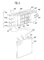
- FIG. 6 schematically represents a display module (elementary screen) connected to an excitation module.
- the display module 34 is constituted by a structure of square or rectangular shape for example and supporting the ends 32 of the optical fibers 10. These ends 32 can be arranged in lines or arranged in a determined pattern, square or hexagonal for example. A structure can for example support 100,000 ends 32 of optical fibers spaced from each other by 3 mm.
- optical fibers are therefore assembled in flat cables 40 which provide the connection with the excitation module 36.
- the optical fibers 10 are connected to sets of sections of fluorescent fibers FM1, FM2, FM3 in an identical manner to that described above; the assemblies are substantially contiguous and arranged in a row 42.
- This row 42 is sandwiched between two identical liquid crystal flat screens 44 and 46.
- the screen 46 is shown in cut away: it can be seen that it comprises a first insulating and transparent support 48, made of glass for example, supporting a transparent electrode 50, the dimensions of which determine the active surface of the screen.
- the liquid crystal 56 is held between the electrodes 54 and 50.
- An elementary cell of the liquid crystal screen is therefore formed in the interval between a segmented electrode 54 and the single electrode 50. It therefore has a strip shape.
- the control circuit 38 (not shown in this figure) is connected to the various electrodes 50 and 54. It delivers suitable control and addressing voltages and making it possible to control the state of transparency of the elementary cells.
- Each is positioned opposite a section of fluorescent fiber and forms a screen with adjustable transparency specific to a section, the width and the length of the cell being at least equal to those of the section, the degree of excitation of which is thus controlled. by the transparency of this screen.
- the excitation light sources coupled to the different sections are therefore composed of the cells of one of the liquid crystal screens illuminated by a main light source: either ambient light 60, or an artificial light source 58.
- the liquid crystal screen 44 is interposed between the row 42 of the sets of fluorescent sections and the artificial light source 58 which delivers a light capable of exciting the fluorescence of the sections.
- the liquid crystal screen 46 covers the row 42 of the sets of sections of fluorescent fibers so as to mask the ambient light 60.
- the artificial light source 58 is put out of service and the sections are excited by the ambient light modulated by the liquid crystal screen 46 controlled by the control circuit 38.
- FIG. 7 schematically represents an alternative embodiment of an excitation module.
- the latter here has a cylindrical shape: the sets of fluorescent fiber sections are arranged side by side so as to form a cylinder bordered therein by a first flat liquid crystal screen 44 itself forming a coaxial cylinder and the cells of which elementary have a strip shape capable of masking a section.
- the cylinder 62 is bordered on the outside by a second flat liquid crystal screen 46, similar to the first, itself forming a coaxial cylinder.
- the artificial light source 58 is arranged in the center of the cylinders; it emits uniformly intense light over the entire cylinder 62. This light is modulated by the liquid crystal screen 44.
- the artificial light source 58 When the ambient light 60 is sufficient to excite the fluorescence of the fluorescent fiber sections, the artificial light source 58 is put out of service. Ambient light 60 is then modulated by the liquid crystal screen 46.
Landscapes
- Physics & Mathematics (AREA)
- General Physics & Mathematics (AREA)
- Optics & Photonics (AREA)
- Nonlinear Science (AREA)
- Mathematical Physics (AREA)
- Chemical & Material Sciences (AREA)
- Crystallography & Structural Chemistry (AREA)
- Engineering & Computer Science (AREA)
- Theoretical Computer Science (AREA)
- Optical Communication System (AREA)
- Investigating, Analyzing Materials By Fluorescence Or Luminescence (AREA)
- Light Guides In General And Applications Therefor (AREA)
Applications Claiming Priority (2)
| Application Number | Priority Date | Filing Date | Title |
|---|---|---|---|
| FR8809078 | 1988-07-05 | ||
| FR8809078A FR2634031A1 (fr) | 1988-07-05 | 1988-07-05 | Dispositif de multiplexage en longueur d'onde utilisant une fibre optique |
Publications (2)
| Publication Number | Publication Date |
|---|---|
| EP0351284A2 true EP0351284A2 (de) | 1990-01-17 |
| EP0351284A3 EP0351284A3 (de) | 1990-07-04 |
Family
ID=9368081
Family Applications (1)
| Application Number | Title | Priority Date | Filing Date |
|---|---|---|---|
| EP89401903A Withdrawn EP0351284A3 (de) | 1988-07-05 | 1989-07-03 | Wellenlängenmultiplexer mit optischer Faser und Farbanzeige als Anwendung desselben |
Country Status (2)
| Country | Link |
|---|---|
| EP (1) | EP0351284A3 (de) |
| FR (1) | FR2634031A1 (de) |
Cited By (1)
| Publication number | Priority date | Publication date | Assignee | Title |
|---|---|---|---|---|
| EP0489155A4 (en) * | 1990-06-25 | 1993-01-07 | Ho-Shang Lee | Fiber optic lamp |
Family Cites Families (10)
| Publication number | Priority date | Publication date | Assignee | Title |
|---|---|---|---|---|
| US3909823A (en) * | 1974-03-26 | 1975-09-30 | Keith L Knowlton | An optical fiber variable display system utilizing a single light source |
| DE2542590A1 (de) * | 1975-09-24 | 1977-04-07 | Siemens Ag | Anzeigevorrichtung |
| US4229783A (en) * | 1979-03-12 | 1980-10-21 | Timex Corporation | Backlight for electrooptic display |
| US4371897A (en) * | 1980-09-02 | 1983-02-01 | Xerox Corporation | Fluorescent activated, spatially quantitative light detector |
| DE3247659A1 (de) * | 1982-12-23 | 1984-06-28 | Wolfgang Dr. 7000 Stuttgart Ruhrmann | Optischer sensor |
| US4618211A (en) * | 1984-03-12 | 1986-10-21 | At&T Bell Laboratories | Optical fiber tap with activatable chemical species |
| FR2573230B3 (fr) * | 1984-11-13 | 1990-02-09 | Garnier Francis | Capteur emetteur afficheur opto-electronique a ecran plat ainsi que les fibres optiques pour leur mise en oeuvre |
| FR2574564B1 (fr) * | 1984-12-10 | 1988-02-05 | Commissariat Energie Atomique | Procede d'exploitation d'un rayonnement lumineux a l'aide de fibres optiques fluorescentes, et dispositifs et appareils fonctionnels utilisant ce procede |
| FR2579808B1 (fr) * | 1985-03-29 | 1987-06-26 | Rioual Patrick | Dispositif d'affichage en couleurs a fibres optiques et cristaux liquides |
| DE3619778C1 (de) * | 1986-06-12 | 1988-01-07 | Messerschmitt Boelkow Blohm | Lichtleitfaser fuer ein Datenbussystem |
-
1988
- 1988-07-05 FR FR8809078A patent/FR2634031A1/fr active Pending
-
1989
- 1989-07-03 EP EP89401903A patent/EP0351284A3/de not_active Withdrawn
Cited By (1)
| Publication number | Priority date | Publication date | Assignee | Title |
|---|---|---|---|---|
| EP0489155A4 (en) * | 1990-06-25 | 1993-01-07 | Ho-Shang Lee | Fiber optic lamp |
Also Published As
| Publication number | Publication date |
|---|---|
| EP0351284A3 (de) | 1990-07-04 |
| FR2634031A1 (fr) | 1990-01-12 |
Similar Documents
| Publication | Publication Date | Title |
|---|---|---|
| EP0567385B1 (de) | Objektbilderfassungsvorrichtung | |
| EP1110029B1 (de) | Leuchtende anzeigetafel | |
| WO1995025460A1 (fr) | Dispositif d'imagerie endoscopique ou fibroscopique en fluorescence dans l'infrarouge | |
| EP3207541B1 (de) | In den bildschirm einer elektronischen anzeigevorrichtung integriertes polarisierendes fotovoltaikmodul | |
| EP1794631A1 (de) | Beleuchteter leuchtkasten mit leuchtdioden | |
| EP0762182B1 (de) | Hintergrundbeleuchtungssystem für elektrooptischen Modulator und Anzeigevorrichtung mit einem solchen Beleuchtungssystem | |
| FR2722305A1 (fr) | Dispositif d'eclairage d'afficheur a cristaux liquides et son procede de fabrication | |
| FR3020473A1 (fr) | Dispositif d'affichage a cellules photovoltaiques integrees avec luminosite et reflectivite ameliorees | |
| FR2655430A1 (fr) | Coupeur optique et systeme informatique a processeurs repartis. | |
| EP0187561A1 (de) | Verfahren zur Nutzung einer Lichtstrahlung mittels fluoreszierender optischer Fasern und Vorrichtungen oder Geräte die dieses Verfahren anwenden | |
| EP0351284A2 (de) | Wellenlängenmultiplexer mit optischer Faser und Farbanzeige als Anwendung desselben | |
| FR2691579A1 (fr) | Système de conversion d'une image infrarouge en image visible ou proche infrarouge. | |
| EP0937273B1 (de) | Kompakte vorrichtung für beleuchtung | |
| FR2737799A1 (fr) | Perfectionnement au dispositif d'affichage comportant un systeme d'eclairage arriere fournissant une lumiere collimatee | |
| FR2609778A1 (fr) | Source de lumiere froide a forte luminance et utilisation pour un dispositif de visualisation d'images | |
| EP0827640B1 (de) | Verfahren und laservorrichtung zur optischen nachrichten-übertragung | |
| BE1016311A3 (fr) | Dispositif d'illumination d'une jante d'un vehicule. | |
| FR3097935A1 (fr) | Dispositif d’éclairage et/ou de signalisation | |
| WO2004055566A1 (fr) | Syteme optique base sur fibres optiques a reseau incline | |
| FR2619937A1 (fr) | Modulateur optique a deux dimensions | |
| FR2566139A1 (fr) | Dispositif de distribution d'energie lumineuse et son utilisation a la commutation optique | |
| FR2858705A1 (fr) | Panneau lumineux et application aux ecrans de visualisation du type video | |
| EP0524878A1 (de) | Halbleitender Mikrowellenabsorber mit optischer Steuerung | |
| WO2006013163A1 (fr) | Source d'eclairage pour afficheur a cristaux liquides | |
| FR2774476A1 (fr) | Procede pour l'etablissement de plusieurs circuits de donnees sur une fibre optique et dispositif pour la mise en oeuvre du procede. |
Legal Events
| Date | Code | Title | Description |
|---|---|---|---|
| PUAI | Public reference made under article 153(3) epc to a published international application that has entered the european phase |
Free format text: ORIGINAL CODE: 0009012 |
|
| AK | Designated contracting states |
Kind code of ref document: A2 Designated state(s): DE FR GB IT SE |
|
| PUAL | Search report despatched |
Free format text: ORIGINAL CODE: 0009013 |
|
| RHK1 | Main classification (correction) |
Ipc: G09F 9/30 |
|
| AK | Designated contracting states |
Kind code of ref document: A3 Designated state(s): DE FR GB IT SE |
|
| 17P | Request for examination filed |
Effective date: 19901208 |
|
| STAA | Information on the status of an ep patent application or granted ep patent |
Free format text: STATUS: THE APPLICATION IS DEEMED TO BE WITHDRAWN |
|
| 18D | Application deemed to be withdrawn |
Effective date: 19930201 |