EP0351257B1 - Apparatus for the optical profile control of a tube or bore - Google Patents
Apparatus for the optical profile control of a tube or bore Download PDFInfo
- Publication number
- EP0351257B1 EP0351257B1 EP89401310A EP89401310A EP0351257B1 EP 0351257 B1 EP0351257 B1 EP 0351257B1 EP 89401310 A EP89401310 A EP 89401310A EP 89401310 A EP89401310 A EP 89401310A EP 0351257 B1 EP0351257 B1 EP 0351257B1
- Authority
- EP
- European Patent Office
- Prior art keywords
- tube
- cavity
- wall
- bore
- internal profile
- Prior art date
- Legal status (The legal status is an assumption and is not a legal conclusion. Google has not performed a legal analysis and makes no representation as to the accuracy of the status listed.)
- Expired - Lifetime
Links
Images


Classifications
-
- G—PHYSICS
- G01—MEASURING; TESTING
- G01B—MEASURING LENGTH, THICKNESS OR SIMILAR LINEAR DIMENSIONS; MEASURING ANGLES; MEASURING AREAS; MEASURING IRREGULARITIES OF SURFACES OR CONTOURS
- G01B11/00—Measuring arrangements characterised by the use of optical techniques
- G01B11/24—Measuring arrangements characterised by the use of optical techniques for measuring contours or curvatures
-
- G—PHYSICS
- G01—MEASURING; TESTING
- G01B—MEASURING LENGTH, THICKNESS OR SIMILAR LINEAR DIMENSIONS; MEASURING ANGLES; MEASURING AREAS; MEASURING IRREGULARITIES OF SURFACES OR CONTOURS
- G01B11/00—Measuring arrangements characterised by the use of optical techniques
- G01B11/08—Measuring arrangements characterised by the use of optical techniques for measuring diameters
- G01B11/12—Measuring arrangements characterised by the use of optical techniques for measuring diameters internal diameters
-
- G—PHYSICS
- G01—MEASURING; TESTING
- G01B—MEASURING LENGTH, THICKNESS OR SIMILAR LINEAR DIMENSIONS; MEASURING ANGLES; MEASURING AREAS; MEASURING IRREGULARITIES OF SURFACES OR CONTOURS
- G01B11/00—Measuring arrangements characterised by the use of optical techniques
- G01B11/30—Measuring arrangements characterised by the use of optical techniques for measuring roughness or irregularity of surfaces
- G01B11/303—Measuring arrangements characterised by the use of optical techniques for measuring roughness or irregularity of surfaces using photoelectric detection means
Definitions
- the present invention relates to an apparatus for the optical control of the internal profile of a tube or a bore.
- This invention finds its field of application mainly in the in situ inspection of the tubes of the steam generators of the nuclear power stations but can relate to the inspection of tubes or bores of great lengths and of small diameters which can possibly include elbows.
- the tubes of the steam generators must be inspected for defects making them susceptible to cracking under stress.
- a known technique for determining the internal profile of a tube, uses a probe with several fingers to simultaneously measure the internal radii of the tube, at several locations around its circumference, when the probe is pulled into the tube, by detection of the deflection. strain gauges mounted on the fingers. Such a device is described for example in French patent 2,553,877.
- the object of the present invention is to remedy these drawbacks by proposing, for controlling the internal profile of a cavity of revolution, an optical device whose various mechanical and opto-electronic components allow significant miniaturization.
- the apparatus according to the invention is of the type comprising a probe capable of being displaced in translation inside the cavity and connected to a supply and analysis system placed outside the cavity.
- this device comprises a coherent light source placed inside the probe and it is characterized in that the light source is associated with a convergence optical system and with a mirror to illuminate the wall of the cavity along a line corresponding to the intersection of the wall with a cross section, an image of this line being formed from the light re-emitted by the wall, on an opto-electronic sensor also placed in the probe and the deviations of this image compared to a theoretical image representing the variations of the internal profile of the cavity.
- the coherent source can illuminate the wall of the cavity, either by scanning it by means of a rotating mirror, or permanently by means of a conical mirror.
- the wall is illuminated by scanning by means of a rotating mirror
- the light re-emitted by the wall of the cavity can advantageously be returned to the opto-electronic sensor by means of a second synchronous rotating mirror of the first.
- the opto-electronic sensor can be linear if it rotates in synchronism with the rotating mirrors.
- the re-emitted light can be returned, by means of a wide angle optical objective, to the opto-electronic sensor.
- the light re-emitted by the wall of the cavity can be returned to the opto-electronic sensor by means of a conical mirror.
- FIG. 1 shows the operating principle of a probe according to a first embodiment.
- FIG. 2 represents the operating principle of a probe according to a second embodiment.
- FIG. 3 represents the operating principle of a probe according to a third embodiment.
- FIG. 4 represents a probe according to the invention, produced in two parts.
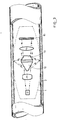
- FIG. 5 represents another probe according to the invention, produced in a single part.
- FIG. 1 which represents the operating principle of a first embodiment of the invention, there can be seen a probe 1, shown in dotted lines, which moves in a tube 2.
- the illumination of the internal surface of the tube 2 is advantageously obtained by a longitudinal laser beam 3, coming from a source and reflecting on two prisms 5 and 6 which refocuses it on a reflecting mirror 7 on the internal surface of the tube 2
- This mirror 7 is rotated about the longitudinal axis of the probe 1 by a motorization 8 so that the laser beam scans the internal surface of the tube 2 along a line corresponding to the intersection with a cross section.
- the internal surface of the tube 2 thus lit behaves as an emissive object, the image of which is formed, by means of a wide-angle objective 9 in an observation plane in which there is a matrix opto-electronic sensor 10.
- This image on the sensor 10 consists of a line which corresponds to the internal profile of the tube 2.
- the typical profile corresponds to a theoretical line and any variation in the profile results in a deviation of the image from this theoretical line.
- An analysis of the image obtained on the opto-electronic sensor 10 therefore makes it possible to know the internal profile of the tube 2.
- the sensitivity of the device will therefore depend on the resolving power of the opto-electronic sensor 10. If there are N measurement points distributed over a diameter of the image plane, the resolution on the measurement of the diameter D of the tube will be equal to: D NOT
- the coherent light beam from the laser source 4 is transformed, by means of an optical system 11 into a relatively wide beam.
- This beam illuminates a conical reflector 12, the axis of which merges with the longitudinal axis of the probe 1.
- the optical system 11 is determined in such a way that the light beam converges on the internal surface of the tube 2.
- the latter is thus lit along a line which corresponds to its intersection with a cross section of the tube.
- an image of this line is formed, by means of a wide-angle objective 9 on a matrix opto-electronic sensor 10.
- the mode of illumination of the internal wall of the tube 2 is identical to that of the embodiment of FIG. 2.
- the return of the re-emitted light is done by means of a second conical mirror 13.
- the image is then formed on the opto-electronic sensor 10 by means of an optic 14.
- the conical return mirror 13 advantageously has a non-linear section variation so as to create a non-linear enlargement making it possible to improve the resolution of the measurement, only the periphery of the image plane delivering relevant information. This non-linear enlargement ratio thus makes it possible to improve the accuracy of the measurement for a given two-dimensional observation system.
- the probe 1 is broken down into two warheads 1A and 1B.
- the first warhead 1A comprises, by way of example, the whole of the device represented in FIG. 3, with the exception of the opto-electronic sensor 10.
- the latter and the hybrid operating circuit 15 which itself is associated are placed in the second warhead 1B.
- the connection between the warheads 1A and 1B is done by means of an optical fiber 16. This optical fiber receives on its input 17 the image formed by the optics 14.
- This image available at the output 18 of the optical fiber is transposed, by means of a lens 19 on the opto-electronic sensor 10.
- the signal produced by the hybrid circuit 15 is transmitted to the outside for analysis by a cable 20.
- the sensor 10 could be in direct contact with the end 18 of the fiber, thus making the objective 19 useless.
- the solution which has just been presented makes it possible to have a relatively large volume for the part electronic, but it requires an optical fiber 16 of sufficient resolution, flexibility and robustness. A variant would therefore consist in leaving the opto-electronic sensor 10 in the warhead 1A, in placing the processing electronics in the warhead 1B with a short wire connection between the two warheads. If this solution has the advantage of providing an even greater volume for the electronic part, it requires special attention to the quality of the high frequency links.
- Figure 6 along a section VI-VI of Figure 5 allows to understand how the light beam can explore almost all of the inner wall of the tube. Windows which occupy almost the entire periphery of the probe are formed in the wall of the latter. The end parts of the probe are connected to each other only by arms 22 of minimum thickness to ensure the mechanical rigidity of the assembly. One can thus imagine that the two ends of the probe are joined together by a transparent ring having the required optical qualities.
Description
La présente invention concerne un appareil pour le contrôle optique du profil interne d'un tube ou d'un alésage.The present invention relates to an apparatus for the optical control of the internal profile of a tube or a bore.
Cette invention trouve son domaine d'application principalement dans l'inspection in situ des tubes des générateurs de vapeur des centrales nucléaires mais peut se rapporter à l'inspection de tubes ou alésages de grandes longueurs et de faibles diamètres pouvant comporter éventuellement des coudes.This invention finds its field of application mainly in the in situ inspection of the tubes of the steam generators of the nuclear power stations but can relate to the inspection of tubes or bores of great lengths and of small diameters which can possibly include elbows.
Les tubes des générateurs de vapeur doivent être inspectés pour déceler les défauts les rendant susceptibles de fissurations sous contrainte.The tubes of the steam generators must be inspected for defects making them susceptible to cracking under stress.
Cette inspection se fait soit à partir de la technique mettant en oeuvre les courants de Foucault pour la détection de défauts dans la paroi des tubes. Une telle méthode est décrite dans le brevet français 2.320.542. Elle se fait aussi par la mesure du profil interne du tube, la présente invention entre dans cette dernière catégorie.This inspection is done either from the technique using eddy currents for the detection of faults in the wall of the tubes. Such a method is described in French patent 2,320,542. It is also done by measuring the internal profile of the tube, the present invention falls into this latter category.
Une technique connue, de détermination du profil interne d'un tube, utilise une sonde à plusieurs doigts pour mesurer simultanément les rayons internes du tube, à plusieurs emplacements autour de sa circonférence, lorsque la sonde est tirée dans le tube, par détection du fléchissement de jauges de contrainte montées sur les doigts. Un tel dispositif est décrit par exemple dans le brevet français 2.553.877.A known technique, for determining the internal profile of a tube, uses a probe with several fingers to simultaneously measure the internal radii of the tube, at several locations around its circumference, when the probe is pulled into the tube, by detection of the deflection. strain gauges mounted on the fingers. Such a device is described for example in French patent 2,553,877.
Une autre technique connue, décrite par exemple dans le brevet français 2.513.753 utilise une sonde profilométrique ayant une tête rotative entraînée par un moteur tournant autour d'un axe longitudinal de la sonde. L'organe de mesure porté par la tête est en contact avec la surface de la paroi interne.Another known technique, described for example in French patent 2,513,753 uses a probe profilometric having a rotary head driven by a motor rotating around a longitudinal axis of the probe. The measuring device carried by the head is in contact with the surface of the internal wall.
Ces dispositifs connus sont limités dans leur domaine d'utilisation par le contact nécessaire entre l'organe de mesure et la paroi interne, ainsi que par les dispositifs mécaniques associés rendant leur miniaturisation difficile voir impossible pour pouvoir être mis en application dans les zones cintrées des tubes des générateurs de vapeur.These known devices are limited in their field of use by the necessary contact between the measuring member and the internal wall, as well as by the associated mechanical devices making their miniaturization difficult if not impossible to be able to be applied in the curved areas of the steam generator tubes.
Une autre technique connue, notamment par les brevets français 2.065.549 et 2.195337 et par le brevet britannique 2.047882, consiste à effectuer un contrôle optique. A cet effet, la paroi interne de la cavité est illuminée suivant une section droite déplaçable en translation et la lumière réémise est captée sur un dispositif photo-sensible qui permet d'en faire une analyse. La source et le récepteur étant à l'extérieur de la cavité, ces dispositifs sont réservés aux cavités rectilignes de faibles profondeurs.Another known technique, notably by French patents 2,065,549 and 2,195,337 and by British patent 2,047,882, consists in carrying out an optical control. To this end, the internal wall of the cavity is illuminated in a cross section movable in translation and the re-emitted light is captured on a photo-sensitive device which makes it possible to analyze it. The source and the receiver being outside the cavity, these devices are reserved for rectilinear cavities of shallow depths.
Pour étudier les cavités de plus grandes profondeurs, il a déja été proposé par le US-A-4.199.258, de placer une source de lumière à l'intérieur de la sonde. Mais ce dispositif ne permet d'éclairer que quelques points de la circonférence, quatre de préférence, il ne permet donc pas, par des déplacements de la sonde, de contrôler la totalité de la surface de la cavité, mais tout au plus des variations de diamètre.To study cavities of greater depths, it has already been proposed by US-A-4,199,258, to place a light source inside the probe. But this device allows only a few points of the circumference to be illuminated, preferably four, it therefore does not allow, by displacements of the probe, to control the entire surface of the cavity, but at most variations in diameter.
La présente invention a pour objet de remédier à ces inconvénients en proposant, pour le contrôle du profil interne d'une cavité de révolution, un dispositif optique dont les différents composants mécaniques et opto-électroniques permettent une miniaturisation importante.The object of the present invention is to remedy these drawbacks by proposing, for controlling the internal profile of a cavity of revolution, an optical device whose various mechanical and opto-electronic components allow significant miniaturization.
L'appareil selon l'invention est du genre comportant une sonde capable d'être déplacée en translation à l'intérieur de la cavité et reliée à un système d'alimentation et d'analyse placé à l'extérieur de la cavité. Conformément à l'invention cet appareil comporte une source de lumière cohérente placée à l'intérieur de la sonde et il se caractérise en ce que la source de lumière est associée à un système optique de convergence et à un miroir pour illuminer la paroi de la cavité suivant une ligne correspondant à l'intersection de la paroi avec une section droite, une image de cette ligne étant formée à partir de la lumière réémise par la paroi, sur un capteur opto électronique également placé dans la sonde et les écarts de cette image par rapport à une image théorique représentant les variations du profil interne de la cavité.The apparatus according to the invention is of the type comprising a probe capable of being displaced in translation inside the cavity and connected to a supply and analysis system placed outside the cavity. According to the invention, this device comprises a coherent light source placed inside the probe and it is characterized in that the light source is associated with a convergence optical system and with a mirror to illuminate the wall of the cavity along a line corresponding to the intersection of the wall with a cross section, an image of this line being formed from the light re-emitted by the wall, on an opto-electronic sensor also placed in the probe and the deviations of this image compared to a theoretical image representing the variations of the internal profile of the cavity.
Suivant différents modes de réalisation, la source cohérente peut illuminer la paroi de la cavité, soit en la balayant au moyen d'un miroir tournant, soit de manière permanente au moyen d'un miroir conique.
Lorsque la paroi est illuminée par balayage au moyen d'un miroir tournant, la lumière réémise par la paroi de la cavité peut avantageusement être renvoyée, sur le capteur opto-électronique au moyen d'un second miroir tournant synchrone du premier. Dans ce cas, le capteur opto-électronique peut être linéaire si il tourne en synchronisme avec les miroirs tournants.According to different embodiments, the coherent source can illuminate the wall of the cavity, either by scanning it by means of a rotating mirror, or permanently by means of a conical mirror.
When the wall is illuminated by scanning by means of a rotating mirror, the light re-emitted by the wall of the cavity can advantageously be returned to the opto-electronic sensor by means of a second synchronous rotating mirror of the first. In this case, the opto-electronic sensor can be linear if it rotates in synchronism with the rotating mirrors.
Dans un autre mode de réalisation, et quel que soit le mode d'illumination de la paroi, la lumière réémise peut être renvoyée, au moyen d'un objectif optique grand angle, sur le capteur opto-électronique.In another embodiment, and whatever the mode of illumination of the wall, the re-emitted light can be returned, by means of a wide angle optical objective, to the opto-electronic sensor.
Enfin dans un dernier mode de réalisation possible, la lumière réémise par la paroi de la cavité peut être renvoyée sur le capteur opto-électronique au moyen d'un miroir conique.Finally, in a last possible embodiment, the light re-emitted by the wall of the cavity can be returned to the opto-electronic sensor by means of a conical mirror.
En se référant aux figures schématiques jointes, données à titre non limitatif, on va décrire quelques exemples de mise en oeuvre de l'invention.Referring to the attached schematic figures, given without limitation, we will describe some examples of implementation of the invention.
La figure 1 représente le principe de fonctionnement d'une sonde suivant un premier mode de réalisation.FIG. 1 shows the operating principle of a probe according to a first embodiment.
La figure 2 représente le principe de fonctionnement d'une sonde suivant un deuxième mode de réalisation.FIG. 2 represents the operating principle of a probe according to a second embodiment.
La figure 3 représente le principe de fonctionnement d'une sonde suivant un troisième mode de réalisation.FIG. 3 represents the operating principle of a probe according to a third embodiment.
La figure 4 représente une sonde conforme à l'invention, réalisée en deux parties.FIG. 4 represents a probe according to the invention, produced in two parts.
La figure 5 représente une autre sonde conforme à l'invention, réalisée en une seule partie.
Sur la figure 1 qui représente le principe de fonctionnement d'un premier mode de réalisation de l'invention, on voit une sonde 1, représentée en pointillés, qui se déplace dans un tube 2.FIG. 5 represents another probe according to the invention, produced in a single part.
In FIG. 1 which represents the operating principle of a first embodiment of the invention, there can be seen a
L'éclairage de la surface interne du tube 2 est obtenu avantageusement par un faisceau laser longitudinal 3, issu d'une source et se réfléchissant sur deux prismes 5 et 6 qui le recentre sur un miroir 7 de renvoi sur la surface interne du tube 2. Ce miroir 7 est entraîné en rotation, autour de l'axe longitudinal de la sonde 1 par une motorisation 8 afin que le faisceau laser balaie la surface interne du tube 2 suivant une ligne correspondant à l'intersection avec une section droite.The illumination of the internal surface of the
La surface interne du tube 2 ainsi éclairée se comporte en objet émissif dont l'image se forme, par l'intermédiaire d'un objectif grand angle 9 dans un plan d'observation dans lequel se trouve un capteur opto-électronique matriciel 10. Cette image sur le capteur 10 est constituée d'une ligne qui correspond au profil interne du tube 2. Au profil type correspond une ligne théorique et toute variation du profil se traduit par un écart de l'image par rapport à cette ligne théorique. Une analyse de l'image obtenue sur le capteur opto-électronique 10 permet donc de connaître le profil interne du tube 2. La sensibilité du dispositif dépendra donc du pouvoir de résolution du capteur opto-électronique 10. Si l'on dispose de N points de mesure répartis sur un diamètre du plan image, la résolution sur la mesure du diamètre D du tube sera égale à :![]()
![]()
La paroi interne étant balayée grâce au miroir tournant 7, on peut imaginer que l'analyse de la lumière réémise soit faite au moyen d'un second miroir tournant, synchrone du premier et réalisant, sur le capteur opto-électronique l'image de la ligne éclairée sous forme d'un point. Dans cette hypothèse le capteur opto-électronique pourrait être linéaire, à condition qu'il soit tournant et synchrone des miroirs.
La complication mécanique entraînée trouverait sa compensation dans une amélioration du pouvoir de résolution, celui-ci étant meilleur pour un capteur opto-électronique linéaire que pour un capteur opto-électronique matriciel.The internal wall being scanned thanks to the rotating mirror 7, one can imagine that the analysis of the re-emitted light is made by means of a second rotating mirror, synchronous with the first and realizing, on the opto-electronic sensor the image of the line lit as a point. In this hypothesis, the optoelectronic sensor could be linear, provided that it is rotating and synchronous with the mirrors.
The mechanical complication involved would find its compensation in an improvement of the resolution power, this being better for a linear opto-electronic sensor than for a matrix opto-electronic sensor.
Dans la variante représentée par la figure 2, le faisceau de lumière cohérente issu de la source laser 4 est transformé, au moyen d'un système optique 11 en un faisceau relativement large. Ce faisceau éclaire un réflecteur conique 12 dont l'axe se confond avec l'axe longitudinal de la sonde 1. Le système optique 11 est déterminé de telle manière que le faisceau de lumière converge sur la surface interne du tube 2. Celle-ci est ainsi éclairée suivant une ligne qui correspond à son intersection avec une section droite du tube. Comme précédemment, une image de cette ligne est formée, par l'intermédiaire d'un objectif grand angle 9 sur un capteur opto-électronique matriciel 10.In the variant shown in Figure 2, the coherent light beam from the
Dans la variante représentée par la figure 3, le mode d'illumination de la paroi interne du tube 2 est identique à celui de la réalisation de la figure 2. Par contre, le renvoi de la lumière réémise se fait au moyen d'un second miroir conique 13. L'image étant ensuite formée sur le capteur opto-électronique 10 au moyen d'une optique 14. Le miroir conique 13 de renvoi a avantageusement une variation de section non linéaire de manière à créer un agrandissement non linéaire permettant d'améliorer la résolution de la mesure, seule la périphérie du plan image délivrant des informations pertinentes. Ce rapport d'agrandissement non linéaire permet ainsi d'améliorer la précision de la mesure pour un système d'observation bidimensionnel donné.
Les impératifs de diamètre disponible à l'intérieur des tubes des échangeurs de chaleur des générateurs de vapeur conduisent à proposer plusieurs solutions permettant la miniaturisation de la sonde.
Dans la disposition représentée à la figure 4, la sonde 1 est décomposée en deux ogives 1A et 1B. La première ogive 1A comprend, à titre d'exemple, l'ensemble du dispositif représenté à la figure 3, à l'exception du capteur opto-électronique 10. En effet, celui-ci et le circuit hybride d'exploitation 15 qui lui est associé sont placés dans la seconde ogive 1B. La liaison entre les ogives 1A et 1B se fait au moyen d'une fibre optique 16. Cette fibre optique recoit sur son entrée 17 l'image formée par l'optique 14.In the variant represented by FIG. 3, the mode of illumination of the internal wall of the
The imperatives of diameter available inside the tubes of the heat exchangers of the steam generators lead to proposing several solutions allowing the miniaturization of the probe.
In the arrangement shown in Figure 4, the
Cette image disponible à la sortie 18 de la fibre optique est transposée, au moyen d'un objectif 19 sur le capteur opto-électronique 10. Le signal produit par le circuit hybride 15 est transmis à l'extérieur pour analyse par un cable 20. Dans une autre forme, le capteur 10 pourrait être en contact direct avec l'extrémité 18 de la fibre, rendant ainsi inutile l'objectif 19.
La solution qui vient d'être présentée permet de disposer d'un volume relativement important pour la partie électronique, mais elle nécessite une fibre optique 16 de résolution, de souplesse et de robustesse suffisantes. Une variante consisterait donc à laisser le capteur opto-électronique 10 dans l'ogive 1A, à placer l'électronique de traitement dans l'ogive 1B avec une liaison filaire de courte longueur entre les deux ogives. Si cette solution possède l'avantage de procurer un volume encore plus important pour la partie électronique, elle nécessite une attention particulière sur la qualité des liaisons à fréquences élevées.This image available at the
The solution which has just been presented makes it possible to have a relatively large volume for the part electronic, but it requires an
Enfin, une dernière variante, représentée à la figure 5, est proposée. Elle consiste à intégrer à l'ogive unique de la sonde 1 toute la partie optique et opto-électronique ainsi qu'une partie minimale 21 du circuit électronique, le reste de celui-ci se trouvant à l'extérieur.Finally, a last variant, shown in Figure 5, is proposed. It consists in integrating into the single warhead of the
La figure 6, suivant une coupe VI-VI de la figure 5 permet de comprendre comment le faisceau lumineux peut explorer la quasi totalité de la paroi interne du tube. Des fenêtres qui occupent la presque totalité de la périphérie de la sonde sont ménagées dans la paroi de celle-ci.
Les parties extrêmes de la sonde ne sont reliées entre-elles que par des bras 22 d'épaisseur minimale pour assurer la rigidité mécanique de l'ensemble.
On peut ainsi imaginer que les deux extrémités de la sonde soient réunies entre elles par une bague transparente ayant les qualités optiques requises.Figure 6, along a section VI-VI of Figure 5 allows to understand how the light beam can explore almost all of the inner wall of the tube. Windows which occupy almost the entire periphery of the probe are formed in the wall of the latter.
The end parts of the probe are connected to each other only by
One can thus imagine that the two ends of the probe are joined together by a transparent ring having the required optical qualities.
Claims (7)
- Apparatus for optically monitoring the internal profile of a tube or of a bore, of the type including a probe (1) capable of being moved translationally inside the cavity (2) of the tube or of the bore and connected to a supply and analysis system placed outside the cavity, a light source (4) being placed inside the said probe, characterised in that the light source is combined with an optical convergence system and with a mirror for illuminating the wall of the cavity along a line corresponding to the intersection of the wall with a cross-section and in that an image of this line is formed, from the light re-emitted by the wall, on an optoelectronic sensor (10) also placed in the probe and the deviations of this image with respect to a theoretical image represent the variations in the internal profile of the cavity.
- Apparatus for optically monitoring the internal profile of a tube or of a bore, according to Claim 1, characterised in that the light source (4) emits a fine beam which is projected onto the wall of the cavity by means of a mirror (7) rotating about the longitudinal axis of the probe, the said mirror (7) being driven by a motor (8).
- Apparatus for optically monitoring the internal profile of a tube or of a bore, according to Claim 1, characterised in that the light source (4) emits a beam which is reflected by a conical mirror (12) so as to illuminate continuously the entire line corresponding to the intersection of the wall with the cross-section of the cavity.
- Apparatus for optically monitoring the internal profile of a tube or of a bore, according to Claim 2, characterised in that the light re-emitted by the wall of the cavity is sent back to the optoelectronic sensor (10) by means of a mirror rotating synchronously with the first.
- Apparatus for optically monitoring the internal profile of a tube or of a bore, according to one of Claims 2 and 3, characterised in that the light re-emitted by the wall of the cavity is sent back to the optoelectronic sensor (10) by means of a wide-angle optical objective (9).
- Apparatus for optically monitoring the internal profile of a tube or of a bore, according to Claim 3, characterised in that the light re-emitted by the wall of the cavity is sent back to the optoelectronic sensor (10) by means of a conical mirror (13).
- Apparatus for optically monitoring the internal profile of a tube or of a bore, according to Claim 6, characterised in that the conical mirror (13) for reflecting the re-emitted light has a non-linear cross-section variation.
Applications Claiming Priority (2)
| Application Number | Priority Date | Filing Date | Title |
|---|---|---|---|
| FR8806588 | 1988-05-17 | ||
| FR8806588A FR2631697B1 (en) | 1988-05-17 | 1988-05-17 | APPARATUS FOR OPTICAL CONTROL OF THE INTERNAL PROFILE OF A TUBE OR BORE |
Publications (2)
| Publication Number | Publication Date |
|---|---|
| EP0351257A1 EP0351257A1 (en) | 1990-01-17 |
| EP0351257B1 true EP0351257B1 (en) | 1993-01-20 |
Family
ID=9366363
Family Applications (1)
| Application Number | Title | Priority Date | Filing Date |
|---|---|---|---|
| EP89401310A Expired - Lifetime EP0351257B1 (en) | 1988-05-17 | 1989-05-11 | Apparatus for the optical profile control of a tube or bore |
Country Status (5)
| Country | Link |
|---|---|
| US (1) | US4967092A (en) |
| EP (1) | EP0351257B1 (en) |
| JP (1) | JP2593938B2 (en) |
| DE (1) | DE68904489T2 (en) |
| FR (1) | FR2631697B1 (en) |
Families Citing this family (70)
| Publication number | Priority date | Publication date | Assignee | Title |
|---|---|---|---|---|
| GB8914960D0 (en) * | 1989-06-29 | 1989-08-23 | Cencit Europ | Inspection apparatus for tubular members |
| US5265129A (en) * | 1992-04-08 | 1993-11-23 | R. Brooks Associates, Inc. | Support plate inspection device |
| US5305356B1 (en) * | 1992-05-14 | 1998-09-01 | Brooks Support Systems Inc | Inspection device |
| US5449919A (en) * | 1994-02-08 | 1995-09-12 | The Carsen Group Inc. | Borescope drill pipe and light guide sleeve |
| CA2145232A1 (en) * | 1994-03-24 | 1995-09-25 | Arie Avny | Viewing method and apparatus particularly useful for viewing the interior of the large intestine |
| US5576826A (en) * | 1995-05-03 | 1996-11-19 | Hamar Laser Instruments, Inc. | Alignment laser with over-flooded aperture system and dual-mode self-centering target |
| US5654795A (en) * | 1995-06-06 | 1997-08-05 | Crc-Evans Pipeline International, Inc. | Internal visual weld inspection apparatus |
| US5903306A (en) * | 1995-08-16 | 1999-05-11 | Westinghouse Savannah River Company | Constrained space camera assembly |
| US5933231A (en) * | 1996-07-10 | 1999-08-03 | Industrial Technology Institute | Method and system for measuring cavities and probe for use therein |
| US5822057A (en) * | 1996-07-26 | 1998-10-13 | Stress Engineering Services, Inc. | System and method for inspecting a cast structure |
| DE19714202A1 (en) * | 1997-04-07 | 1998-10-15 | Bosch Gmbh Robert | Device for the optical inspection of surfaces |
| US8760657B2 (en) * | 2001-04-11 | 2014-06-24 | Gas Sensing Technology Corp | In-situ detection and analysis of methane in coal bed methane formations with spectrometers |
| AU2001269717A1 (en) * | 2000-05-30 | 2001-12-11 | Oyo Corp. U.S.A. | Apparatus and method for detecting pipeline defects |
| US6661506B2 (en) | 2000-08-24 | 2003-12-09 | Og Technologies, Inc. | Engine bearing inspection system |
| IL138237A (en) | 2000-09-04 | 2008-12-29 | Stryker Gi Ltd | Double sleeve endoscope |
| US20040189987A1 (en) * | 2000-11-15 | 2004-09-30 | Quest Integrated Inc. | A method for reformer tube in situ inspection radius calculation |
| US6879404B2 (en) * | 2001-01-22 | 2005-04-12 | Balluff Gmbh | Device and method for checking bores in or edges on an object of measurement |
| DE10103177A1 (en) * | 2001-01-22 | 2002-08-01 | Balluff Gmbh | Gratprüfungs sensor device |
| EP1392155B1 (en) * | 2001-05-17 | 2012-09-05 | Oticon A/S | Method and apparatus for obtaining position data relating to a probe in the ear canal |
| US7206067B2 (en) * | 2001-05-17 | 2007-04-17 | Oticon A/S | Method and apparatus for obtaining geometrical data relating to the ear canal of the human body |
| DE10209953B4 (en) * | 2002-03-06 | 2007-03-22 | Rheinmetall Waffe Munition Gmbh | Device for measuring the wear of the inner surface of pipes |
| US6862099B2 (en) * | 2002-04-05 | 2005-03-01 | Varco I/P | Tubular ovality testing |
| US6931149B2 (en) * | 2002-04-19 | 2005-08-16 | Norsk Elektro Optikk A/S | Pipeline internal inspection device and method |
| US7312454B2 (en) * | 2003-07-16 | 2007-12-25 | The Boeing Company | Non-destructive infrared inspection device |
| US6908428B2 (en) * | 2003-09-04 | 2005-06-21 | Sightline Technologies Ltd. | Sleeve for endoscopic tools |
| WO2005067422A2 (en) * | 2003-12-25 | 2005-07-28 | Quest Trutec, Lp | Method and apparatus for inspecting reformer tube |
| DE102004006680B3 (en) * | 2004-02-09 | 2006-01-12 | Balluff Gmbh | Sensor device for testing surfaces |
| US7847947B2 (en) * | 2005-06-27 | 2010-12-07 | Colin Jeffress | Spectroscopic lance for bulk sampling |
| JP4984497B2 (en) * | 2005-11-10 | 2012-07-25 | 株式会社日立製作所 | Underwater inspection device |
| DE102005059550A1 (en) * | 2005-12-13 | 2007-06-14 | Siemens Ag | Optical measuring device for measuring inner wall of e.g. ear channel, in animal, has rotatable reflector rotatable around rotary axis so that inner wall of cavity is scanned along line circulating rotary axis |
| US8328731B2 (en) * | 2006-01-06 | 2012-12-11 | Phonak Ag | Method and system for reconstructing the three-dimensional shape of the surface of at least a portion of an ear canal and/or of a concha |
| DE102006041847B3 (en) * | 2006-09-06 | 2008-01-10 | Lars Struckmann | Optical inspection device for e.g. controlling technical process and/or for quality security of inner surface of hollow body, has camera transferring photos of inner surface section to external monitor or image processing |
| US8860954B2 (en) * | 2006-10-04 | 2014-10-14 | Schlumberger Technology Corporation | Physical property measurement device |
| US7557914B2 (en) * | 2006-10-09 | 2009-07-07 | The Boeing Company | Rotating laser measurement system |
| DE202006017076U1 (en) | 2006-11-08 | 2007-01-04 | Fraunhofer-Gesellschaft zur Förderung der angewandten Forschung e.V. | Apparatus for optical contact free inspection of a tube or pipeline using optical triangulation |
| FR2923595B1 (en) * | 2007-11-09 | 2009-12-11 | Thales Sa | OPTICAL SENSOR FOR MEASURING THE DEFORMATION DURING THE TIME OF A DEFORMABLE FLAT STRUCTURE |
| JP5309542B2 (en) * | 2007-12-05 | 2013-10-09 | 株式会社ニコン | Measuring apparatus and method |
| DE102008045746A1 (en) * | 2008-09-04 | 2010-03-25 | Lufthansa Technik Ag | Method for measuring the interior of an aircraft |
| NO333307B1 (en) * | 2008-11-24 | 2013-04-29 | Statoil Asa | Apparatus and method for optical measurement of the thickness of any deposit of material on the interior wall of a structure |
| JP2013522599A (en) * | 2010-03-09 | 2013-06-13 | フェデラル−モーグル コーポレイション | Bore inspection system and inspection method using the same |
| US8004695B1 (en) * | 2010-08-16 | 2011-08-23 | Paccar Inc. | Measurement of film thickness in motor exhaust systems |
| JP5972527B2 (en) * | 2010-10-04 | 2016-08-17 | 三菱重工業株式会社 | Thinning state monitoring device for heat transfer tube inner surface or evaporation tube inner surface |
| DE102010048011B4 (en) * | 2010-10-09 | 2014-02-13 | Walter Gondrom Großhandel in techn. Gummiwaren u. Armaturen GmbH & Co. KG | Device for checking inner jacket surfaces of hose and / or piping |
| DE102010049401A1 (en) * | 2010-10-26 | 2012-04-26 | Leistritz Extrusionstechnik Gmbh | Device for acquiring measurement information from an inner surface of a hollow body, in particular a bore of a single- or twin-screw extruder cylinder |
| US8900126B2 (en) * | 2011-03-23 | 2014-12-02 | United Sciences, Llc | Optical scanning device |
| JP5915222B2 (en) * | 2012-02-09 | 2016-05-11 | 株式会社Ihi | Inner diameter measuring device |
| JP5880096B2 (en) | 2012-02-09 | 2016-03-08 | 株式会社Ihi | Inner diameter measuring device |
| US9372061B2 (en) | 2012-02-09 | 2016-06-21 | Ihi Corporation | Inner diameter measuring device |
| JP2013164274A (en) | 2012-02-09 | 2013-08-22 | Ihi Corp | Inner diameter measuring apparatus |
| JP5915223B2 (en) | 2012-02-09 | 2016-05-11 | 株式会社Ihi | Inner diameter measuring device and inner diameter measuring method |
| WO2013118912A1 (en) | 2012-02-09 | 2013-08-15 | 株式会社Ihi | Inside-diameter measurement device |
| JP5880097B2 (en) | 2012-02-09 | 2016-03-08 | 株式会社Ihi | Inner diameter measuring device |
| US8786866B2 (en) * | 2012-03-02 | 2014-07-22 | Baker Hughes Incorporated | Apparatus and method for determining inner profiles of hollow devices |
| US8900125B2 (en) | 2012-03-12 | 2014-12-02 | United Sciences, Llc | Otoscanning with 3D modeling |
| JP5554372B2 (en) * | 2012-05-31 | 2014-07-23 | 株式会社 雲田商会 | Internal shape measuring device |
| US9372158B2 (en) | 2012-08-24 | 2016-06-21 | Jennison Corporation | Projection laser profiler |
| FR3001032B1 (en) * | 2013-01-17 | 2015-03-13 | Snecma | DEVICE FOR MEASURING THE INTERNAL PROFILE OF A HOLLOW TREE |
| US8842273B2 (en) | 2013-02-14 | 2014-09-23 | United Sciences, Llc | Optical measurement of drilled holes |
| WO2015031108A1 (en) * | 2013-08-28 | 2015-03-05 | United Sciences, Llc. | Optical systems for measuring a drilled hole in a structure and methods relating thereto |
| US9188775B2 (en) | 2013-08-28 | 2015-11-17 | United Sciences, Llc | Optical scanning and measurement |
| US9611735B2 (en) * | 2013-11-15 | 2017-04-04 | Schlumberger Technology Corporation | Image-based measurement of a fluid |
| CN104407107A (en) * | 2014-11-29 | 2015-03-11 | 柳州铁道职业技术学院 | Intelligent sewer detection system |
| US9696143B2 (en) | 2014-12-19 | 2017-07-04 | Institut National D'optique | Device for optical profilometry with conical light beams |
| US20160231555A1 (en) * | 2015-02-09 | 2016-08-11 | Visicon Technologies, Inc. | Borescope Inspection System |
| EP3091332B1 (en) * | 2015-05-07 | 2021-11-10 | Airbus Defence and Space, S.A. | A catoptric imaging device for drill measuring |
| DE102015209455A1 (en) * | 2015-05-22 | 2016-11-24 | Sac Sirius Advanced Cybernetics Gmbh | Apparatus and method for the optical detection of inner walls |
| US11060844B2 (en) | 2015-11-24 | 2021-07-13 | The Boeing Company | Edge feature measurement |
| WO2020019348A1 (en) * | 2018-07-27 | 2020-01-30 | 合刃科技(深圳)有限公司 | Device and method for detecting inner wall of microcapillary on basis of coherent light |
| WO2020019347A1 (en) * | 2018-07-27 | 2020-01-30 | 合刃科技(深圳)有限公司 | Defect detection and repair device for microtube inner wall |
| US11754390B2 (en) | 2021-01-21 | 2023-09-12 | The Boeing Company | Method, system, and apparatus for optical measurement |
Family Cites Families (17)
| Publication number | Priority date | Publication date | Assignee | Title |
|---|---|---|---|---|
| US3602596A (en) * | 1968-04-05 | 1971-08-31 | Barnes Eng Co | Roughness testing meters |
| CA930214A (en) * | 1969-10-27 | 1973-07-17 | D. Wason Thomas | Apparatus and method for optically inspecting the condition of a surface |
| US3637314A (en) * | 1970-01-13 | 1972-01-25 | Atomic Energy Commission | Tubing reflectometer |
| FR2139682B1 (en) * | 1971-05-28 | 1973-05-25 | Cilas | |
| FR2195337A5 (en) * | 1972-08-04 | 1974-03-01 | Anvar | |
| FR2301837A1 (en) * | 1975-02-21 | 1976-09-17 | Matra Engins | Optical system for measuring cavity dimensions - uses intersecting light beams deflected from cavity walls |
| FR2320542A1 (en) * | 1975-08-07 | 1977-03-04 | Commissariat Energie Atomique | EDD CURRENT CONTROL DEVICE FOR CURVED METAL TUBES AT LEAST LOCALLY |
| JPS54115160A (en) * | 1978-02-27 | 1979-09-07 | Sumitomo Metal Ind | Method and device for measuring abraded form of refractory material lined on furnace or kettle |
| US4199258A (en) * | 1978-04-14 | 1980-04-22 | Electric Power Research Institute, Inc. | Distance measuring device and method |
| US4305661A (en) * | 1979-02-27 | 1981-12-15 | Diffracto, Ltd. | Method and apparatus for determining physical characteristics of objects and object surfaces |
| US4465374A (en) * | 1979-02-27 | 1984-08-14 | Diffracto Ltd. | Method and apparatus for determining dimensional information concerning an object |
| JPS56142443A (en) * | 1980-04-08 | 1981-11-06 | Toshiba Corp | Cylindrical body's inside surface inspecting device |
| IT1130474B (en) * | 1980-05-28 | 1986-06-11 | Fiat Auto Spa | PROCEDURE AND DEVICE FOR INSPECTION AND CONTROL OF THE INTERNAL SURFACE OF A CYLINDRICAL CABLE PART WHICH HAS UNDERGOED MECHANICAL PROCESSING |
| JPS5866809A (en) * | 1981-09-28 | 1983-04-21 | サミユエル・ロスステイン | Measuring probe for inner surface form of pipe |
| FR2553877B1 (en) * | 1983-10-19 | 1985-12-27 | Commissariat Energie Atomique | PROBE FOR MEASURING THE INTERNAL DIAMETER OF A TUBE AND DEVICE FOR INTRODUCING THE SAME INTO THE TUBE |
| JPS62150614U (en) * | 1986-03-18 | 1987-09-24 | ||
| GB8626812D0 (en) * | 1986-11-10 | 1986-12-10 | Sira Ltd | Surface inspection |
-
1988
- 1988-05-17 FR FR8806588A patent/FR2631697B1/en not_active Expired - Lifetime
-
1989
- 1989-05-11 EP EP89401310A patent/EP0351257B1/en not_active Expired - Lifetime
- 1989-05-11 DE DE8989401310T patent/DE68904489T2/en not_active Expired - Fee Related
- 1989-05-15 JP JP1121290A patent/JP2593938B2/en not_active Expired - Lifetime
- 1989-05-17 US US07/352,997 patent/US4967092A/en not_active Expired - Lifetime
Also Published As
| Publication number | Publication date |
|---|---|
| JP2593938B2 (en) | 1997-03-26 |
| FR2631697B1 (en) | 1991-07-26 |
| DE68904489D1 (en) | 1993-03-04 |
| US4967092A (en) | 1990-10-30 |
| EP0351257A1 (en) | 1990-01-17 |
| DE68904489T2 (en) | 1993-07-22 |
| JPH02193007A (en) | 1990-07-30 |
| FR2631697A1 (en) | 1989-11-24 |
Similar Documents
| Publication | Publication Date | Title |
|---|---|---|
| EP0351257B1 (en) | Apparatus for the optical profile control of a tube or bore | |
| FR2615279A1 (en) | OPTICAL FIBER DISPLACEMENT SENSOR OFFSET | |
| EP0320326B1 (en) | Process and means for contactless controlling the geometric outlines | |
| EP0142464A1 (en) | Process and device to determine the position of an object with respect to a reference | |
| CH617772A5 (en) | ||
| EP0015820A1 (en) | Device for measuring linear speeds without contact and without marking | |
| WO2006008402A1 (en) | Surface analysis of an elongated object | |
| EP1581833A1 (en) | Miniature confocal optical head with integrated scanning and confocal imaging system using same | |
| EP0493169A1 (en) | Analysis device for interferometric microdisplacement sensors | |
| FR2707018A1 (en) | ||
| EP1102978B1 (en) | Method and device for non-destructive control of a surface using a dye product | |
| EP0669525A2 (en) | Interferometrical system for detecting and localising reflective defects of light guide structures | |
| FR2542878A1 (en) | SCANNING DEVICE | |
| JP2920122B2 (en) | In-pipe inspection method and in-pipe inspection apparatus | |
| EP0522951A1 (en) | Apparatus for contactless diameter measurement of an essentially cylindrical object for example a fibre optic | |
| FR2803027A1 (en) | Optical measurement technique for determination of the wall thickness of a transparent container uses two light beams derived from an interferometer to determine the optical path lengths to a target and a reference reflector | |
| CA2628184C (en) | Accelerometer for measuring vibrations with an optical sensor | |
| FR2506930A1 (en) | Position measurement appts. for optic fibre in connector - uses sinusoidally moving projected image and controlled displacement of fibre end until characteristic state of alignment is attained | |
| EP0336793B1 (en) | An object identification device using a scan of said object with a light beam | |
| FR2516648A2 (en) | Fibre=optic end position determn. within connector - by rotating optical fibre about rest position to obtain X=Y plane and position relative to origin on reference | |
| FR2735860A1 (en) | Object sections acquisition and numbering method in two or three dimensions | |
| FR2739445A1 (en) | Fibre optic reflectometry device for physical measurement | |
| FR2840990A1 (en) | Photometric characteristics measurement device, especially for use with road surfaces, comprises an arrangement for generating insolation light beams and means for measurement and analysis of the reflected luminance | |
| JPS60233612A (en) | Inspecting device of flaw of internal surface of pipe | |
| EP0558403A1 (en) | Device for monitoring the internal surface of a pipe, especially in a vapour generator |
Legal Events
| Date | Code | Title | Description |
|---|---|---|---|
| PUAI | Public reference made under article 153(3) epc to a published international application that has entered the european phase |
Free format text: ORIGINAL CODE: 0009012 |
|
| 17P | Request for examination filed |
Effective date: 19890530 |
|
| AK | Designated contracting states |
Kind code of ref document: A1 Designated state(s): DE FR GB NL SE |
|
| 17Q | First examination report despatched |
Effective date: 19910403 |
|
| GRAA | (expected) grant |
Free format text: ORIGINAL CODE: 0009210 |
|
| AK | Designated contracting states |
Kind code of ref document: B1 Designated state(s): DE FR GB NL SE |
|
| GBT | Gb: translation of ep patent filed (gb section 77(6)(a)/1977) |
Effective date: 19930122 |
|
| REF | Corresponds to: |
Ref document number: 68904489 Country of ref document: DE Date of ref document: 19930304 |
|
| PLBE | No opposition filed within time limit |
Free format text: ORIGINAL CODE: 0009261 |
|
| STAA | Information on the status of an ep patent application or granted ep patent |
Free format text: STATUS: NO OPPOSITION FILED WITHIN TIME LIMIT |
|
| 26N | No opposition filed | ||
| EAL | Se: european patent in force in sweden |
Ref document number: 89401310.1 |
|
| PGFP | Annual fee paid to national office [announced via postgrant information from national office to epo] |
Ref country code: DE Payment date: 20010730 Year of fee payment: 13 |
|
| REG | Reference to a national code |
Ref country code: GB Ref legal event code: IF02 |
|
| PGFP | Annual fee paid to national office [announced via postgrant information from national office to epo] |
Ref country code: SE Payment date: 20020328 Year of fee payment: 14 |
|
| PGFP | Annual fee paid to national office [announced via postgrant information from national office to epo] |
Ref country code: FR Payment date: 20020502 Year of fee payment: 14 |
|
| PGFP | Annual fee paid to national office [announced via postgrant information from national office to epo] |
Ref country code: GB Payment date: 20020508 Year of fee payment: 14 |
|
| PGFP | Annual fee paid to national office [announced via postgrant information from national office to epo] |
Ref country code: NL Payment date: 20020531 Year of fee payment: 14 |
|
| PG25 | Lapsed in a contracting state [announced via postgrant information from national office to epo] |
Ref country code: DE Free format text: LAPSE BECAUSE OF NON-PAYMENT OF DUE FEES Effective date: 20021203 |
|
| PG25 | Lapsed in a contracting state [announced via postgrant information from national office to epo] |
Ref country code: GB Free format text: LAPSE BECAUSE OF NON-PAYMENT OF DUE FEES Effective date: 20030511 |
|
| PG25 | Lapsed in a contracting state [announced via postgrant information from national office to epo] |
Ref country code: SE Free format text: LAPSE BECAUSE OF NON-PAYMENT OF DUE FEES Effective date: 20030512 |
|
| PG25 | Lapsed in a contracting state [announced via postgrant information from national office to epo] |
Ref country code: NL Free format text: LAPSE BECAUSE OF NON-PAYMENT OF DUE FEES Effective date: 20031201 |
|
| GBPC | Gb: european patent ceased through non-payment of renewal fee |
Effective date: 20030511 |
|
| EUG | Se: european patent has lapsed | ||
| PG25 | Lapsed in a contracting state [announced via postgrant information from national office to epo] |
Ref country code: FR Free format text: LAPSE BECAUSE OF NON-PAYMENT OF DUE FEES Effective date: 20040130 |
|
| NLV4 | Nl: lapsed or anulled due to non-payment of the annual fee |
Effective date: 20031201 |
|
| REG | Reference to a national code |
Ref country code: FR Ref legal event code: ST |