EP0350916A2 - Superconducting switch and current limiter using such a switch - Google Patents
Superconducting switch and current limiter using such a switch Download PDFInfo
- Publication number
- EP0350916A2 EP0350916A2 EP89112845A EP89112845A EP0350916A2 EP 0350916 A2 EP0350916 A2 EP 0350916A2 EP 89112845 A EP89112845 A EP 89112845A EP 89112845 A EP89112845 A EP 89112845A EP 0350916 A2 EP0350916 A2 EP 0350916A2
- Authority
- EP
- European Patent Office
- Prior art keywords
- superconducting
- current
- switch
- superconducting coil
- coils
- Prior art date
- Legal status (The legal status is an assumption and is not a legal conclusion. Google has not performed a legal analysis and makes no representation as to the accuracy of the status listed.)
- Granted
Links
- 230000001939 inductive effect Effects 0.000 claims abstract description 11
- 230000002093 peripheral effect Effects 0.000 claims description 17
- 238000004804 winding Methods 0.000 claims description 7
- 230000008859 change Effects 0.000 claims description 3
- 230000004907 flux Effects 0.000 description 22
- 238000010791 quenching Methods 0.000 description 16
- 230000000171 quenching effect Effects 0.000 description 16
- 238000010586 diagram Methods 0.000 description 10
- 230000001965 increasing effect Effects 0.000 description 10
- 239000011521 glass Substances 0.000 description 9
- 239000002887 superconductor Substances 0.000 description 7
- 239000004020 conductor Substances 0.000 description 5
- 239000000463 material Substances 0.000 description 3
- 238000007789 sealing Methods 0.000 description 3
- XEEYBQQBJWHFJM-UHFFFAOYSA-N Iron Chemical group [Fe] XEEYBQQBJWHFJM-UHFFFAOYSA-N 0.000 description 2
- 238000010276 construction Methods 0.000 description 2
- 238000010438 heat treatment Methods 0.000 description 2
- 230000037431 insertion Effects 0.000 description 2
- 238000003780 insertion Methods 0.000 description 2
- 239000011810 insulating material Substances 0.000 description 2
- 230000004044 response Effects 0.000 description 2
- 239000004065 semiconductor Substances 0.000 description 2
- 229910020012 Nb—Ti Inorganic materials 0.000 description 1
- BQCADISMDOOEFD-UHFFFAOYSA-N Silver Chemical compound [Ag] BQCADISMDOOEFD-UHFFFAOYSA-N 0.000 description 1
- 230000009471 action Effects 0.000 description 1
- 230000002411 adverse Effects 0.000 description 1
- 238000005219 brazing Methods 0.000 description 1
- 230000003247 decreasing effect Effects 0.000 description 1
- 238000006073 displacement reaction Methods 0.000 description 1
- 230000005674 electromagnetic induction Effects 0.000 description 1
- 229910052734 helium Inorganic materials 0.000 description 1
- 239000001307 helium Substances 0.000 description 1
- SWQJXJOGLNCZEY-UHFFFAOYSA-N helium atom Chemical compound [He] SWQJXJOGLNCZEY-UHFFFAOYSA-N 0.000 description 1
- 239000007788 liquid Substances 0.000 description 1
- 229910052709 silver Inorganic materials 0.000 description 1
- 239000004332 silver Substances 0.000 description 1
- 125000006850 spacer group Chemical group 0.000 description 1
Images




Classifications
-
- H—ELECTRICITY
- H10—SEMICONDUCTOR DEVICES; ELECTRIC SOLID-STATE DEVICES NOT OTHERWISE PROVIDED FOR
- H10N—ELECTRIC SOLID-STATE DEVICES NOT OTHERWISE PROVIDED FOR
- H10N60/00—Superconducting devices
- H10N60/30—Devices switchable between superconducting and normal states
-
- H—ELECTRICITY
- H02—GENERATION; CONVERSION OR DISTRIBUTION OF ELECTRIC POWER
- H02H—EMERGENCY PROTECTIVE CIRCUIT ARRANGEMENTS
- H02H9/00—Emergency protective circuit arrangements for limiting excess current or voltage without disconnection
- H02H9/02—Emergency protective circuit arrangements for limiting excess current or voltage without disconnection responsive to excess current
- H02H9/023—Current limitation using superconducting elements
-
- H—ELECTRICITY
- H01—ELECTRIC ELEMENTS
- H01F—MAGNETS; INDUCTANCES; TRANSFORMERS; SELECTION OF MATERIALS FOR THEIR MAGNETIC PROPERTIES
- H01F6/00—Superconducting magnets; Superconducting coils
- H01F2006/001—Constructive details of inductive current limiters
-
- Y—GENERAL TAGGING OF NEW TECHNOLOGICAL DEVELOPMENTS; GENERAL TAGGING OF CROSS-SECTIONAL TECHNOLOGIES SPANNING OVER SEVERAL SECTIONS OF THE IPC; TECHNICAL SUBJECTS COVERED BY FORMER USPC CROSS-REFERENCE ART COLLECTIONS [XRACs] AND DIGESTS
- Y02—TECHNOLOGIES OR APPLICATIONS FOR MITIGATION OR ADAPTATION AGAINST CLIMATE CHANGE
- Y02E—REDUCTION OF GREENHOUSE GAS [GHG] EMISSIONS, RELATED TO ENERGY GENERATION, TRANSMISSION OR DISTRIBUTION
- Y02E40/00—Technologies for an efficient electrical power generation, transmission or distribution
- Y02E40/60—Superconducting electric elements or equipment; Power systems integrating superconducting elements or equipment
-
- Y—GENERAL TAGGING OF NEW TECHNOLOGICAL DEVELOPMENTS; GENERAL TAGGING OF CROSS-SECTIONAL TECHNOLOGIES SPANNING OVER SEVERAL SECTIONS OF THE IPC; TECHNICAL SUBJECTS COVERED BY FORMER USPC CROSS-REFERENCE ART COLLECTIONS [XRACs] AND DIGESTS
- Y10—TECHNICAL SUBJECTS COVERED BY FORMER USPC
- Y10S—TECHNICAL SUBJECTS COVERED BY FORMER USPC CROSS-REFERENCE ART COLLECTIONS [XRACs] AND DIGESTS
- Y10S505/00—Superconductor technology: apparatus, material, process
- Y10S505/825—Apparatus per se, device per se, or process of making or operating same
- Y10S505/85—Protective circuit
Definitions
- This invention relates to a superconducting switch and a current limiter for electromagnetically limiting an overcurrent in an a.c. electric path using such a superconducting switch.
- a current limiter for limiting an overcurrent there is known a current limiter disclosed in, e.g., the Japanese Patent Publication Laid Open No. 74932/85.
- this current limiter two coils are wound on an iron core so that their magnetomotive forces are substantially equal to each other. Respective ends of both coils are connected to an electric path on the side of the power supply so that the directions of their magnetic flux are opposite each other.
- the other end of the coil on one side is connected to an electric path on and load side through a switch. Furthermore, the other end of the coil on the other side is similarly connected to the electric path on the load side.
- a current limiting resistor is connected in parallel with the switch.
- a current transformer is provided in the electric path. This current transformer serves to trip the switch when it detects an overcurrent.
- the current transformer detects this phenomenon to open the switch to insert the current limiting resistor into the circuit of the coil on one side.
- a current flowing in the coil on one side is decreased, a current flowing in the coil on the other side is increased.
- the magnetic flux produced by the coil on the other side wound on the iron core is dominant as compared to that produced by the coil on one side wound thereon. Accordingly, the inductance of the coil on the other side becomes active, i.e., a failure current is limited by the action of reactor.
- both coils are required to have a large cross section, and they are also required to have an increased number of turns in order to provide a large current limiting impedance. This results in the problems that the current limiter become large-sized, and that a large amount of power loss due to heating cannot be avoided.
- the above-described current limiter often uses a mechanical switch, and therefore requires a time of one to three cycles from the time when an overcurrent is detected until the switch is opened to carry out the current limiting operation, resulting in the problem that the electric path is difficult to protect.
- a semiconductor switch such as a thyristor, etc. may be used.
- a power loss is produced by a voltage drop in the forward direction of the thyristor. Consequently, the current limiter further becomes large-sized and complicated, with the result that the employment of such a semiconductor switch was difficult.
- a current limiting element made up by forming a superconductive body in the form of a rectangular wave is connected in series with a circuit including a power source, an interrupter, a line impedance, and a load.
- a current i0 flows in the load via the current limiting body
- the current limiting body in a superconducting state.
- the value of a current flowing in the current limiting body is in a range smaller than a critical current value J cl .
- a critical current J cl flows in the current limiting body, the current limiting body produces quenching to rapidly shift to a normal conducting state.
- the resistance of the current limiting body abruptly increases to its intrinsic resistance value.
- a current flowing in the load through the current limiting body is limited.
- the resistance value R of the current limiting body is proportional to product of the intrinsic resistance ⁇ c ( ⁇ -cm) and the length l (cm) of the current limiting body, and is inversely proportional to cross section A (cm2) of the current limiting body.
- the critical current density of well known Nb-Ti based superconductor has a very large value of the order of 1 to 3 (KA/cm2)
- the intrinsic resistance at a normal conducting time has a very small value of the order of 20 to 50 ( ⁇ -cm).
- the cross section A (cm2) is large as well as the length is not sufficient, so that a sufficiently high resistance value at the time of quenching of the superconductor cannot be obtained.
- a coil-shaped superconductor which is further thinned and elongated may be devised in order to provide a high resistance value.
- An object of this invention is to provide a superconducting switch securely operative at a high speed due to an overcurrent.
- Another object of this invention is to provide a current limiter which can be made compact and provide a definite line protection, and which can suppress a power loss due to heating at an extremely low value.
- a further object of this invention is to provide a current limiter wherein, at the time of quenching, the current limiter can provide a sufficiently high resistance value so that current can be sufficiently limited, and securely provide limiting of current, and in a normal state, no wasteful power dissipation by inductance is produced.
- a still further object of this invention is to provide a current limiter which can reduce the size of a superconducting coil body.
- a superconducting switch provided with two superconducting coils wound on a common cylindrical core means, and connected in parallel so as to have substantially the same critical current value and to produce magnetomotive force opposite to each.
- a current limiter comprising a superconducting coil, and the above-mentioned superconducting switch disposed in a magnetic field of the superconducting coil, and having a critical current value and formed non-inductive.
- an overcurrent can be securely limited in an extremely short time.
- a current limiter comprising first and second superconducting coils connected in parallel so as to produce magnetomotive forces opposite to each other, and a superconducting switch having a critical current value smaller than a critical current value of the superconducting coil, the superconducting switch being connected to one of the first and second superconducting coil.
- the superconducting switch is positioned irrespective of a magnetic field of the superconducting coil in this invention, current limiting operation can be securely carried out without influence of the superconducting coil side.
- a first embodiment of a superconducting switch according to this invention shown in FIG. 1 will be initially described.
- a hollow glass tube 7 is used as a core for winding a superconducting wire thereon.
- a first superconducting coil 8 is wound from one side to the other side on the outer peripheral surface of the glass tube 7 so that it has a predetermined number of turns with a spacing between respective coil sections.
- a second superconducting coil 9 having the same number of turns as that of the first superconducting coil 8 is wound in a manner that it overlaps with the first superconducting coil 9 in a direction opposite to the winding direction of the first superconducting coil 8.
- a superconducting coil body 10 is thus formed.
- Insulating caps 14 each consisting of an insertion portion 11 and a large diameter portion 12, and having a clamping or locking hole 13 are fitted into opening portions of both ends of the glass tube 7, respectively.
- Terminal plates 15 are put between the large diameter portions 12 and both end surfaces of glass tube 7, respectively.
- terminal pieces 16 are secured on the opposite sides of the terminal plate 15 in a manner that both ends of the glass tube 7 are fitted into the terminal pieces 16, respectively.
- the terminal piece 16 may be an annular member surrounding the glass tube 7, or may be a member holding a plurality of portions of the outer peripheral surfaces of the glass tube 7. Respective both ends of the first and second superconducting coils 8 and 9 are secured in parallel to the terminal pieces 16 and electrically conducts to the terminal plate 15. Bushings 17 are inserted into the clamping holes 13 of the respective insulating caps 14. A clamping bolt 18 is inserted from one insulating cap 14 toward the other insulating cap 14 through these bushings 17. The both end portions of the clamping bolt 18 projecting from respective insulating caps are clamped by nuts through fitting plates 19 put between the insulating caps 14 and the nuts 20, respectively.
- first and second superconducting coils 8 and 9 consist of the same material and have the same diameter, they have the same critical current value.
- the first and second superconducting coils 8 and 9 may be in contact with each other, or spaced from each other.
- a conductor cap 14a is used in place of the insulating cap which has been described in the first embodiment of this invention.
- the conductor cap 14a includes large diameter portions formed so that they are larger than the outer diameter of the superconducting coil body 10, and insertion portions 11 inserted into the both opening portions of the glass tube 7.
- An outer peripheral wall member 22 is provided between opposite two large diameter portions 12 in a manner that it is spaced from the outer peripheral portion of the superconducting coil body 10.
- Sealing members 23 such as silver brazing material are hermetically fitted annularly into respective portions between the end surfaces of the outer peripheral walls 22 and the large diameter portions 12.
- a vacuum chamber 24 is formed between the outer peripheral surface of the superconducting col body 10 and the outer peripheral wall member 22.
- Respective both ends of the first and second superconducting coils 8 and 9 are secured in parallel to the conductor cap 14a.
- the reason why the sealing member 23 and the outer peripheral wall 22 are formed to have different thicknesses is that displacements received by the sealing member 23 and the outer peripheral wall 22 are caused to be different from each other, thereby preventing breakage between the large diameter portion 12 and the outer peripheral wall 22.
- Screw holes are formed in the central portions of respective conductor caps 14a. The other conductor may be screw-connected to the screw hole 25.
- superconducting switch 6 is serially connected to the succeeding stage of interrupter 3 of a series circuit including power supply 2, interrupter 3, line impedance, and load 5.
- a predetermined current i0 flows in load 5 through superconducting switching 6.
- This current i0 is determined by a voltage E and an entire impedance Z.
- This entire impedance Z is sum of impedance Z SC of superconducting switch 6, a line impedance Z l and a load impedance Z L .
- the superconducting switch 6 is in a superconducting state, and a current i0 is a value in a range lower than a critical current J cl .
- the current i0 separately flows in the first and second superconducting coils 8 and 9 as currents i L1 and i L2 , respectively.
- the currents i L1 and i L2 take values approximate to each other. Magnetomotive forces having directions opposite to each other and of substantially the same strength are exerted on the first and second superconducting coils 8 and 9 on the basis of the current i L1 and i L2 , taking values approximate to each other. Magnetomotive forces having directions opposite to each other and substantially the same strength are exerted on the first and second superconducting coils 8 and 9 on the basis of the currents i L1 and i L2 .
- a current i0 is determined by an impedance Z SC of the superconducting switch 6, a line impedance Z l , and a load impedance Z L (not shown). This current i0 is delivered to load 5 without undergoing a voltage drop by the first and second superconducting coils 8 and 9.
- This resistance value Rc is a value proportional to the product of the intrinsic resistance ⁇ ( ⁇ -cm) and the length l (cm) of the first and second superconducting coils 8 and 9, and is inversely proportional to cross section A (cm2).
- the impedance Z′ SC of the current limiter is increased.
- the equivalent circuit in this state is shown in FIG. 6.
- the impedance values Z SC of the first and second superconducting coils 8 and 9 become equal to an extremely large value expressed as ⁇ ( ⁇ L′)2 + Rc2/2 depending upon the respective resistance values Rc which have been rapidly increased.
- the first and second superconducting coils 8 and 9 are kept in a vacuum state.
- liquid helium becomes gaseous due to the heat produced.
- the insulating withstand voltage value is lowered and a light voltage is applied to the first and second superconducting coils 8 and 9.
- a withstand voltage value against a high voltage is higher than that when quenching is produced in air.
- the superconducting switch 6 constructed as above can freely select impedance Z SC ′ and currents i T1 and i T2 at the time of quenching by selecting material, number of turns, and wire diameter of the first and second superconducting coils 8 and 9. Thus, this switch 6 can limit a current over a broad range.
- the inductance L can be extremely small and the impedance Z SC set over a broad range at the time of normal operation, a contactless switch can be realized.
- glass tube 7 is used as the insulating core in the above-mentioned both embodiments, other insulating materials having heat-resisting property may be used for this purpose.
- the superconducting switch of this invention can be widely applied not only as a current limiter, but also as a switch of which state changes by an increase in current.
- FIG. 8 is a circuit diagram showing the configuration of a first embodiment of a current limiter according to this invention in conjunction with its application. Referring to this figure, an interrupter 2, a current limiter 30, and a line impedance 4 are inserted into one line as an electric path connecting an a.c. power source 1 and a load.
- the current limiter 30 comprises a superconducting coil 31 wound so as to have an inductance sufficient to suppress a current in the line to a value lower than a limit value and a superconducting switch 32 connected in parallel with the superconducting switch 31, wherein the superconducting switch 32 includes two coils subjected to non-inductive AP winding so that quantities of flux produced by these coils cancel each other to provide substantially zero inductance, and has a critical current value smaller than that of the superconducting coil 31.
- FIG. 9 is a schematic view showing an actual configuration of the superconducting coil 31 and the superconducting switch 32.
- the superconducting coil 31 is wound on a bobbin 33, and the coils of the superconducting switch 32 are wound on a bobbin 34 disposed in a hollow portion of the bobbin 33. Accordingly, the superconducting switch 31 wound on the common core within a magnetic field produced by the superconducting coil 31. Respective coil ends are connected commonly to the terminals 35 and 36.
- FIG. 10 is a model view for explaining the above phenomenon. Assuming that a current i0 in a direction indicated by an arrow flows in the superconducting coil 31 and the superconducting switch 32, magnetic flux ⁇ 0 is produced by the superconducting coil 31 to have an impedance corresponding to the inductance. In contrast, quantities of magnetic flux ⁇ 1 and ⁇ 2 produced by the AP-wound coils of the superconducting switch 32 cancel each other, so that impedance becomes substantially equal to zero.
- the line current is limited to a limit value by the inductance of the superconducting coil 31.
- a current i L2 flowing in the superconducting switch 32 is extremely small, a power loss dissipated as heat is suppressed to an extremely small value.
- FIGS. 11A and 11B show how the current i and the impedance Z SC of the current limiter vary at the time of normal operation and at the time of current limiting operation. Namely, at the time of normal operation, the impedance Z SC of the current limiter 30 is extremely small, so the current i0 in the line is kept normal mainly by the impedance Z of the load. On the other hand, when a short-circuit occurs in the load, an estimated short-circuit current i f attempts to flow in the line.
- the impedance of the current limiter is increased as described above, so the short-circuit current is limited to a current value i L2 lower than a limit value.
- the critical current value J c2 of the superconducting coil 31 is set to a value larger than the current limit value of the line. Furthermore, the current limiter 30 is cooled by interrupting the line by the interrupter 2, thus readily returning to a steady state.
- the current limiter Since two superconducting coils are disposed using the core common thereto in the above-described embodiment, the current limiter becomes considerably compact and is easily held in a superconducting state. However, even if these superconducting coils are disposed away from each other, the above-described current limiting operation can be performed.
- superconducting coils are employed and such superconducting coils are arranged using the core common to the both coils.
- simplified construction and miniaturization of the current limiter are realized, and high speed response and reliable line protection can be performed.
- FIG. 12 is a circuit diagram showing the configuration of a second embodiment of a current limiter according to this invention in conjunction with its application.
- an interrupter 2 a current limiter comprising a superconducting reactor 40 and a superconducting switch 50, and a line impedance 4 are inserted into one line as an electric path connecting an a.c. power source 1 and a load 5.
- the superconducting reactor 40 has an inductance to suppress a current in the line to a value lower than a limit value.
- the superconducting reactor 40 is composed of a superconducting coil 41 having a critical current value larger than a current limit value, and a superconducting coil 42 wound on the same bobbin of that of the superconducting coil 41.
- this coil 42 When this coil 42 is inserted in parallel into the line, it produces the same magnitude of magnetomotive force as that of the coil 41. Thus, quantities of magnetic flux produced by these coils 41 and 42 cancel each other.
- currents i L1 and i L2 flow into these coils, respectively, their impedance values becomes substantially equal to zero.
- the superconducting switch 50 is constructed as a superconducting coil wound non-inductively and is serially connected to the superconducting coil 42.
- FIG. 13 is a schematic view showing an actual configuration of the superconducting reactor 40.
- the superconducting coil 41 and the superconducting coil 42 are wound on the bobbins 43 and 44, respectively. Furthermore, the superconducting coil 42 is wound on the common core inside superconducting coil 41. Respective one ends of both coils are connected in common to a terminal 45. The other end of the superconducting coil 42 and the other end of the superconducting coil 42 are connected to terminals 46 and 47, respectively.
- reference numeral 48 denotes a spacer for holding insulating material between the terminals 46 and 47 of these superconducting coils.
- FIG. 14 is a view showing the internal connection and behavior of magnetic flux of the superconducting reactor 50. There is provided an arrangement such that when the superconducting coils 41 and 42 are connected in parallel with the line, magnetic flux ⁇ 1 produced on the superconducting coil 41 and magentic flux ⁇ 2 produced on the superconducting coil 42 cancel each other.
- FIG. 15 is a view showing an actual configuration of the superconducting switch 50.
- This switch 50 is composed of superconducting coils 51 and 52.
- the superconducting coils 51 and 52 are wound on bobbins 53 and 54, respectively.
- the superconducting coil 52 is concentrically disposed inside the superconducting coil 51.
- One end of each of the respective coils are connected in common to a terminal 55, and the other ends thereof are connected commonly to a terminal 56.
- FIG. 16 shows a diagram showing the internal connection and the behavior of magentic flux of the superconducting switch 50.
- the superconducting coils 41 and 42 constituting the superconducting reactor are made up so that their critical current values are larger than the current limit value of the line. Furthermore, the superconducting switch is made up so that it is quenched in correspondence with the increase in the current in the superconducting coil 52 when there overcurrent in the line.
- both the superconducting reactor 40 and the superconducting switch 50 are held in a superconducting state.
- the resistance values of the superconducting coils 51 and 52 constituting the superconducting switch 50 are equal to zero and are in a non-inductive state.
- the current i0 branches into the superconducting coils 41 and 42 constituting the superconducting reactor 40 to flow as currents i L1 and i L2 in these coils, respectively.
- These coils 41 and 42 have a mutual inductance -M, but the values of self-inductance L1 and L2 are kept at a value to have no influence on such currents.
- FIG. 17A is an equivalent circuit thereof.
- the superconducting switch 50 functions as an element having only a very small leakage inductance.
- the superconducting reactor 40 functions as an element having only a mutual inductance -M.
- FIG. 17B shows an equivalent circuit in such a case.
- the superconducting switch 50 changes to an element having an extremely large value R, and the line current i0 is limited by the self-inductance of the superconducting coil 41.
- the current limiting circuit according to the second embodiment is constructed so that its impedance is equal to substantially zero with respect to a normal line current, and it functions as a reactor with respect to an overcurrent, therefore to limit a line current.
- FIGS. 18A and 18B show how the current i0 and the impedance Z SC of the current limiter vary at the time of normal operation and at the time of current limiting operation.
- the impedance Z SC of the current limiter is extremely small, so that the line current i0 is kept normal mainly by the load impedance Z l .
- an estimated short-circuit current I f attempts to flow in the line.
- the line current increases to a value of J q
- the current flowing in the superconducting switch 50 exceeds above the critical current value J cl .
- the impedance of the superconducting reactor 40 increases to a value Z′ SC .
- the short-circuit current is limited to a value lower than a limit value.
- superconducting coils are employed and such superconducting coils are arranged using the core common to both the coils.
- simplified construction and miniaturization of the current limiter are realized, and high speed response and reliable line protection can be performed.
Landscapes
- Engineering & Computer Science (AREA)
- Power Engineering (AREA)
- Emergency Protection Circuit Devices (AREA)
- Containers, Films, And Cooling For Superconductive Devices (AREA)
Abstract

Description
- This invention relates to a superconducting switch and a current limiter for electromagnetically limiting an overcurrent in an a.c. electric path using such a superconducting switch.
- When an overcurrent flows in electric equipment, it is required for protecting the electric equipment from such an overcurrent to limit flowing of an overcurrent the moment it occurs. For a current limiter for limiting an overcurrent, there is known a current limiter disclosed in, e.g., the Japanese Patent Publication Laid Open No. 74932/85. In this current limiter, two coils are wound on an iron core so that their magnetomotive forces are substantially equal to each other. Respective ends of both coils are connected to an electric path on the side of the power supply so that the directions of their magnetic flux are opposite each other. The other end of the coil on one side is connected to an electric path on and load side through a switch. Furthermore, the other end of the coil on the other side is similarly connected to the electric path on the load side. A current limiting resistor is connected in parallel with the switch. In addition, a current transformer is provided in the electric path. This current transformer serves to trip the switch when it detects an overcurrent.
- In this circuit, when an overcurrent flows in the electric path due to short-circuit of the load, the current transformer detects this phenomenon to open the switch to insert the current limiting resistor into the circuit of the coil on one side. Thus, while a current flowing in the coil on one side is decreased, a current flowing in the coil on the other side is increased. As a result, the magnetic flux produced by the coil on the other side wound on the iron core is dominant as compared to that produced by the coil on one side wound thereon. Accordingly, the inductance of the coil on the other side becomes active, i.e., a failure current is limited by the action of reactor.
- Since a current of several hundreds to several thousands of amperes exists in an ordinary state in the above-described current limiter, both coils are required to have a large cross section, and they are also required to have an increased number of turns in order to provide a large current limiting impedance. This results in the problems that the current limiter become large-sized, and that a large amount of power loss due to heating cannot be avoided.
- Furthermore, the above-described current limiter often uses a mechanical switch, and therefore requires a time of one to three cycles from the time when an overcurrent is detected until the switch is opened to carry out the current limiting operation, resulting in the problem that the electric path is difficult to protect.
- For this countermeasure, a semiconductor switch such as a thyristor, etc. may be used. In this case, a power loss is produced by a voltage drop in the forward direction of the thyristor. Consequently, the current limiter further becomes large-sized and complicated, with the result that the employment of such a semiconductor switch was difficult.
- For this reason, it has been proposed to use a current limiting body utilizing a superconductor. Namely, a current limiting element made up by forming a superconductive body in the form of a rectangular wave is connected in series with a circuit including a power source, an interrupter, a line impedance, and a load. In the circuit thus constructed, when a current i₀ flows in the load via the current limiting body, the current limiting body in a superconducting state. The value of a current flowing in the current limiting body is in a range smaller than a critical current value Jcl. Assuming now that a critical current Jcl flows in the current limiting body, the current limiting body produces quenching to rapidly shift to a normal conducting state. At this time, the resistance of the current limiting body abruptly increases to its intrinsic resistance value. By this high resistance value, a current flowing in the load through the current limiting body is limited. The resistance value R of the current limiting body when quenching is produced in the current limiting body as stated above is expressed as R = ρc (l/A). Namely, the resistance value R of the current limiting body is proportional to product of the intrinsic resistance ρc (µΩ-cm) and the length ℓ (cm) of the current limiting body, and is inversely proportional to cross section A (cm²) of the current limiting body.
- However, while the critical current density of well known Nb-Ti based superconductor has a very large value of the order of 1 to 3 (KA/cm²), the intrinsic resistance at a normal conducting time has a very small value of the order of 20 to 50 (µΩ-cm). Accordingly, only in the case of a superconductor in the form of a rectangular waveform, is the cross section A (cm²) is large as well as the length is not sufficient, so that a sufficiently high resistance value at the time of quenching of the superconductor cannot be obtained. For this reason, a coil-shaped superconductor which is further thinned and elongated may be devised in order to provide a high resistance value. However, since such a coil-shaped superconductor has an inductance, an impedance voltage drop would occur with respect to a steady state current and a high surge voltage at the time of quenching is produced, exerting an adverse influence on the circuit equipment. Furthermore, limiting of current is not definitely carried out by a delay based on the inductive component. In addition, since a high voltage is applied to a superconductor at the time of quenching, there is the problem that the dimension between coils must be large in order to obtain a sufficient withstand voltage.
- An object of this invention is to provide a superconducting switch securely operative at a high speed due to an overcurrent.
- Another object of this invention is to provide a current limiter which can be made compact and provide a definite line protection, and which can suppress a power loss due to heating at an extremely low value.
- A further object of this invention is to provide a current limiter wherein, at the time of quenching, the current limiter can provide a sufficiently high resistance value so that current can be sufficiently limited, and securely provide limiting of current, and in a normal state, no wasteful power dissipation by inductance is produced.
- A still further object of this invention is to provide a current limiter which can reduce the size of a superconducting coil body.
- In accordance with a first aspect of this invention, there is provided a superconducting switch provided with two superconducting coils wound on a common cylindrical core means, and connected in parallel so as to have substantially the same critical current value and to produce magnetomotive force opposite to each.
- In accordance with this invention, since the respective magnetic flux of both coils cancel with each other and the superconducting switch is non-inductive as a whole, it is possible to ensure a large impedance change corresponding to a change of a current flowing therethrough.
- In accordance with a second aspect of this invention, there is provided a current limiter comprising a superconducting coil, and the above-mentioned superconducting switch disposed in a magnetic field of the superconducting coil, and having a critical current value and formed non-inductive.
- In accordance with this invention, at the time of a normal operation, a greater part of current flows in the superconducting switch formed non-inductive, and when an overcurrent is produced, it is quenched by the superconducting switch earlier than by the superconducting coil, whereby it is caused to communicate to the side of the superconducting coil.
- Accordingly, an overcurrent can be securely limited in an extremely short time.
- In accordance with a third aspect of this invention, there is provided a current limiter comprising first and second superconducting coils connected in parallel so as to produce magnetomotive forces opposite to each other, and a superconducting switch having a critical current value smaller than a critical current value of the superconducting coil, the superconducting switch being connected to one of the first and second superconducting coil.
- Since the superconducting switch is positioned irrespective of a magnetic field of the superconducting coil in this invention, current limiting operation can be securely carried out without influence of the superconducting coil side.
- In the accompanying drawings:
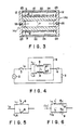
- FIG. 1 is a cross sectional view showing the structure of a first embodiment of a superconducting switch according to this invention;
- FIG. 2 is a perspective view showing the winding state of two superconducting coils;
- FIG. 3 is a cross sectional view showing the structure of a second embodiment of a superconducting switch according to this invention;
- FIG. 4 is a circuit diagram for explaining the operation in the first and second embodiments of this invention;
- FIG. 5 is an equivalent circuit diagram at the time of a normal operation of the superconducting switch according to this invention;
- FIG. 6 is an equivalent circuit diagram at the time of quenching of the superconducting switch according to this invention;
- FIG. 7A is a graph showing current changes at the time of normal operation and at the time of quenching of the superconducting switch according to this invention;
- FIG. 7B is a graph showing impedance changes at the time of normal operation and at the time of quenching of the superconducting switch according to this invention;
- FIG. 8 is a circuit diagram of a first embodiment of a current limiter according to this invention;
- FIG. 9 is a front view partially cut showing the structure of a first embodiment of a current limiter according to this invention;
- FIG. 10 is a model view showing a connection of the current limiting coil and the superconducting switch in the current limiter according to this invention;
- FIG. 11A is a graph showing current changes at the time of normal operation and at the time of quenching operation of the current limiter according to this invention;
- FIG. 11B is a graph showing impedance changes at the time of normal operation and at the time of quenching operation of the current limiter according to this invention;
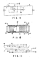
- FIG. 12 is a circuit diagram showing a second embodiment of a current limiter according to this invention;
- FIG. 13 is a front view partially cut showing the structure of a current limiting coil in the second embodiment of the current limiter according to this invention;
- FIG. 14 is a model view showing the coil connection thereof;
- FIG. 15 is a front view partially cut showing the structure of the superconducting switch in the second embodiment of the current limiter according to this invention;
- FIG. 16 is a model view showing the coil connection thereof;
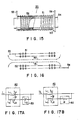
- FIG. 17A is an equivalent circuit diagram showing a normal state operation in the second embodiment of the current limiter according to this invention;
- FIG. 17B is an equivalent circuit diagram showing the current limiting operation in the second embodiment of the current limiter according to this invention;
- FIG. 18A is a graph showing current changes at the time of normal operation and at the time of current limiting operation in the second embodiment of the current limiter according to this invention; and
- FIG. 18B is a graph showing impedance changes at the time of normal operation and at the time of current limiting operation in the second embodiment of the current limiter according to this invention.
- A first embodiment of a superconducting switch according to this invention shown in FIG. 1 will be initially described. A
hollow glass tube 7 is used as a core for winding a superconducting wire thereon. As shown in FIG. 2, a firstsuperconducting coil 8 is wound from one side to the other side on the outer peripheral surface of theglass tube 7 so that it has a predetermined number of turns with a spacing between respective coil sections. Furthermore, a secondsuperconducting coil 9 having the same number of turns as that of the firstsuperconducting coil 8 is wound in a manner that it overlaps with the firstsuperconducting coil 9 in a direction opposite to the winding direction of the firstsuperconducting coil 8. This is a sort of non-inductive winding adapted to produce no electromagnetic induction, and which is known as a so-called AP (Ayrton Perry) winding. Asuperconducting coil body 10 is thus formed. Insulating caps 14 each consisting of an insertion portion 11 and alarge diameter portion 12, and having a clamping or lockinghole 13 are fitted into opening portions of both ends of theglass tube 7, respectively. Terminal plates 15 are put between thelarge diameter portions 12 and both end surfaces ofglass tube 7, respectively. Furthermore,terminal pieces 16 are secured on the opposite sides of the terminal plate 15 in a manner that both ends of theglass tube 7 are fitted into theterminal pieces 16, respectively. Theterminal piece 16 may be an annular member surrounding theglass tube 7, or may be a member holding a plurality of portions of the outer peripheral surfaces of theglass tube 7. Respective both ends of the first and secondsuperconducting coils terminal pieces 16 and electrically conducts to the terminal plate 15.Bushings 17 are inserted into the clamping holes 13 of the respective insulatingcaps 14. A clampingbolt 18 is inserted from one insulatingcap 14 toward the other insulatingcap 14 through thesebushings 17. The both end portions of the clampingbolt 18 projecting from respective insulating caps are clamped by nuts throughfitting plates 19 put between the insulatingcaps 14 and the nuts 20, respectively. Onefitting plate 19 and the insulatingcap 14 are secured by afitting pin 21 so that thesuperconducting body 10 rotates about the clampingbolt 18. It is to be noted that since the first and secondsuperconducting coils superconducting coils - Referring to Fig. 3, there is shown in a second embodiment of a superconducting switch according to this invention. Since this
current limiter 6 is of the same structure as that of the embodiment which has been described with reference to FIG. 1, those corresponding portions are respectively designated by the same reference numerals and their detailed explanation will be omitted. In the case of this embodiment, aconductor cap 14a is used in place of the insulating cap which has been described in the first embodiment of this invention. Theconductor cap 14a includes large diameter portions formed so that they are larger than the outer diameter of thesuperconducting coil body 10, and insertion portions 11 inserted into the both opening portions of theglass tube 7. An outerperipheral wall member 22 is provided between opposite twolarge diameter portions 12 in a manner that it is spaced from the outer peripheral portion of thesuperconducting coil body 10.Sealing members 23 such as silver brazing material are hermetically fitted annularly into respective portions between the end surfaces of the outerperipheral walls 22 and thelarge diameter portions 12. Thus, avacuum chamber 24 is formed between the outer peripheral surface of thesuperconducting col body 10 and the outerperipheral wall member 22. Respective both ends of the first and secondsuperconducting coils conductor cap 14a. The reason why the sealingmember 23 and the outerperipheral wall 22 are formed to have different thicknesses is that displacements received by the sealingmember 23 and the outerperipheral wall 22 are caused to be different from each other, thereby preventing breakage between thelarge diameter portion 12 and the outerperipheral wall 22. Screw holes are formed in the central portions ofrespective conductor caps 14a. The other conductor may be screw-connected to thescrew hole 25. - An example of the operation serving as a current limiter using the superconducting switch constructed above will be described with reference to FIGS. 4 to 7. As shown in FIG. 4,
superconducting switch 6 is serially connected to the succeeding stage of interrupter 3 of a series circuit includingpower supply 2, interrupter 3, line impedance, andload 5. - When the circuit shown in FIG. 4 is normally operating, a predetermined current i₀ flows in
load 5 through superconducting switching 6. This current i₀ is determined by a voltage E and an entire impedance Z. This entire impedance Z is sum of impedance ZSC ofsuperconducting switch 6, a line impedance Zl and a load impedance ZL. At this time, thesuperconducting switch 6 is in a superconducting state, and a current i₀ is a value in a range lower than a critical current Jcl. The current i₀ separately flows in the first and secondsuperconducting coils superconducting coils superconducting coils superconducting coils superconducting switch 6, a line impedance Zl, and a load impedance ZL (not shown). This current i₀ is delivered to load 5 without undergoing a voltage drop by the first and secondsuperconducting coils - The state produced when short-circuit is produced in the
load 5 will be described in connection with the case of "quenching". When a short-circuit is produced in the circuit, an estimated short-circuit current tf given by E/Zl is going to flow. However, the moment a short circuit exceeds a critical current Jcl, the first and secondsuperconducting coils superconducting coils superconducting coils superconducting coils superconducting coils (ωL′)² + Rc²/2 depending upon the respective resistance values Rc which have been rapidly increased. At this time, currents flowing in the first and secondsuperconducting coils superconducting coils superconducting coils - In the case of the
superconducting switch 6 of this invention shown in FIG. 3, the first and secondsuperconducting coils superconducting coils superconducting coils - The
superconducting switch 6 constructed as above can freely select impedance ZSC′ and currents iT1 and iT2 at the time of quenching by selecting material, number of turns, and wire diameter of the first and secondsuperconducting coils switch 6 can limit a current over a broad range. In addition, since the inductance L can be extremely small and the impedance ZSC set over a broad range at the time of normal operation, a contactless switch can be realized. - It is to be noted that while
glass tube 7 is used as the insulating core in the above-mentioned both embodiments, other insulating materials having heat-resisting property may be used for this purpose. - It is further to be noted that the superconducting switch of this invention can be widely applied not only as a current limiter, but also as a switch of which state changes by an increase in current.
- FIG. 8 is a circuit diagram showing the configuration of a first embodiment of a current limiter according to this invention in conjunction with its application. Referring to this figure, an
interrupter 2, acurrent limiter 30, and aline impedance 4 are inserted into one line as an electric path connecting an a.c.power source 1 and a load. In this embodiment, thecurrent limiter 30 comprises asuperconducting coil 31 wound so as to have an inductance sufficient to suppress a current in the line to a value lower than a limit value and asuperconducting switch 32 connected in parallel with thesuperconducting switch 31, wherein thesuperconducting switch 32 includes two coils subjected to non-inductive AP winding so that quantities of flux produced by these coils cancel each other to provide substantially zero inductance, and has a critical current value smaller than that of thesuperconducting coil 31. - FIG. 9 is a schematic view showing an actual configuration of the
superconducting coil 31 and thesuperconducting switch 32. Thesuperconducting coil 31 is wound on abobbin 33, and the coils of thesuperconducting switch 32 are wound on abobbin 34 disposed in a hollow portion of thebobbin 33. Accordingly, thesuperconducting switch 31 wound on the common core within a magnetic field produced by thesuperconducting coil 31. Respective coil ends are connected commonly to theterminals 35 and 36. - The operation of this embodiment constructed above will be described.
- When the
superconducting coil 31 and thesuperconducting switch 32 are both in a superconducting state, thesuperconducting coil 31 exhibits a relatively large impedance by its inductance with respect to a current flowing in the line, whereas thesuperconducting switch 32 exhibits substantially zero impedance because it is non-inductive. FIG. 10 is a model view for explaining the above phenomenon. Assuming that a current i₀ in a direction indicated by an arrow flows in thesuperconducting coil 31 and thesuperconducting switch 32, magnetic flux φ₀ is produced by thesuperconducting coil 31 to have an impedance corresponding to the inductance. In contrast, quantities of magnetic flux φ₁ and φ₂ produced by the AP-wound coils of thesuperconducting switch 32 cancel each other, so that impedance becomes substantially equal to zero. - Assuming that there is no failure on the
load 5 side and a current i₀ having an ordinary amplitude flows in theload 5, when a current flowing in thesuperconducting coil 31 and a current flowing in thesuperconducting switch 32 are designated by iL1 and iL2, respectively, the following relationship holds:
i₀ = iL1 + iL2 (1)
iL1 « iL2 (2) - Accordingly, most of the current i₀ in the line flows into the
superconducting switch 32. In addition, because the resistance value is equal to zero, a voltage drop produced by flowing of the current i₀ is equal to substantially zero. - When an overcurrent flows in the line due to short circuit failure, etc. of the
load 5 and the value thereof exceeds above a critical current value Jcl of thesuperconducting switch 32, thesuperconducting switch 32 is momentarily quenched, resulting a resistor having an extremely large resistance. As a result, most of the current which has flowed in thesuperconducting switch 32 communicates into thesuperconducting coil 32. - Both currents have a relationship expressed as the following equation:
iL1 « iL2 (3) - Accordingly, the line current is limited to a limit value by the inductance of the
superconducting coil 31. In this case, since a current iL2 flowing in thesuperconducting switch 32 is extremely small, a power loss dissipated as heat is suppressed to an extremely small value. - FIGS. 11A and 11B show how the current i and the impedance ZSC of the current limiter vary at the time of normal operation and at the time of current limiting operation. Namely, at the time of normal operation, the impedance ZSC of the
current limiter 30 is extremely small, so the current i₀ in the line is kept normal mainly by the impedance Z of the load. On the other hand, when a short-circuit occurs in the load, an estimated short-circuit current if attempts to flow in the line. However, the moment the line current exceeds the critical current value Jcl of thesuperconducting switch 32, the impedance of the current limiter is increased as described above, so the short-circuit current is limited to a current value iL2 lower than a limit value. - In this case, the critical current value Jc2 of the
superconducting coil 31 is set to a value larger than the current limit value of the line. Furthermore, thecurrent limiter 30 is cooled by interrupting the line by theinterrupter 2, thus readily returning to a steady state. - Since two superconducting coils are disposed using the core common thereto in the above-described embodiment, the current limiter becomes considerably compact and is easily held in a superconducting state. However, even if these superconducting coils are disposed away from each other, the above-described current limiting operation can be performed.
- As just described above, in accordance with this embodiment, superconducting coils are employed and such superconducting coils are arranged using the core common to the both coils. Thus, simplified construction and miniaturization of the current limiter are realized, and high speed response and reliable line protection can be performed.
- FIG. 12 is a circuit diagram showing the configuration of a second embodiment of a current limiter according to this invention in conjunction with its application. Referring to this figure, an
interrupter 2, a current limiter comprising asuperconducting reactor 40 and asuperconducting switch 50, and aline impedance 4 are inserted into one line as an electric path connecting an a.c.power source 1 and aload 5. In this embodiment, thesuperconducting reactor 40 has an inductance to suppress a current in the line to a value lower than a limit value. Thesuperconducting reactor 40 is composed of asuperconducting coil 41 having a critical current value larger than a current limit value, and asuperconducting coil 42 wound on the same bobbin of that of thesuperconducting coil 41. When thiscoil 42 is inserted in parallel into the line, it produces the same magnitude of magnetomotive force as that of thecoil 41. Thus, quantities of magnetic flux produced by thesecoils superconducting switch 50 is constructed as a superconducting coil wound non-inductively and is serially connected to thesuperconducting coil 42. - FIG. 13 is a schematic view showing an actual configuration of the
superconducting reactor 40. Thesuperconducting coil 41 and thesuperconducting coil 42 are wound on thebobbins superconducting coil 42 is wound on the common core insidesuperconducting coil 41. Respective one ends of both coils are connected in common to a terminal 45. The other end of thesuperconducting coil 42 and the other end of thesuperconducting coil 42 are connected toterminals reference numeral 48 denotes a spacer for holding insulating material between theterminals - FIG. 14 is a view showing the internal connection and behavior of magnetic flux of the
superconducting reactor 50. There is provided an arrangement such that when the superconducting coils 41 and 42 are connected in parallel with the line, magnetic flux φ₁ produced on thesuperconducting coil 41 and magentic flux φ₂ produced on thesuperconducting coil 42 cancel each other. - FIG. 15 is a view showing an actual configuration of the
superconducting switch 50. Thisswitch 50 is composed ofsuperconducting coils bobbins superconducting coil 52 is concentrically disposed inside thesuperconducting coil 51. One end of each of the respective coils are connected in common to a terminal 55, and the other ends thereof are connected commonly to a terminal 56. - FIG. 16 shows a diagram showing the internal connection and the behavior of magentic flux of the
superconducting switch 50. When a current is caused to flow betweenterminals superconducting coil 51 and magnetic flux φ₂ produced on thesuperconducting coil 52 cancel with each other. - The superconducting coils 41 and 42 constituting the superconducting reactor are made up so that their critical current values are larger than the current limit value of the line. Furthermore, the superconducting switch is made up so that it is quenched in correspondence with the increase in the current in the
superconducting coil 52 when there overcurrent in the line. - The operation of the second embodiment constructed above will be described with reference to FIG. 10 as well.
- When a current i₀ flowing in the line is in a normal state, both the
superconducting reactor 40 and thesuperconducting switch 50 are held in a superconducting state. Thus, the resistance values of the superconducting coils 51 and 52 constituting thesuperconducting switch 50 are equal to zero and are in a non-inductive state. Accordingly, the current i₀ branches into the superconducting coils 41 and 42 constituting thesuperconducting reactor 40 to flow as currents iL1 and iL2 in these coils, respectively. The respective magnetic flux produced thereby cancel with each other. Thesecoils - FIG. 17A is an equivalent circuit thereof. The
superconducting switch 50 functions as an element having only a very small leakage inductance. Furthermore, thesuperconducting reactor 40 functions as an element having only a mutual inductance -M. - When an estimated short-circuit current if determined by a power supply voltage E and a line impedance Zl attempts to flow as a result of the fact that a failure such as a load short-circuit occurs, a current flowing in the
superconducting switch 50 also increases according as the above current if increases. The superconducting coils 41 and 42 constituting thesuperconducting switch 50 have a critical current value Jcl corresponding to current values being increasing of thesecoils superconducting coil 41 exceeds above this current value Jcl, it is quenched, so a current iL2 which has flowed in thesuperconducting coil 42 communicates into thesuperconducting coil 41. As a result, most of a current flowing in the line flows into thesuperconducting coil 41. Accordingly, thesuperconducting reactor 40 will have a large inductance by magnetic flux φ₁ produced by thesuperconducting coil 41. FIG. 17B shows an equivalent circuit in such a case. Thesuperconducting switch 50 changes to an element having an extremely large value R, and the line current i₀ is limited by the self-inductance of thesuperconducting coil 41. - As just described above, the current limiting circuit according to the second embodiment is constructed so that its impedance is equal to substantially zero with respect to a normal line current, and it functions as a reactor with respect to an overcurrent, therefore to limit a line current.
- FIGS. 18A and 18B show how the current i₀ and the impedance ZSC of the current limiter vary at the time of normal operation and at the time of current limiting operation. Namely, at the time of normal operation, the impedance ZSC of the current limiter is extremely small, so that the line current i₀ is kept normal mainly by the load impedance Zl. In contrast, when a load short circuit occurs, an estimated short-circuit current If attempts to flow in the line. However, when the line current increases to a value of Jq, the current flowing in the
superconducting switch 50 exceeds above the critical current value Jcl. At this moment, the impedance of thesuperconducting reactor 40 increases to a value Z′SC. As a result, the short-circuit current is limited to a value lower than a limit value. - As just described above, also in accordance with this embodiment, superconducting coils are employed and such superconducting coils are arranged using the core common to both the coils. Thus, simplified construction and miniaturization of the current limiter are realized, and high speed response and reliable line protection can be performed.
- Reference signs in the claims are intended for better understanding and shall not limit the scope.
Claims (10)
cylindrical core means (7);
a first superconducting coil(8) wound on the outer peripheral surface of said core means from one side thereof to the other side thereof, and having a first critical current value, wherein when a current above said critical current value flows, the resistance value of said first superconducting coil changes to a first high resistance value in a normal conducting state;
a second superconducting coil (9) wound on the outer peripheral surface of said core means from one side thereof to the other side thereof so as to overlap with said first superconducting coil, and having substantially the same critical current value as that of said first superconducting coil, wherein when a current above critical current value flows, the resistance value of said second superconducting coil changes to a second high resistance value in a normal conducting state; and
connection means (15, 16) for connecting in parallel said first and second superconducting coils so as to produce magnetomotive forces which are the same in the magnitude and are opposite to each other in direction;
said superconducting switch being connected in series with a load in an electric path, wherein an overcurrent above said critical current value flows in said electric path, said superconducting switch is quenched, so the resistance value thereof changes to a resultant resistance value of said first and second high resistance values as a whole.
cylindrical core means (34);
a first superconducting coil (31) wound on the outer peripheral surface of said core means from one side thereof to the other side thereof, and having a first critical current value, wherein when a current above said critical current value flows, the resistance value of said first superconducting coil changes to a first high resistance value in a normal conducting state;
switch means (32) formed non-inductive disposed within a magnetic field produced by said first superconducting coil, and having a second critical current value corresponding to an overcurrent value smaller than said first critical current value, wherein when a current above said second critical current value flows, said switch means changes to a normal conducting state; and
connection means (35, 36) for connecting in parallel said first superconducting coil and said switch means;
said current limiter being connected in series with a load in an electric path, wherein when an overcurrent above said second critical current value flows in said electric path, said current limiter is operative to limit this overcurrent.
cylindrical core means (44);
a first superconducting coil (41) wound on the outer peripheral surface of said core means from one side thereof to the other side thereof, and having a first critical current value, wherein when a current above said critical current value flows, the resistance value of said first superconducting coil changes to a first high resistance value in a normal conducting state;
a second superconducting coil (42) wound in relation to said first superconducting coil, and having the same magnetomotive force as that of said first superconducting coil; and
connection means (45, 46) for connecting in parallel said first and second superconducting coils so as to produce electromotive forces in directions opposite to each other;
switch means (50) connected in series to one of said first and second superconducting coils, formed non-inductive disposed within a magnetic field produced by said first superconducting coil, and having a second critical current value corresponding to an overcurrent value smaller than said first critical current value, wherein when a current above said second critical current value flows, said switch means change to a normal conducting state;
said current limiter being connected in series with a load in an electric path, wherein when an overcurrent above said second critical current value flows in said electric path, said current limiter is operative to limit this overcurrent.
Applications Claiming Priority (4)
| Application Number | Priority Date | Filing Date | Title |
|---|---|---|---|
| JP63174251A JP2935235B2 (en) | 1988-07-13 | 1988-07-13 | Current limiter |
| JP174251/88 | 1988-07-13 | ||
| JP253315/88 | 1988-10-07 | ||
| JP63253315A JP2901068B2 (en) | 1988-10-07 | 1988-10-07 | Current limiting device |
Publications (3)
| Publication Number | Publication Date |
|---|---|
| EP0350916A2 true EP0350916A2 (en) | 1990-01-17 |
| EP0350916A3 EP0350916A3 (en) | 1991-01-02 |
| EP0350916B1 EP0350916B1 (en) | 1994-01-19 |
Family
ID=26495936
Family Applications (1)
| Application Number | Title | Priority Date | Filing Date |
|---|---|---|---|
| EP89112845A Expired - Lifetime EP0350916B1 (en) | 1988-07-13 | 1989-07-13 | Superconducting switch and current limiter using such a switch |
Country Status (3)
| Country | Link |
|---|---|
| US (1) | US5021914A (en) |
| EP (1) | EP0350916B1 (en) |
| DE (1) | DE68912431T2 (en) |
Cited By (8)
| Publication number | Priority date | Publication date | Assignee | Title |
|---|---|---|---|---|
| FR2661288A1 (en) * | 1990-04-24 | 1991-10-25 | Alsthom Gec | Hybrid current limiter |
| FR2663475A2 (en) * | 1990-04-24 | 1991-12-20 | Alsthom Gec | Hybrid current limiter |
| EP0454589A3 (en) * | 1990-04-27 | 1992-01-22 | Railway Technical Research Institute | Switch for controlling current flow in superconductors |
| EP0464679A3 (en) * | 1990-06-28 | 1992-10-21 | The Tokyo Electric Power Co., Inc. | Superconducting ac current limiter equipped with quick-recoverable trigger coils |
| EP0523374A1 (en) * | 1991-06-18 | 1993-01-20 | Hoechst Aktiengesellschaft | Resistive current limiter |
| FR2690288A1 (en) * | 1992-04-15 | 1993-10-22 | Alsthom Gec | Superconductor current limiter for use at very high voltage - has numerous pairs of spools in series with very weak inductances each composed of two rolls electrically in parallel |
| US20120264613A1 (en) * | 2011-04-15 | 2012-10-18 | Varian Semiconductor Equipment Associates, Inc. | Fault Current Limited System with Current Splitting Device |
| WO2015022423A1 (en) | 2013-08-16 | 2015-02-19 | Energy Technologies Institute Llp | Device for a current limiter and a current limiter comprising said device |
Families Citing this family (20)
| Publication number | Priority date | Publication date | Assignee | Title |
|---|---|---|---|---|
| DE69010770T2 (en) * | 1989-05-22 | 1995-03-02 | Toshiba Kawasaki Kk | Current limiting device. |
| JPH04359626A (en) * | 1991-06-04 | 1992-12-11 | Tokyo Electric Power Co Inc:The | Current limiter |
| DE4119983A1 (en) * | 1991-06-18 | 1992-12-24 | Hoechst Ag | RESISTIVE CURRENT LIMITER AND METHOD FOR THE PRODUCTION THEREOF |
| JPH05300644A (en) * | 1992-04-20 | 1993-11-12 | Tokyo Electric Power Co Inc:The | Superconducting current limiter |
| JP3470809B2 (en) * | 1992-12-02 | 2003-11-25 | イーエムシー コーポレイション | Inrush current limiter |
| US5361055A (en) * | 1993-12-17 | 1994-11-01 | General Dynamics Corporation | Persistent protective switch for superconductive magnets |
| GB9613266D0 (en) * | 1996-06-25 | 1996-08-28 | Oxford Instr Public Limited Co | Current limiting device |
| US5892644A (en) * | 1997-11-20 | 1999-04-06 | The University Of Chicago | Passive fault current limiting device |
| US6397032B1 (en) | 1999-09-10 | 2002-05-28 | Canon Kabushiki Kaisha | Image forming apparatus including a developer bearing member having multiple layers |
| US20020018327A1 (en) * | 2000-07-10 | 2002-02-14 | Walker Michael S. | Multi-winding fault-current limiter coil with flux shaper and cooling for use in an electrical power transmission/distribution application |
| KR101028817B1 (en) | 2005-05-25 | 2011-04-12 | 현대중공업 주식회사 | Induction Wire Type High Temperature Superconducting Current Limiter |
| KR100717351B1 (en) * | 2006-03-02 | 2007-05-11 | 연세대학교 산학협력단 | Current limiter with superconducting bypass reactor for simultaneous quench |
| KR100802312B1 (en) * | 2006-10-25 | 2008-02-11 | 엘에스산전 주식회사 | Half-wave non-limiting superconducting fault current limiter with integrated high speed switch module |
| US20090156409A1 (en) * | 2007-12-17 | 2009-06-18 | Superpower, Inc. | Fault current limiter incorporating a superconducting article |
| GB2457706B (en) * | 2008-02-22 | 2010-03-10 | Siemens Magnet Technology Ltd | Coil energisation apparatus and method of energising a superconductive coil |
| US20140085757A1 (en) * | 2012-09-21 | 2014-03-27 | Enphase Energy, Inc. | Surge blocking inductor |
| US9583255B2 (en) | 2012-09-21 | 2017-02-28 | Enphase Energy, Inc. | Surge blocking inductor |
| JP6329422B2 (en) * | 2014-04-21 | 2018-05-23 | オリンパス株式会社 | Medical instruments, insertion aids, and medical systems |
| CN106961097A (en) * | 2017-05-23 | 2017-07-18 | 苏州木山云智能科技有限公司 | A kind of built-in pillar current limiter |
| CN106972472A (en) * | 2017-05-23 | 2017-07-21 | 苏州木山云智能科技有限公司 | A kind of current limiter |
Family Cites Families (6)
| Publication number | Priority date | Publication date | Assignee | Title |
|---|---|---|---|---|
| DE1563335B2 (en) * | 1966-04-26 | 1971-04-29 | Siemens AG, 1000 Berlin u 8000 München | COIL WITH VARIABLE INDUCTIVITY AS A CURRENT LIMITING DEVICE FOR ENERGY TRANSFER SYSTEMS |
| US4271585A (en) * | 1977-12-28 | 1981-06-09 | The United States Of America As Represented By The United States Department Of Energy | Method of constructing a superconducting magnet |
| US4586017A (en) * | 1983-09-12 | 1986-04-29 | General Electric Company | Persistent current switch for high energy superconductive solenoids |
| FR2600206B1 (en) * | 1985-12-05 | 1988-08-19 | Alsthom | AC CURRENT LIMITER |
| US4841268A (en) * | 1987-09-28 | 1989-06-20 | General Atomics | MRI Magnet system with permanently installed power leads |
| US4764837A (en) * | 1987-11-16 | 1988-08-16 | General Electric Company | Superconductive circuit for controlling quench events |
-
1989
- 1989-07-13 DE DE68912431T patent/DE68912431T2/en not_active Expired - Fee Related
- 1989-07-13 EP EP89112845A patent/EP0350916B1/en not_active Expired - Lifetime
- 1989-07-13 US US07/379,117 patent/US5021914A/en not_active Expired - Fee Related
Cited By (21)
| Publication number | Priority date | Publication date | Assignee | Title |
|---|---|---|---|---|
| FR2661288A1 (en) * | 1990-04-24 | 1991-10-25 | Alsthom Gec | Hybrid current limiter |
| FR2663475A2 (en) * | 1990-04-24 | 1991-12-20 | Alsthom Gec | Hybrid current limiter |
| US5153804A (en) * | 1990-04-24 | 1992-10-06 | Gec Alsthom Sa | Hybrid current limiter having superconductor windings |
| EP0454589A3 (en) * | 1990-04-27 | 1992-01-22 | Railway Technical Research Institute | Switch for controlling current flow in superconductors |
| US5204650A (en) * | 1990-04-27 | 1993-04-20 | Railway Technical Research Institute | Switch for controlling current flow in superconductors |
| EP0464679A3 (en) * | 1990-06-28 | 1992-10-21 | The Tokyo Electric Power Co., Inc. | Superconducting ac current limiter equipped with quick-recoverable trigger coils |
| US5225956A (en) * | 1990-06-28 | 1993-07-06 | The Tokyo Electric Power Company, Incorporated | Superconducting ac current limiter equipped with quick-recoverable trigger coils |
| EP0523374A1 (en) * | 1991-06-18 | 1993-01-20 | Hoechst Aktiengesellschaft | Resistive current limiter |
| FR2690288A1 (en) * | 1992-04-15 | 1993-10-22 | Alsthom Gec | Superconductor current limiter for use at very high voltage - has numerous pairs of spools in series with very weak inductances each composed of two rolls electrically in parallel |
| WO2012142201A1 (en) * | 2011-04-15 | 2012-10-18 | Varian Semiconductor Equipment Associates, Inc. | Fault current limiter system with current splitting device |
| US20120264613A1 (en) * | 2011-04-15 | 2012-10-18 | Varian Semiconductor Equipment Associates, Inc. | Fault Current Limited System with Current Splitting Device |
| US8787999B2 (en) | 2011-04-15 | 2014-07-22 | Varian Semiconductor Equipment Associates, Inc. | Fault current limited system with current splitting device |
| US20140357490A1 (en) * | 2011-04-15 | 2014-12-04 | Varian Semiconductor Equipment Associates, Inc. | Fault current limiter system with current splitting device |
| TWI491133B (en) * | 2011-04-15 | 2015-07-01 | Varian Semiconductor Equipment | Current splitting device, system for carrying current, and fault current limiter system with the current splitting device |
| AU2012242835B2 (en) * | 2011-04-15 | 2016-06-23 | Varian Semiconductor Equipment Associates, Inc. | Current splitting device, system for carrying current, and fault current limiter system with the current splitting device |
| AU2016210745B2 (en) * | 2011-04-15 | 2018-09-06 | Varian Semiconductor Equipment Associates, Inc. | Current splitting device, system for carrying current, and fault current limiter system with the current splitting device |
| WO2015022423A1 (en) | 2013-08-16 | 2015-02-19 | Energy Technologies Institute Llp | Device for a current limiter and a current limiter comprising said device |
| EP3001431A1 (en) * | 2013-08-16 | 2016-03-30 | Energy Technologies Institute LLP | Device for a current limiter and a current limiter comprising said device |
| CN105706191A (en) * | 2013-08-16 | 2016-06-22 | 能源技术研究所 | Device for a current limiter and a current limiter comprising said device |
| US10186858B2 (en) | 2013-08-16 | 2019-01-22 | Rolls-Royce Plc | Device for a current limiter and a current limiter comprising said device |
| CN105706191B (en) * | 2013-08-16 | 2019-09-20 | 劳斯莱斯有限公司 | Apparatus for a current limiter and a current limiter including the same |
Also Published As
| Publication number | Publication date |
|---|---|
| US5021914A (en) | 1991-06-04 |
| EP0350916A3 (en) | 1991-01-02 |
| DE68912431D1 (en) | 1994-03-03 |
| DE68912431T2 (en) | 1994-07-07 |
| EP0350916B1 (en) | 1994-01-19 |
Similar Documents
| Publication | Publication Date | Title |
|---|---|---|
| EP0350916B1 (en) | Superconducting switch and current limiter using such a switch | |
| US3703664A (en) | Fault current limiter using superconductive element | |
| US5225956A (en) | Superconducting ac current limiter equipped with quick-recoverable trigger coils | |
| US5930095A (en) | Superconducting current limiting device by introducing the air gap in the magnetic core | |
| US5153804A (en) | Hybrid current limiter having superconductor windings | |
| US4910626A (en) | Current limiter | |
| US4812796A (en) | Quench propagation device for a superconducting magnet | |
| US6809910B1 (en) | Method and apparatus to trigger superconductors in current limiting devices | |
| EP0567293A1 (en) | Superconducting current limiting device | |
| US5334964A (en) | Current limiting choke coil | |
| US5821496A (en) | Method of controlling transient recovery voltage and gas insulation switch gear using the same | |
| US6300856B1 (en) | Electrical transformer | |
| JP2941833B2 (en) | Superconducting current limiting device | |
| US4358808A (en) | High energy overcurrent protective device | |
| JP2901068B2 (en) | Current limiting device | |
| US4556859A (en) | Method and structure of individually shielded, relay, pickup and holding coils, to reduce the effects of external and internal transients | |
| US7023673B2 (en) | Superconducting shielded core reactor with reduced AC losses | |
| KR101402746B1 (en) | Superconducting fault current limiter having contact switch and using magnetic coupling | |
| Paul et al. | Superconducting fault current limiters based on high Tc superconductors | |
| KR102472477B1 (en) | Protection device for saturated iron-core superconducting fault current limiter | |
| US20250118955A1 (en) | Overcurrent Limiting Unit and Detection Unit and Method for Manufacturing and Method for Operating the Same | |
| JP2716789B2 (en) | Current limiting device | |
| JP2533119B2 (en) | Superconducting device for short circuit suppression | |
| JP2935235B2 (en) | Current limiter | |
| KR102349708B1 (en) | Core structure for SI-SFCL |
Legal Events
| Date | Code | Title | Description |
|---|---|---|---|
| PUAI | Public reference made under article 153(3) epc to a published international application that has entered the european phase |
Free format text: ORIGINAL CODE: 0009012 |
|
| 17P | Request for examination filed |
Effective date: 19890713 |
|
| AK | Designated contracting states |
Kind code of ref document: A2 Designated state(s): DE FR GB |
|
| PUAL | Search report despatched |
Free format text: ORIGINAL CODE: 0009013 |
|
| AK | Designated contracting states |
Kind code of ref document: A3 Designated state(s): DE FR GB |
|
| 17Q | First examination report despatched |
Effective date: 19920818 |
|
| GRAA | (expected) grant |
Free format text: ORIGINAL CODE: 0009210 |
|
| AK | Designated contracting states |
Kind code of ref document: B1 Designated state(s): DE FR GB |
|
| REF | Corresponds to: |
Ref document number: 68912431 Country of ref document: DE Date of ref document: 19940303 |
|
| ET | Fr: translation filed | ||
| PLBE | No opposition filed within time limit |
Free format text: ORIGINAL CODE: 0009261 |
|
| STAA | Information on the status of an ep patent application or granted ep patent |
Free format text: STATUS: NO OPPOSITION FILED WITHIN TIME LIMIT |
|
| 26N | No opposition filed | ||
| REG | Reference to a national code |
Ref country code: GB Ref legal event code: 746 Effective date: 19981015 |
|
| REG | Reference to a national code |
Ref country code: FR Ref legal event code: D6 |
|
| PGFP | Annual fee paid to national office [announced via postgrant information from national office to epo] |
Ref country code: GB Payment date: 19990707 Year of fee payment: 11 |
|
| PGFP | Annual fee paid to national office [announced via postgrant information from national office to epo] |
Ref country code: DE Payment date: 19990716 Year of fee payment: 11 |
|
| PG25 | Lapsed in a contracting state [announced via postgrant information from national office to epo] |
Ref country code: GB Free format text: LAPSE BECAUSE OF NON-PAYMENT OF DUE FEES Effective date: 20000713 |
|
| GBPC | Gb: european patent ceased through non-payment of renewal fee |
Effective date: 20000713 |
|
| PG25 | Lapsed in a contracting state [announced via postgrant information from national office to epo] |
Ref country code: DE Free format text: LAPSE BECAUSE OF NON-PAYMENT OF DUE FEES Effective date: 20010501 |
|
| PGFP | Annual fee paid to national office [announced via postgrant information from national office to epo] |
Ref country code: FR Payment date: 20030711 Year of fee payment: 15 |
|
| PG25 | Lapsed in a contracting state [announced via postgrant information from national office to epo] |
Ref country code: FR Free format text: LAPSE BECAUSE OF NON-PAYMENT OF DUE FEES Effective date: 20050331 |
|
| REG | Reference to a national code |
Ref country code: FR Ref legal event code: ST |