EP0350838A2 - Communication system - Google Patents
Communication system Download PDFInfo
- Publication number
- EP0350838A2 EP0350838A2 EP89112584A EP89112584A EP0350838A2 EP 0350838 A2 EP0350838 A2 EP 0350838A2 EP 89112584 A EP89112584 A EP 89112584A EP 89112584 A EP89112584 A EP 89112584A EP 0350838 A2 EP0350838 A2 EP 0350838A2
- Authority
- EP
- European Patent Office
- Prior art keywords
- unit
- packet
- address
- lock
- communication
- Prior art date
- Legal status (The legal status is an assumption and is not a legal conclusion. Google has not performed a legal analysis and makes no representation as to the accuracy of the status listed.)
- Granted
Links
Images


Classifications
-
- H—ELECTRICITY
- H04—ELECTRIC COMMUNICATION TECHNIQUE
- H04L—TRANSMISSION OF DIGITAL INFORMATION, e.g. TELEGRAPHIC COMMUNICATION
- H04L12/00—Data switching networks
- H04L12/28—Data switching networks characterised by path configuration, e.g. LAN [Local Area Networks] or WAN [Wide Area Networks]
- H04L12/40—Bus networks
- H04L12/407—Bus networks with decentralised control
Landscapes
- Engineering & Computer Science (AREA)
- Computer Networks & Wireless Communication (AREA)
- Signal Processing (AREA)
- Mobile Radio Communication Systems (AREA)
- Communication Control (AREA)
- Selective Calling Equipment (AREA)
Abstract
Description
- This invention relates to a communication system.
- In some known communication networks including a plurality of units or stations connected via a common transmission line, when a first station requires a communication with a second station, the first station transmits a locking (holding) packet to the second station to lock (hold) the second station into a state where the second station accepts a subsequent packet or packets from the first station but rejects any packets from other stations. Upon the receipt of the locking packet, the second station recognizes that the second station is locked by the first station. At an end of the communication, the first station transmits an unlocking (unholding) packet to the second station to release the second station from the locked state. When the second station moves out of the locked state, the second station can accept packets from any stations. During the interval where the second station remains locked by the first station, when a third station transmits a packet to the second station, the transmitted packet is rejected by the second station. The third station is informed by the rejection of the transmitted packet that the second station is held by another station. In some cases, the third station abandons the communication with the second station. In other cases, the third station retransmits the packet to the second station at a moment a predetermined time after the first transmission of the packet.
- In these prior art communication networks, while a first station remains locking a second station, a third station can not communicate with the second station. In addition, since the third station is not previously informed of the expected time of the end of the communication between the first and second stations, the third station tends to wastefully transmit a packet many times.
- It is an object of this invention to provide an efficient communication system.
- A first communication system of this invention comprises first, second, and third communication control units identified by respective different addresses; the first unit comprising means for, in cases where the first unit locks the second unit to communicate with the second unit, storing a data representing a time remaining until the locking of the second unit is released; the second unit comprising means for, in cases where the first unit locks the second unit to communicate with the second unit, storing a data representing the address of the first unit as a lock address corresponding to an address of a unit which locks the second unit; the third unit comprising means for, in cases where the third unit tries to communicate with the second unit and fails the communication with the second unit, connecting with the second unit and reading out the data representative of the lock address from the second unit, means for connecting with the first unit in response to the lock address and reading out the data representative of the lock remaining time from the first unit, and means for retrying to communicate with the second unit after the lock remaining time elapses.
- A second communication system of this invention comprises first, second, and third communication control units identified by respective different addresses; the second unit comprising means for, in cases where the first unit locks the second unit, storing a data representing the address of the first unit as a lock address corresponding to an address of a unit which locks the second unit; the third unit comprising means for, in cases where the third unit tries to communicate with the second unit and fails the communication with the second unit, connecting with the second unit and reading out the data representative of the lock address from the second unit, means for connecting with the first unit in response to the lock address and requiring the first unit to inform the third unit that the first unit unlocks the second unit; the first unit comprising means responsive to the requiring by the third unit for, when the first unit unlocks the second unit, informing the third unit that the second unit is unlocked; the third unit further comprising means for retrying to communicate with the second unit when the third unit is informed that the second unit is unlocked.
-
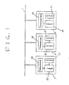
- Fig. 1 is a block diagram of a communication system according to a first embodiment of this invention.
- Fig. 2 is a diagram of a memory of Fig. 1.
- Fig. 3 is a diagram of a communication packet used in the communication system of Fig. 1.
- Fig. 4 is a diagram showing the relation between the bit state and the contents of the control field of the communication packet of Fig. 3.
- Figs. 5 and 6 are diagrams showing different operations of the communication system of Fig. 1 respectively.
- Fig. 7 is a diagram of a memory in a communication system according to a second embodiment of this invention.
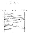
- Fig. 8 is a diagram showing operation of the communication system of the second embodiment.
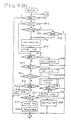
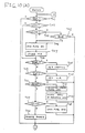
- Fig. 9 is a flowchart of a program operating a controller in the communication system of Fig. 1.
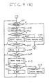
- Fig. 10 is a flowchart of a program operating a controller in the communication system of the second embodiment.
- With reference to Fig. 1, a communication network includes an
information transmission line 1 and a plurality of stations orcommunication control units transmission line 1. The units 2-4 are similar in structure and function. The units 2-4 are denoted by different addresses so that they can be identified. Thecommunication control unit 2 includes apacket transceiver 20, amemory 21, and acontroller 22. Thepacket transceiver 20 is directly coupled to thetransmission line 1. The packet transceiver 20 transmits and receives packets to and from thetransmission line 1. Thememory 21 stores slave status information data related to lock conditions and time information data related to a locking process. Thecontroller 22 is connected between thepacket transceiver 20 and thememory 21. Thecontroller 22 controls thepacket transceiver 20 and thememory 21. Thecontroller 22 includes a microcomputer operating in accordance with a program stored in an internal ROM. Similarly, thecommunication control unit 3 includes apacket transceiver 30, a memory 31, and acontroller 32. Thecommunication control unit 4 also includes apacket transceiver 40, amemory 41, and acontroller 42. - The
memory 21 has segments for storingrespective information data memory 21. For example, an address "a", is allotted to the memory segment for theinformation data 212 while an address "b" is allotted to the memory segment for theinformation data 213. Theinformation data 210 relates to a slave status representing whether or not theunit 2 is in a locked (held) state. Theinformation data 211 relates to a locking-unit address (a lock address), that is, an address of a unit which locks (holds) theunit 2. Theinformation data 212 relates to a locked-unit address (a locked address), that is, an address of a unit which is locked by theunit 2. Theinformation data 213 relates to a lock remainder or remaining time, that is, a time remaining until theunit 2 releases another unit from its locked state. The lock remaining time corresponds to the remainder of the time during which theunit 2 continues to lock another unit. Thememories 31 and 41 are similar to thememory 21. - Fig. 3 shows a format of a communication packet. The packet includes a sequence of a
start bit 51, amaster address 52, aparity bit 53, aslave address 54, a parity bit 55, an ack (acknowledgment) bit 56, acontrol field 57, aparity bit 58, anack bit 59, and adata field 60. Thestart bit 51 represents a start of the packet. Themaster address 52 corresponds to an address of a unit from which the packet is transmitted. Theparity bit 53 is associated with themaster address 52. Theslave address 54 corresponds to an address of a unit to which the packet is directed. The parity bit 55 and the ack bit 56 are associated with theslave address 54. Thecontrol field 57 represents the type of an instruction or control. Theparity bit 58 and theack bit 59 are associated with thecontrol field 57. Thedata field 60 represents the substance of a transmission message. Thedata field 60 includes one or more sets of 1-byte data, a parity bit and an ack bit associated with the data. - Each of the parity bits in the packet is used in the parity check on the associated address, field, or data. In addition, each of the ack bits is used to inform a packet-transmitting unit of whether or not the associated address, field, or data is successfully received by a packet-receiving unit. Specifically, when the address, field, or data is successfully received, the packet-receiving unit returns the ack bit of positive acknowledgment data "0" to the packet-transmitting unit. Otherwise, the packet-receiving unit returns the ack bit of negative acknowledgment data "1" to the packet-transmitting unit. The packet-transmitting unit controls the transmission of the packet in accordance with the acknowledgment data fed from the packet-receiving unit. For example, after the packet-transmitting unit transmits the
slave address 54 and the parity bit 55, the packet-transmitting unit waits the ack bit 56 returned from the packet-receiving unit. After the packet-transmitting unit receives the ack bit 56, the packet-transmitting unit discriminates the content of the ack bit 56. When the ack bit 56 is positive, the packet-transmitting unit transmits thesubsequent control field 57 to the packet-receiving unit. When the ack bit 56 is negative, the packet-transmitting unit performs a suitable action such as a retransmission of the sequence of theslave address 54 and the parity bit 55. - As shown in Fig. 4, the
control field 57 has a sequence of four bits B3, B2, B1, and B1, representing the direction of data transmission, the contents of the control, and the contents of the lock operation. The direction of data transmission is of two types, one corresponding to the case where a transmitting side (a master) reads out data from a receiving side (a slave), the other corresponding to the case where a transmitting side (a master) writes data into a receiving side (a slave). The contents of the control are classified into the reading of a slave status, data, or a lock address, and the writing of a memory address, a command, or data. For example, when a slave receives a data-writing communication packet from a master, the slave accepts data in the data field of the packet and stores the data into a receiver buffer (a memory). When a slave receives a communication packet from a master which instructs the reading of a slave status or a lock address, the slave returnsstatus information 210 or alock address 211 to the master by use of the data field of the packet. When a slave receives a communication packet from a master which instructs the writing of a memory address, the slave recognizes that the address value in the data field of the packet will be read out by a subsequent communication packet, and the slave prepares the data denoted by the address value. The contents of the lock operation is classified into locking, unlocking (releasing the lock), and nonlock. The locking is to lock a communication mate. The unlocking is to unlock a communication mate. The nonlock means that communication will be established regardless of a locked state of a communication mate. - A description will be made on the case where while the
communication control unit 3 remains locking thecommunication control unit 2, thecommunication control unit 4 fetches the information of the lock remaining time from thecommunication control unit 3. As shown in Fig. 5, theunit 3 transmits a communication packet A to theunit 2 via thetransmission line 1, the packet A instructing the locking of theunit 2. In theunit 2, when thepacket transceiver 20 receives the packet A, thepacket transceiver 20 informs thecontroller 22 of the reception of the packet A. The reception of the packet A causes thecontroller 22 to generate information data representing that theunit 2 is locked by theunit 3. Thecontroller 22 stores the information data into thememory 21. Specifically, the address of theunit 3 is written into thelock address segment 211 of thememory 21, and the locked information is written into theslave status segment 210 of thememory 21. In theunit 3, when the transmission of the packet A is successful, thecontroller 32 stores the address of theunit 2 into the lock address segment of the memory 31 and stores lock remaining time data into the related segment of the memory 31. Thecontroller 32 periodically updates the lock remaining time data. It is assumed that, during this interval, theunit 4 transmits a communication packet B to theunit 2. When the transmission of the slave address and the related parity bit is successful, theunit 2 returns an ack bit of the positive answer "0" to theunit 4. In response to the positive ack bit "0", theunit 4 transmits the control field X′B′ of the packet B. The control field X′ B′ represents the instruction of the writing of the locking command. When theunit 2 receives the control field X′ B′ of the communication packet B, thecontroller 22 checks theslave status 210 and thelock address 211 so that thecontroller 22 recognizes the current state where theunit 2 is being locked by theunit 3 and is inhibited from receiving the later part of the packet B. Accordingly, theunit 2 returns an ack bit of the negative answer "1" to theunit 4 subsequently to the parity bit for the control field. When theunit 4 receives the negative ack bit "1", theunit 4 transmits a communication packet C to theunit 2 in order to know the reason for the inhibition of the reception of the later part of the packet B by theunit 2. The packet C has the control field X′0′ designed to read out the slave status from theunit 2. When theunit 2 receives the packet C, thecontroller 22 reads out theslave status information 210 from thememory 21 in response to the contents of the control field of the packet C. Theunit 2 transmits theslave status information 210 to theunit 4 in the data field of the packet C. Theunit 4 is informed by theslave status information 210 that theunit 2 is locked by another communication control unit and is thus inhibited from receiving the later part of the packet B. Accordingly, theunit 4 transmits a communication packet D to theunit 2, the packet D having the control field including the code X′4′X′5′ which instructs the reading of the lock address from theunit 2. When theunit 2 receives the packet D, thecontroller 22 reads out thelock address 211 from thememory 21 in response to the contents of the control field of the packet D. Theunit 2 transmits thelock address 211 to theunit 4 in the data field of the packet D. Theunit 4 is informed by thelock address 211 that theunit 2 is locked by theunit 3. Then, theunit 4 inquires of theunit 3 as to the lock remaining time. Specifically, theunit 4 transmits a communication packet E to theunit 2. The control field of the packet E has an instruction X′8′ of writing the memory address of the lock operation. The data field of the packet E has the address value "b". When theunit 3 receives the packet E, thecontroller 32 reads out the information of the lock remaining time T1 from the segment of the memory 31, which is designated by the address "b", so that the lock remaining time T1 is prepared. Subsequently, theunit 4 transmits a communication packet F to theunit 2. The packet F has the control field X′7′ designed to read out the data of the unlocking operation, that is, the lock remaining time. After theunit 3 receives the control field of the packet F, theunit 3 transmits the previously-prepared lock remaining time T1 to theunit 4 by use of the data field of the packet F. When theunit 4 receives the lock remaining time T1, theunit 4 recognizes that theunit 3 will unlock theunit 2 at the later moment determined by the lock remaining time T1. Accordingly, theunit 4 waits a time equal to or longer than the lock remaining time T1. On the other hand, theunit 3 sequentially transmits subsequent communication packets G and H to theunit 2. When theunit 3 completes the substance of the communication with theunit 2, theunit 3 transmits a unlocking packet I to theunit 2 in order to unlock theunit 2. When theunit 2 receives the packet I, thecontroller 22 changes theslave status 210 in thememory 21 into the unlocked state and clears thelock address 211 in thememory 21 to the empty state in response to the packet I. After theunit 4 waits the time equal to or longer than the lock remaining time T1, theunit 4 retransmits the packet B to theunit 2. When theunit 2 receives the packet B, thecontroller 22 checks theslave status 210 of thememory 21 and recognizes that theunit 2 is not locked. Accordingly, thecontroller 22 instructs thepacket transceiver 20 to return the positive ack bit "0" to theunit 4 via thetransmission line 1. Theunit 4 transmits the data field of the packet B to theunit 2 in response to the positive ack bit "0". - A description will be made on the case where while the
communication control unit 3 locks thecommunication control unit 2 but a malfunction or another cause makes thecommunication control unit 3 incapable of unlocking thecommunication control unit 2, thecommunication control unit 4 performs the communication with thecommunication control unit 2. As shown in Fig. 6, the communication packets A, B, C, and D are transmitted among theunits unit 3 locks theunit 2. It is assumed that a malfunction or another cause makes theunit 3 incapable of performing communication while theunit 2 remains locked. When theunit 4 transmits the communication packet E to theunit 3, theunit 3 returns the negative ack bit "1" to theunit 4 subsequently to the slave address of the packet E. Therefore, the communication between theunits unit 4 retransmits the packet E to theunit 3, and theunit 4 receives again the negative ack bit "1" from theunit 3. Theunit 4 understands from the second reception of the negative ack bit "1" that a malfunction or another problem occurs in theunit 3. Then, theunit 4 transmits a communication packet J to theunit 2. The master address of the packet J corresponds to the address of theunit 3. The control field of the packet J represents an instruction X′A′ of writing a locking command. The data field of the packet J represents that theunit 3 is incapable of communication. When theunit 2 receives the packet J, theunit 2 is informed by the packet J that theunit 3 is incapable of communication. Theunit 2 transmits a communication packet K to theunit 3 in order to confirm that theunit 3 is incapable of communication. When theunit 2 receives the negative ack bit "1" from theunit 3 subsequently to the slave address of the packet K, theunit 2 confirms that theunit 3 is incapable of communication. In this case, theunit 2 cancels the locked state by itself. Specifically, thecontroller 22 changes theslave status 210 in thememory 21 into the unlocked state and clears the lock address of thememory 21 to the empty state. Then, theunit 4 retransmits the packet B to theunit 2 as in the case of Fig. 5. - The communication packet J may be designed as follows. The master address of the communication packet J corresponds to the address of the
unit 4. The control field of the packet J enables the confirmation of a newly-defined nonlock state. The data field of the packet J represents that theunit 3 is incapable of communication. - Each of the
controllers communication control units - As shown in Fig. 9, a
first step 501 of the program determines whether or not a packet is inputted (received). When the packet is inputted, the program advances to astep 502. When the packet is not inputted, the program jumps to astep 601. - The
step 502 determines whether or not the control field of the input packet represents locking. When the control field of the input packet represents locking, the program advances to astep 503. When the control field of the input packet does not represent locking, the program jumps to astep 504. - The
step 503 determines whether or not the present communication control unit is already in the locked state. When the unit is already in the locked state, the program advances to astep 505. when the unit is not in the locked state, the program advances to astep 506. - The
step 505 determines whether or not the master address (MA) of the input packet agrees with the lock address (LA) stored in the memory of the present unit. When the master address agrees (MA) with the lock address (LA), the program advances to thestep 506. When the master address (MA) does not agree with the lock address (LA), the program jumps to thestep 601. - The
step 506 makes on the flag in the slave status which represents that the unit is locked. Astep 507 following thestep 506 stores the master address (MA) of the input packet into the memory as a lock address. After thestep 507, the program advances to thestep 504. - The
step 504 determines whether or not the control field of the input packet represents the reading of the slave status. When the control field represents the reading of the slave status, the program advances to thestep 601 via astep 508 which reads out the slave status from the memory and which sets the slave status into the transceiver. When the control field does not represent the reading of the slave status, the program advances to astep 509. - The
step 509 determines whether or not the control field of the input packet represents the reading of the lock address (LA). When the control field represents the reading of the lock address (MA), the program advances to thestep 601 via astep 510 which reads out the lock address from the memory and sets the lock address into the transceiver. When the control field does not represent the reading of the lock address, the program advances to astep 511. - The
step 511 determines whether or not the control field of the input packet requires unlocking (releasing the lock). When the control field requires unlocking, the program advances to a step 512. When the control field does not require unlocking, the program advances to astep 513. - The step 512 transmits the lock confirmation packet to the communication control unit which performs the locking. A step 514 following the step 512 determines whether or not the communication of the lock confirmation packet is successful. When the communication is successful, the program advances to the
step 601. When the communication is not successful, the program advances to astep 515 which unlocks or releases the unit from the locked state by itself. After thestep 515, the program advances to thestep 601. - The
step 513 determines whether or not the control field of the input packet represents the reading of the lock remaining time. When the control field represents the reading of the lock remaining time, the program advances to thestep 601 via astep 516 which reads out the lock remaining time from the memory and sets the lock remaining time into the transceiver. When the control field does not represent the reading of the lock remaining time, the program advances to astep 517. - The
step 517 determines whether or not the control field of the input packet represents unlocking (releasing the lock). When the control field represents unlocking, the program advances to thestep 601 via astep 518 which makes off the flag in the slave status which represents that the unit is locked. When the control field does not represent unlocking, the program advances to astep 519 which stores the data processing time into the memory as the lock remaining time. - After the
step 519, the program advances to thestep 601 via astep 520 which allows the reception of the data field of the input packet. - The
step 601 determines whether or not a transmission requirement is present. When a transmission requirement is absent, the program returns to thestep 501. When a transmission requirement is present, the program advances to astep 602. Thestep 602 transmits the lock-requiring packet to the designated or target communication control unit. - A
step 603 following thestep 602 determines whether or not the communication of the lock-requiring packet is successful. When the communication is successful, the program returns to thestep 501 via astep 604 which cancels the transmission requirement. When the communication is not successful, the program advances to astep 605 which reads out the slave status from the designated unit. - A
step 606 following thestep 605 determines whether or not the designated unit is in the locked state by referring to the slave states read out by thestep 605. When the designated unit is not in the locked state, the program returns to thestep 601. When the designated unit is in the locked state, the program advances to astep 607 which reads out the lock address from the designated unit. - A
step 608 following thestep 607 determines whether or not the lock address (LA) read out by thestep 607 agrees with the address (UA) of the present unit. When the lock address (LA) agrees with the address (UA) of the present unit, the program returns to thestep 601. When the lock address (LA) does not agree with the address (UA) of the present unit, the program advances to astep 609. - The
step 609 transmits a packet to the unit which performs the locking, the packet allowing the reading of the lock remaining time from the locking unit. Astep 610 following thestep 609 determines whether or not the communication of the time-reading packet is successful. When the communication is successful, the program advances to a step 611 which waits the time T1 corresponding to the lock remaining time. When the communication is not successful, the program advances to astep 612 which requires the locked unit to release the locked state by itself. After thesteps 611 and 612, the program returns to thestep 601. - Figs. 7 and 8 relate to a second embodiment of this invention which is similar to the embodiment of Figs. 1-6 except for the following design changes.
- As shown in Fig. 7, the
memory 21 has segments for storingrespective information data memory 21. Theinformation data 210 relates to a slave status representing whether or not theunit 2 is in a locked (held) state. Theinformation data 211 relates to an address of a unit which locks (holds) theunit 2. Theinformation data 214 relates to an address of a unit which is to be informed that theunit 2 is unlocked. The memories 31 and 41 (see Fig. 1) are similar to thememory 21. - A description will be made on the case where while the communication control unit 3 (see Fig. 1) remains locking the communication control unit 2 (see Fig. 1), the communication control unit 4 (see Fig. 1) obtains information from the
communication control unit 3, the information representing a timing at which communication with thecommunication control unit 2 becomes allowed. As shown in Fig. 8, theunit 3 transmits a communication packet A to theunit 2 via thetransmission line 1, the packet A instructing the locking of theunit 2. In theunit 2, when thepacket transceiver 20 receives the packet A, thepacket transceiver 20 informs thecontroller 22 of the reception of the packet A. The reception of the packet A causes thecontroller 22 to generate information data representing that theunit 2 is locked by theunit 3. Thecontroller 22 stores the information data into the memory. 21. Specifically, the address of theunit 3 is written into thelock address segment 211 of thememory 21, and the locked information is written into theslave status segment 210 of thememory 21. It is assumed that, under these conditions, theunit 4 sequentially transmits communication packets B, C, and D to theunit 2. The processing of the packet B, C, and D is similar to that in the case of Fig. 5. When theunit 4 recognizes that theunit 2 is locked by theunit 3, theunit 4 transmits a communication packet L to theunit 3. The communication packet L is designed to require theunit 3 to inform theunit 4 of the unlocking of theunit 2. When theunit 3 receives the packet L, thecontroller 32 stores the address of theunit 4 into the unlocking-informing address segment of the memory 31. On the other hand, theunit 3 sequentially transmits a subsequent communication packet M to theunit 2. When theunit 3 completes the substance of the communication with theunit 2, theunit 3 transmits a final communication packet N to theunit 2. The packet N instructs the unlocking of theunit 2. After theunit 2 receives and processes the packet N, thecontroller 22 changes theslave status 210 in thememory 21 into the unlocked condition and clears thelock address 211 in thememory 21 to the empty state. After theunit 3 transmits the packet N to theunit 2, theunit 3 generates a communication packet O on the basis of the unlocking-informing address of the memory 31 and transmits the packet O to theunit 4. When theunit 4 receives the packet O, theunit 4 is informed that theunit 2 is unlocked. Then, theunit 4 retransmits the packet B to theunit 2. When theunit 2 receives the packet B, thecontroller 22 checks theslave status 210 of thememory 21 and recognizes that theunit 2 is not locked. Accordingly, thecontroller 22 instructs thepacket transceiver 20 to return the positive ack bit "0" to theunit 4 via thetransmission line 1. Theunit 4 transmits the data field of the packet B to theunit 2 in response to the positive ack bit "0". In this way, the communication between theunits - Fig. 10 is a flowchart of a program operating each of the controllers of the communication control units. As shown in Fig. 10, a
first step 701 of the program determines whether or not a packet is inputted (received). When the packet is inputted, the program advances to astep 702. When the packet is not inputted, the program jumps to astep 801. - The
step 702 determines whether or not the control field of the input packet represents locking. When the control field of the input packet represents locking, the program advances to a step 703. When the control field of the input packet does not represent locking, the program jumps to astep 704. - The step 703 determines whether or not the present communication control unit is already in the locked state. When the unit is already in the locked state, the program advances to a step 705. when the unit is not in the locked state, the program advances to a
step 706. - The step 705 determines whether or not the master address (MA) of the input packet agrees with the lock address (LA) stored in the memory of the present unit. When the master address (MA) agrees with the lock address (LA), the program advances to the
step 706. When the master address (MA) does not agree with the lock address (LA), the program jumps to thestep 801. - The
step 706 makes on the flag in the slave status which represents that the unit is locked. Astep 707 following thestep 706 stores the master address (MA) of the input packet into the memory as a lock address. After thestep 707, the program advances to thestep 704. - The
step 704 determines whether or not the control field of the input packet represents the reading of the slave status. When the control field represents the reading of the slave status, the program advances to thestep 801 via astep 708 which reads out the slave status from the memory and which sets the slave status into the transceiver. When the control field does not represent the reading of the slave status, the program advances to astep 709. - The
step 709 determines whether or not the control field of the input packet represents the reading of the lock address (LA). When the control field represents the reading of the lock address (MA), the program advances to thestep 801 via astep 710 which reads out the lock address from the memory and sets the lock address into the transceiver. When the control field does not represent the reading of the lock address, the program advances to astep 711. - The
step 711 determines whether or not the control field of the input packet requires the notification of the unlocking. When the control field requires the notification of the unlocking, the program advances to astep 712. When the control field does not require the notification of the unlocking, the program advances to astep 717. - The
step 712 makes on the unlocking-informing flag. Astep 714 following thestep 712 loads the memory with the address of the communication control unit which requires the notification of the unlocking. After thestep 714, the program advances to thestep 801. - The
step 717 determines whether or not the control field of the input packet represents unlocking (releasing the lock). When the control field represents unlocking, the program advances to thestep 801 via astep 718 which makes off the flag in the slave status which represents that the unit is locked. When the control field does not represent unlocking, the program advances to astep 720 which allows the reception of the data field of the input packet. After thestep 720, the program advances to thestep 801. - The
step 801 determines whether or not a transmission requirement is present. When a transmission requirement is absent, the program returns to thestep 701. When a transmission requirement is present, the program advances to astep 830. - The
step 830 determines whether or not the unlocking is required. When the unlocking is not required, the program advances to astep 802. When the unlocking is required, the program advances to astep 831. Thestep 831 transmits a packet which releases the locked communication control unit. Astep 832 following thestep 831 gives the information of the unlocking to the communication control unit which requires the notice of the unlocking. After thestep 832, the program returns to thestep 701. - The
step 802 transmits the lock-requiring packet to the target communication control unit. Astep 803 following thestep 802 determines whether or not the communication of the lock-requiring packet is successful. When the communication is successful, the program returns to thestep 701 via astep 804 which cancels the transmission requirement. When the communication is not successful, the program advances to a step 805 which reads out the slave status from the designated unit. - A
step 806 following the step 805 determines whether or not the designated unit is in the locked state by referring to the slave states read out by the step 805. When the designated unit is not in the locked state, the program returns to thestep 801. When the designated unit is in the locked state, the program advances to astep 807 which reads out the lock address from the designated unit. - A
step 808 following thestep 807 determines whether or not the lock address (LA) read out by thestep 807 agrees with the address (UA) of the present unit. When the lock address (LA) agrees with the address (UA) of the present unit, the program returns to thestep 801. When the lock address (LA) does not agree with the address (UA) of the present unit, the program advances to astep 809. - The
step 809 transmits a packet to the unit which performs the locking, the packet requiring the notification of the unlocking. After thestep 809, the program returns to thestep 801. - In cases where a first communication control unit locks a second comunication control unit to communicate with the second unit, the first unit stores a data representing a time remaining until the locking of the second unit is released. In these cases, the second unit stores a data representing an address of the first unit as a lock address corresponding to an address of a unit which locks the second unit. In cases where a third communication control unit tries to communicate with the second unit and fails the communication with the second unit, the third unit connects with the second unit and reads out the data representative of the lock address from the second unit, and then the third unit connects with the first unit in response to the lock address and reads out the data representative of the lock remaining time from the first unit. The third unit retries to communicate with the second unit after the lock remaining time elapses.
Claims (4)
first, second, and third communication control units identified by respective different addresses;
the first unit comprising means for, in cases where the first unit locks the second unit to communicate with the second unit, storing a data representing a time remaining until the locking of the second unit is released;
the second unit comprising means for, in cases where the first unit locks the second unit to communicate with the second unit, storing a data representing the address of the first unit as a lock address corresponding to an address of a unit which locks the second unit;
the third unit comprising means for, in cases where the third unit tries to communicate with the second unit and fails the communication with the second unit, connecting with the second unit and reading out the data representative of the lock address from the second unit,
means for connecting with the first unit in response to the lock address and reading out the data representative of the lock remaining time from the first unit, and means for retrying to communicate with the second unit after the lock remaining time elapses.
first, second, and third communication control units identified by respective different addresses;
the second unit comprising means for, in cases where the first unit locks the second unit, storing a data representing the address of the first unit as a lock address corresponding to an address of a unit which locks the second unit;
the third unit comprising means for, in cases where the third unit tries to communicate with the second unit and fails the communication with the second unit, connecting with the second unit and reading out the data representative of the lock address from the second unit, means for connecting with the first unit in response to the lock address and requiring the first unit to inform the third unit that the first unit unlocks the second unit;
the first unit comprising means responsive to the requiring by the third unit for, when the first unit unlocks the second unit, informing the third unit that the second unit is unlocked;
the third unit further comprising means for retrying to communicate with the second unit when the third unit is informed that the second unit is unlocked.
Applications Claiming Priority (2)
| Application Number | Priority Date | Filing Date | Title |
|---|---|---|---|
| JP172107/88 | 1988-07-11 | ||
| JP63172107A JPH0720150B2 (en) | 1988-07-11 | 1988-07-11 | Communication control method |
Publications (3)
| Publication Number | Publication Date |
|---|---|
| EP0350838A2 true EP0350838A2 (en) | 1990-01-17 |
| EP0350838A3 EP0350838A3 (en) | 1992-04-08 |
| EP0350838B1 EP0350838B1 (en) | 1995-02-22 |
Family
ID=15935682
Family Applications (1)
| Application Number | Title | Priority Date | Filing Date |
|---|---|---|---|
| EP89112584A Expired - Lifetime EP0350838B1 (en) | 1988-07-11 | 1989-07-10 | Communication system |
Country Status (5)
| Country | Link |
|---|---|
| US (1) | US5003536A (en) |
| EP (1) | EP0350838B1 (en) |
| JP (1) | JPH0720150B2 (en) |
| CA (1) | CA1333926C (en) |
| DE (1) | DE68921259T2 (en) |
Cited By (6)
| Publication number | Priority date | Publication date | Assignee | Title |
|---|---|---|---|---|
| EP0461674A2 (en) * | 1990-06-14 | 1991-12-18 | Nec Corporation | Communication system and communication devices having lock function |
| EP0604166A1 (en) * | 1992-12-21 | 1994-06-29 | Sony Corporation | Communication system and communication devices having lock function |
| EP0627823A2 (en) * | 1993-05-31 | 1994-12-07 | Sony Corporation | Communication protocol for communicating control data |
| WO1996022633A1 (en) * | 1995-01-19 | 1996-07-25 | Bauersachs, Petra | Universal controller for radio receivers and ancillary equipment |
| CN1035696C (en) * | 1993-08-16 | 1997-08-20 | D2B系统有限公司 | Communication bus system and station for use in such system |
| CN1036736C (en) * | 1993-07-16 | 1997-12-17 | D2B系统有限公司 | Communication bus system with mitigation of slave station locking problem |
Families Citing this family (7)
| Publication number | Priority date | Publication date | Assignee | Title |
|---|---|---|---|---|
| US5249182A (en) * | 1988-03-16 | 1993-09-28 | U.S. Philips Corporation | Communication bus system with lock/unlock capability |
| US5243596A (en) * | 1992-03-18 | 1993-09-07 | Fischer & Porter Company | Network architecture suitable for multicasting and resource locking |
| JP3216205B2 (en) * | 1992-03-27 | 2001-10-09 | 神鋼電機株式会社 | ID recognition device in semiconductor manufacturing system |
| US5523748A (en) * | 1992-10-02 | 1996-06-04 | Nec Corporation | Method and apparatus for interrupting communication control units in an exclusive mode |
| US7633963B1 (en) * | 1999-09-22 | 2009-12-15 | Plantronics, Inc. | Accessory interface bus for telephone headset adapter |
| DE102004062683A1 (en) * | 2004-12-21 | 2006-06-29 | Bosch Rexroth Aktiengesellschaft | Method for controlling a transmission with short data telegrams |
| US10484139B2 (en) * | 2014-09-19 | 2019-11-19 | Lenovo Enterprise Solutions (Singapore) Pte. Ltd. | Address verification on a bus |
Citations (1)
| Publication number | Priority date | Publication date | Assignee | Title |
|---|---|---|---|---|
| EP0291907A2 (en) * | 1987-05-16 | 1988-11-23 | Nec Corporation | Interprocessor communication system in information processing system enabling communication between execution processor units during communication between other processor units |
Family Cites Families (3)
| Publication number | Priority date | Publication date | Assignee | Title |
|---|---|---|---|---|
| US4787083A (en) * | 1987-09-30 | 1988-11-22 | Nitsuko Limited | Bus-method communication network system capable of seizing transmission right by using timer means at each station |
| AU604444B2 (en) * | 1987-11-11 | 1990-12-13 | Nec Corporation | Frame relay type data switching apparatus |
| US4916692A (en) * | 1988-03-14 | 1990-04-10 | Racal Data Communications Inc. | TDM bus controller |
-
1988
- 1988-07-11 JP JP63172107A patent/JPH0720150B2/en not_active Expired - Fee Related
-
1989
- 1989-07-10 CA CA000605255A patent/CA1333926C/en not_active Expired - Fee Related
- 1989-07-10 EP EP89112584A patent/EP0350838B1/en not_active Expired - Lifetime
- 1989-07-10 US US07/377,397 patent/US5003536A/en not_active Expired - Fee Related
- 1989-07-10 DE DE68921259T patent/DE68921259T2/en not_active Expired - Fee Related
Patent Citations (1)
| Publication number | Priority date | Publication date | Assignee | Title |
|---|---|---|---|---|
| EP0291907A2 (en) * | 1987-05-16 | 1988-11-23 | Nec Corporation | Interprocessor communication system in information processing system enabling communication between execution processor units during communication between other processor units |
Non-Patent Citations (2)
| Title |
|---|
| CONFERENCE RECORD OF WESCON 83, San Francisco, CA, 8th - 11th November 1983, pages 8/3/1 - 8/3/6; R.L. MITCHELL: "Low cost multiple access networks realized by a high performance microcontroller" * |
| MINI-MICRO CONFERENCE RECORD, May 1984, pages 23/5/1 - 23/5/10, Northeast, NY, US; R.L. MITCHELL: "Super serial systems" * |
Cited By (10)
| Publication number | Priority date | Publication date | Assignee | Title |
|---|---|---|---|---|
| EP0461674A2 (en) * | 1990-06-14 | 1991-12-18 | Nec Corporation | Communication system and communication devices having lock function |
| EP0461674A3 (en) * | 1990-06-14 | 1992-12-02 | Nec Corporation | Communication system and communication devices having lock function |
| EP0604166A1 (en) * | 1992-12-21 | 1994-06-29 | Sony Corporation | Communication system and communication devices having lock function |
| US5608730A (en) * | 1992-12-21 | 1997-03-04 | Sony Corporation | Bi-directional communication system |
| CN1055587C (en) * | 1992-12-21 | 2000-08-16 | 索尼公司 | Transmitting method, receiving method, and communication method for bidirectional bus system, and BI-directional bus system |
| EP0627823A2 (en) * | 1993-05-31 | 1994-12-07 | Sony Corporation | Communication protocol for communicating control data |
| EP0627823A3 (en) * | 1993-05-31 | 1995-06-14 | Sony Corp | Communication protocol for communicating control data. |
| CN1036736C (en) * | 1993-07-16 | 1997-12-17 | D2B系统有限公司 | Communication bus system with mitigation of slave station locking problem |
| CN1035696C (en) * | 1993-08-16 | 1997-08-20 | D2B系统有限公司 | Communication bus system and station for use in such system |
| WO1996022633A1 (en) * | 1995-01-19 | 1996-07-25 | Bauersachs, Petra | Universal controller for radio receivers and ancillary equipment |
Also Published As
| Publication number | Publication date |
|---|---|
| EP0350838B1 (en) | 1995-02-22 |
| JPH0720150B2 (en) | 1995-03-06 |
| JPH0221754A (en) | 1990-01-24 |
| US5003536A (en) | 1991-03-26 |
| DE68921259D1 (en) | 1995-03-30 |
| DE68921259T2 (en) | 1995-07-20 |
| EP0350838A3 (en) | 1992-04-08 |
| CA1333926C (en) | 1995-01-10 |
Similar Documents
| Publication | Publication Date | Title |
|---|---|---|
| US5003536A (en) | Communication system | |
| US5343469A (en) | Communication system and communication devices having lock function | |
| EP0241018B1 (en) | Method of multi-address communication | |
| US4896261A (en) | System for scheduling serial message transmission on a bus which is adoptable for rescheduling prioritized messages using a doubly-linked list | |
| US5357525A (en) | Multiplex transmission system | |
| US4759015A (en) | Ring network system for transmission of multicast information | |
| EP0336547B1 (en) | Computer network and method for operating it | |
| EP0548977A2 (en) | Multiplex transmission apparatus and multiplex transmission method | |
| US20220282555A1 (en) | Communication system, management device, and terminal device | |
| JPS6022848A (en) | Transmission system having detour | |
| JPH01289339A (en) | Communication controller | |
| JPS6298840A (en) | Packet communication system | |
| JPH0556084A (en) | Data transmission method for communication controller | |
| JP3164879B2 (en) | Automatic address setting method in communication control system | |
| JPS61187445A (en) | Packet transmission control system | |
| JPH0687559B2 (en) | Bus type LAN | |
| US20020114275A1 (en) | Packet transmitter and method | |
| JPS63246055A (en) | Packet transmitter-receiver | |
| JPH05336122A (en) | Method for controlling network | |
| JPS5814780B2 (en) | Recovery control method for multiple information frame failures | |
| JPH01130646A (en) | Data transfer system | |
| JPH02142249A (en) | Flow control method for information packet in data transmission system | |
| JPH06112973A (en) | Packet re-transmission system | |
| JPS60191540A (en) | Packet transmission control system | |
| JPH0439256B2 (en) |
Legal Events
| Date | Code | Title | Description |
|---|---|---|---|
| PUAI | Public reference made under article 153(3) epc to a published international application that has entered the european phase |
Free format text: ORIGINAL CODE: 0009012 |
|
| 17P | Request for examination filed |
Effective date: 19890710 |
|
| AK | Designated contracting states |
Kind code of ref document: A2 Designated state(s): DE FR GB NL |
|
| PUAL | Search report despatched |
Free format text: ORIGINAL CODE: 0009013 |
|
| AK | Designated contracting states |
Kind code of ref document: A3 Designated state(s): DE FR GB NL |
|
| 17Q | First examination report despatched |
Effective date: 19940321 |
|
| GRAA | (expected) grant |
Free format text: ORIGINAL CODE: 0009210 |
|
| AK | Designated contracting states |
Kind code of ref document: B1 Designated state(s): DE FR GB NL |
|
| REF | Corresponds to: |
Ref document number: 68921259 Country of ref document: DE Date of ref document: 19950330 |
|
| ET | Fr: translation filed | ||
| PLBE | No opposition filed within time limit |
Free format text: ORIGINAL CODE: 0009261 |
|
| STAA | Information on the status of an ep patent application or granted ep patent |
Free format text: STATUS: NO OPPOSITION FILED WITHIN TIME LIMIT |
|
| 26N | No opposition filed | ||
| REG | Reference to a national code |
Ref country code: GB Ref legal event code: IF02 |
|
| REG | Reference to a national code |
Ref country code: GB Ref legal event code: 746 Effective date: 20031002 |
|
| REG | Reference to a national code |
Ref country code: FR Ref legal event code: D6 |
|
| PGFP | Annual fee paid to national office [announced via postgrant information from national office to epo] |
Ref country code: NL Payment date: 20050703 Year of fee payment: 17 |
|
| PGFP | Annual fee paid to national office [announced via postgrant information from national office to epo] |
Ref country code: GB Payment date: 20050706 Year of fee payment: 17 |
|
| PGFP | Annual fee paid to national office [announced via postgrant information from national office to epo] |
Ref country code: DE Payment date: 20050707 Year of fee payment: 17 |
|
| PGFP | Annual fee paid to national office [announced via postgrant information from national office to epo] |
Ref country code: FR Payment date: 20050708 Year of fee payment: 17 |
|
| PG25 | Lapsed in a contracting state [announced via postgrant information from national office to epo] |
Ref country code: GB Free format text: LAPSE BECAUSE OF NON-PAYMENT OF DUE FEES Effective date: 20060710 |
|
| PG25 | Lapsed in a contracting state [announced via postgrant information from national office to epo] |
Ref country code: NL Free format text: LAPSE BECAUSE OF NON-PAYMENT OF DUE FEES Effective date: 20070201 Ref country code: DE Free format text: LAPSE BECAUSE OF NON-PAYMENT OF DUE FEES Effective date: 20070201 |
|
| GBPC | Gb: european patent ceased through non-payment of renewal fee |
Effective date: 20060710 |
|
| NLV4 | Nl: lapsed or anulled due to non-payment of the annual fee |
Effective date: 20070201 |
|
| REG | Reference to a national code |
Ref country code: FR Ref legal event code: ST Effective date: 20070330 |
|
| PG25 | Lapsed in a contracting state [announced via postgrant information from national office to epo] |
Ref country code: FR Free format text: LAPSE BECAUSE OF NON-PAYMENT OF DUE FEES Effective date: 20060731 |