EP0350829A2 - Selective protective device against short-circuit currents - Google Patents
Selective protective device against short-circuit currents Download PDFInfo
- Publication number
- EP0350829A2 EP0350829A2 EP89112564A EP89112564A EP0350829A2 EP 0350829 A2 EP0350829 A2 EP 0350829A2 EP 89112564 A EP89112564 A EP 89112564A EP 89112564 A EP89112564 A EP 89112564A EP 0350829 A2 EP0350829 A2 EP 0350829A2
- Authority
- EP
- European Patent Office
- Prior art keywords
- main
- current path
- short
- contact point
- circuit
- Prior art date
- Legal status (The legal status is an assumption and is not a legal conclusion. Google has not performed a legal analysis and makes no representation as to the accuracy of the status listed.)
- Granted
Links
- 230000001681 protective effect Effects 0.000 title description 2
- 230000007246 mechanism Effects 0.000 claims description 19
- 238000000034 method Methods 0.000 claims description 16
- 230000001960 triggered effect Effects 0.000 claims description 7
- 230000005284 excitation Effects 0.000 claims description 4
- 230000004913 activation Effects 0.000 claims description 3
- 238000009434 installation Methods 0.000 abstract 1
- 230000008569 process Effects 0.000 description 6
- 238000010586 diagram Methods 0.000 description 3
- 230000004044 response Effects 0.000 description 3
- 238000011144 upstream manufacturing Methods 0.000 description 2
- 230000003111 delayed effect Effects 0.000 description 1
- 238000010438 heat treatment Methods 0.000 description 1
- 230000007774 longterm Effects 0.000 description 1
- 238000000926 separation method Methods 0.000 description 1
Images
Classifications
-
- H—ELECTRICITY
- H02—GENERATION; CONVERSION OR DISTRIBUTION OF ELECTRIC POWER
- H02H—EMERGENCY PROTECTIVE CIRCUIT ARRANGEMENTS
- H02H7/00—Emergency protective circuit arrangements specially adapted for specific types of electric machines or apparatus or for sectionalised protection of cable or line systems, and effecting automatic switching in the event of an undesired change from normal working conditions
- H02H7/26—Sectionalised protection of cable or line systems, e.g. for disconnecting a section on which a short-circuit, earth fault, or arc discharge has occured
- H02H7/30—Staggered disconnection
-
- H—ELECTRICITY
- H01—ELECTRIC ELEMENTS
- H01H—ELECTRIC SWITCHES; RELAYS; SELECTORS; EMERGENCY PROTECTIVE DEVICES
- H01H71/00—Details of the protective switches or relays covered by groups H01H73/00 - H01H83/00
- H01H71/10—Operating or release mechanisms
- H01H71/1081—Modifications for selective or back-up protection; Correlation between feeder and branch circuit breaker
Definitions
- the invention relates to a method and a device for carrying out the method for the selective control of short-circuit currents in electrical consumer networks, which are protected by main circuit breakers and each have downstream individually protected consumers.
- This device is a selective main circuit breaker, which is used for the selectively staggered protection of individually secured consumers of a consumer network against overcurrents in a consumer circuit, selectively with respect to the other consumers, and with a main current path and with a secondary current path connected in parallel with it, with a main contact point arranged on the main current path at least one fixed and one movable contact piece as well as one has an ordered arc extinguishing device, with an electromagnetic quick release also arranged in the main current path, which works together with a main switching mechanism, which is in operative connection with the movable contact piece of the main contact point and with a manual control handle and with an overcurrent release arranged in the main current path and acts on the movable contact piece of the main contact point, and with one input-side and one output-side terminal is equipped.
- NH fuses The upstream protection of consumer networks that have individually protected consumers is still provided today by fuses (NH fuses). This type of protection has the disadvantage that if a short-circuit occurs in a consumer with a lack of selectivity, the entire consumer network is disconnected from the supply network by responding to the main fuse, and the user cannot replace the NH fuse.
- Such a selective main circuit breaker has become known from DE-PS 28 54 616, in which the short-circuit current is led into a high-resistance bypass current path which is parallel to one of the two Haaptessore which are opened after a certain current is exceeded by a coil through which the short-circuit current flows .
- thermobimetal In the bypass current path there is a sensitive thermobimetal which is heated up by this iteratively effective short-circuit current and finally brings about the final contact opening.
- the protective device with which the object is achieved is characterized according to the invention in that when a short-circuit current occurs, which is caused in a consumer network connected downstream of the main circuit breaker, the main current path in the main circuit breaker is automatically interrupted and the short-circuit current is conducted via a relatively high-resistance secondary current path connected in parallel with this that thereupon a selectivity device is energized, which closes the main current path again after a predefinable time during which the short-circuit current in the affected consumer network is switched off by the associated circuit breaker, but that if the short circuit continues, the final interruption of the main current path and the interruption of the secondary current path is effected and that the main circuit breaker must be manually operated to restart it.
- a selective main circuit breaker of the type mentioned at the outset is provided, which is characterized according to the invention in that a latching device is provided in which the movable contact piece of the main contact point which is opened as a result of short-circuit current snaps in, that the secondary current path connected to the connecting terminals is connected to the main current path, has a selectivity device which cooperates with the latching device, that the selectivity device triggered by a short-circuit current triggers the unlatching of the movable contact piece in a time-controlled manner and that a second overcurrent release in the secondary current path, which is connected in series with the selectivity device, for the safe disconnection of a longer-standing short-circuit current arranged net, which cooperates with the main switchgear and, when triggered by an existing short-circuit current, triggers the opening of a further contact point arranged in the secondary current path, as a result of which the consumer network is separated from the supply network.
- a short-circuit current which is still present is understood to be such a short-circuit current which has not yet been switched off during the first half-wave when it occurs, for. B. in the 50 Hz network 10 ms.
- the selectivity device is formed from a coil switched on in the secondary current path, the armature of which acts on a timing control device which in turn cooperates with an unlatching device by means of which the locking of the movable contact piece of the main contact point can be released.
- the coil of the selectivity device is designed as a voltage coil, i. H. its number of turns is determined so that it forms a high resistance similar to a choke coil and is only energized at a current which is above the nominal current for which the main circuit breaker is designed.
- the second short-time delayed overcurrent release which is arranged in the bypass path and is electrically connected in series with the coil of the selectivity device, is designed as a bimetal.
- the coil of the selectivity device acting as a series resistor for the short-circuit current acting as a series resistor for the short-circuit current which is conducted from the main current path into the secondary current path because of the open main contact point, so that the overcurrent release is loaded with a reduced short-circuit current.
- the overcurrent release can be designed by appropriate dimensioning of its dimensions and by appropriate choice of materials.
- the secondary current path has a further contact point via which the entire residual current flows to the consumer network when the main contact is open.
- the further overcurrent release in the bypass circuit triggers the main switching mechanism with which it is in operative connection.
- the further contact point located in the secondary current path is opened by the main switching mechanism, and the main contact point located in the main current path is brought into the final “off” position, so that the consumer network is disconnected from the supply network and the short-circuit current is finally switched off.
- this final separation of the consumer network from the supply network can only be eliminated by manual intervention, ie by actuating the manual control handle located on the main circuit breaker.
- the aforementioned manual control handle which cooperates with the main switching mechanism, is also coupled to the time delay device of the selectivity device.
- the latching device is designed as a mechanical catching device for the moving parts of the main contact point, which holds the contacts in at least one position between the "on” and "off” position.
- the "off" position of the movable contact piece of the main contact point is achieved according to the embodiment of the invention both by triggering the switch due to a short circuit and with the help of the manual control handle.
- the time delay device of the selectivity device has an energy / time characteristic corresponding to the curve shape s (t) shown in FIG. It is provided that, according to the high-resistance design of the excitation coil of the selectivity device, this is only triggered when a current value is reached which is above the nominal current.
- a storage process takes place with a very steep rise to a fixed level, which is held for half a period corresponding to the duration of a half-wave. This is followed by an exponential discharge.
- This behavior applies if the short-circuit current is switched off within the first half-wave. After a predetermined time t E in accordance with the time course of the decay curve of the time control device, this actuates a detaching device coupled to it, whereby the detaching of the movable contact pieces held in the latching device is triggered so that the main contact point closes again and the normal operating state is restored.
- the time control device is reactivated during the second half-wave. This prevents their characteristic curve from dropping below the tripping level and thus closing the main contact point (FIG. 3).
- the second overcurrent release located in the bypass path which is advantageously designed as a thermobimetal, is heated by Joule heat.
- thermobimetal As a design condition for this thermobimetal with regard to the operating case so that there is no unwanted triggering of the rear derailleur. If the current / time curve reaches the tripping integral due to an existing short-circuit current, the release of the switching mechanism takes place after a time t A and thereby the entire opening of the main contact position and the opening of the contact point in the secondary current path. As a result, the consumer network is separated from the supply network and the short-circuit current is finally switched off.
- the main contacts are kept in an intermediate position by the latching device even when switched on manually, and at the same time the isolating contact in Secondary current path is closed, so that in the first moment after switching on a current flow is only possible via the secondary current path and not via the main contact point.
- the triggering should take place without delay according to the invention.
- the electromagnetic quick release which is arranged in the main current path between the main contact point and the outgoing connection terminal and its armature, which is attached as a hinged armature to the impact coil of the quick release and acts on the main switching mechanism when the critical short-circuit current is exceeded, which acts on the main contact point as well as the others Contact point in the secondary current path opens, which means that the short-circuit current is switched off immediately.
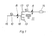
- FIG. 1 shows the arrangement of a self-switch cascade network with a main circuit breaker 10 and downstream circuit breakers 12 which are arranged between consumers 14 and a supply network 16 for protection against overload and short-circuit currents. It is provided that several consumers 14 are individually protected by circuit breakers 12 and several consumer networks 13 thus formed are brought together in a common branching point 18, which is connected to the supply network 16 via the main circuit breaker 10.
- FIG. 1 shows two possibilities for the occurrence of short-circuit currents, designated by the letters A and B.
- A short-circuit current
- B short-circuit currents
- a short circuit occurs in a consumer 14, which by a circuit breaker 12 is protected.
- the other consumer networks 13 are in normal operation, ie there is no short circuit.
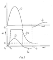
- FIG. 2 shows the time profile of a time control device used in the main circuit breaker 10 according to the invention with the corresponding current profiles.
- the abscissa serves as the time axis, while the corresponding energy level is plotted on the ordinate. For the applied currents, it is the current strength.
- I K represents the short-circuit current curve in the main current path and I K 'represents the damped short-circuit current curve in the secondary current path.
- I B shows the operating current curve.
- the time course of the time control device is identified by s (t).
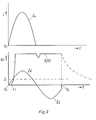
- FIG. 3 also shows the timing of the time control device here, however, for a short-circuit current I K that is to be present for a longer time.
- the designations of the other curve profiles shown correspond to those in FIG. 2.
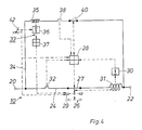
- the main circuit breaker 10 the circuit structure of which is shown in FIG. 4, has an input-side connection terminal 20 and an output-side connection terminal 22, which are connected to one another by a main current path 24.
- a main contact point 26 is arranged in this main current path 24.
- a main switching mechanism 28 is provided for actuating the main contact point 26 and can be acted upon by an electromagnetic quick release device 30 arranged in the main current path 24 behind the main contact point 26 in the energy flow direction.
- the solenoid 31 of the electromagnetic quick release is switched between the main contact point 26 and the outgoing connection terminal 22 in the main current path 24.
- an impact armature not shown here in the trigger coil 31 of the electromagnetic quick release 30, acts directly on the main contact point 26.
- an overcurrent release 32 is arranged in the main current path 24 between the access-side terminal 20 and the main contact point 26, which also cooperates with the main switching mechanism 28.
- a secondary current path 34 Connected to the connecting terminals 20, 22 is a secondary current path 34 which is electrically connected in parallel with the main current path 24 and in the line path of which a coil 35 of a timing control device 36, a second overcurrent release 38 and a further contact point 40 are arranged.
- the further contact point 40 is operatively connected to the main switching mechanism 28 and can be brought to the opening by the second overcurrent release 38, which also acts on the main switching mechanism 28.
- the main contact point 26 has a movable contact piece 27, which engages in a latching device 29 provided according to the invention when it is opened by the release coil 31 in a position between the closed and the open position.
- a detaching device 37 which belongs to the time control device 36 and is actuated by it, is coupled to the latching device 29.
- a manual control handle 42 is provided which is in operative connection with the main switching mechanism 28 and with the timing control device 36 and the latching device 29.
- the operating current I B flows from the connection terminal 20 on the access side, which is connected to the supply network 16, via the main current path 24 to the connection terminal 22 on the output side, to which the individual consumer networks 13 connect.
- the main contact point 26 is closed.
- a short-circuit current which, as indicated in FIG. 1, can be present both in a consumer 14 and also between the main circuit breaker and the common branching point 18 from which the consumer networks 13 are fed, the trigger coil 31 of the electromagnetic rapid release 30 is excited. whereby the main contact point 26 is opened immediately and the movable contact 27 engages in the latching device 29 during its opening movement.
- the main current path 24 is thus interrupted.
- the damped short-circuit current which is identified in FIGS. 2 and 3 by I K ', flows through the high-resistance shunt path 34, which is built up from the electrical series connection of the coil 35 designed as a voltage coil, the timing control element 36, the second overload release 38 and the contact point 40 is.
- the tripping behavior of the coil 35 of the timing control device 36 is characterized by the curve shape s (t) in FIGS. 2 and 3 as follows:
- a short-circuit current conducted as a result of a short circuit in the secondary current path 34 begins at t0 the first half-wave, which is striving for a maximum value.
- the current strength of the short-circuit current I K reaches a threshold value which is higher than the response current strength and which is required at least for exciting the coil 35 of the timing control device 36.
- the timer 36 is accordingly activated by excitation of the coil 35 and brought to a predetermined energy level with a steep increase. This energy level is maintained as long as the damped short-circuit current I K 'continues.
- a discharge process of the timing control device 36 is then initiated, which has an exponential course and is shown in the curve in FIG. 2 as a continuous falling line.
- the timing control device behaves in accordance with the course of the curve shown in FIG. 2, since the follow current I B in the secondary current path 34 is smaller than the response current strength, so that a new one
- the control device 36 is not actuated by the appropriately dimensioned coil 35.
- timing controller 36 time characteristic predetermined time t V applied to this with its attendant Entrast interests 37, which in turn triggers the latching device 29 on the main contact point 26th As a result, the movable contact piece 27 that is released in this way again reaches the closed position, so that the main contact point 26 is closed again and the normal operating state is restored.
- the second overcurrent release 38 which is arranged in the bypass flow path 34 and is designed as a thermobimetal, is suitable for this type of operation has, so that there is no unwanted triggering of the main switching mechanism 28 by the second overcurrent release 38.
- FIG. 3 shows the case in which the short-circuit current has not yet been switched off after the first half-wave. Therefore, the discharge process of the timing device is stopped with the second half-wave because the short-circuit current I K 'causes the timing device 36 to be reactivated by the coil 35, thus preventing its drop below the trigger level s for the unlatching device 37. Accordingly, the movable contact piece 27 of the main contact point 26 remains trapped in the latching device 29 and the main contact point 26 is opened.
- the second thermal bimetal 38 located in the secondary flow path 34 heats up.
- the second overcurrent release 38 responds and actuates the main switching mechanism 28, which then opens the further contact point 40 in the secondary current path 34 and further opens the movable contact piece 27 Main contact point 26 brought into the "off" position.
- the short-circuit current is finally switched off.
- the instantaneous switch-off must be ensured. This is ensured with the help of the electromagnetic quick release, which cooperates with the main switching mechanism 28.
- the main switching mechanism is acted upon by the electromagnetic quick release 30, the main contact point 26 and the second contact point 40 in the secondary current path and thus the main circuit breaker 10 are opened immediately.
- the movable contact piece 27 of the main contact point 26 is held in the latching device 29.
- the hand control handle 42 is actuated, the further contact point 40 in the bypass path 34 is initially closed, while the main contact point 26 remains open, so that there cannot be a current flow through the main contact point 26 at the first moment of switching on, but only a current flow via the bypass path comes about.
- the detent device 29 is also unlatched by the unlatching device 37. It is activated in accordance with the chronological course of the time control device 36 described above, which is acted upon directly by the manual control handle 42.
- the coil 35 activates the time control device 36, which initially maintains the energy level it has reached according to its characteristic. If the short-circuit current is subsequently switched off by a downstream circuit breaker, the movable contact piece 27 of the main contact point 26 is unlatched by the unlatching device 37, as previously described.
- the time control element 36 is activated again by the coil 35 and reaches the original energy level again, so that the main contact point 26 closes is omitted.
- the second overcurrent release 38 responds due to the heating due to the short-circuit current present and triggers the opening of the further contact point 40 in the secondary current path 34 via the main switching mechanism 28 and leads the further opening of the movable contact piece 27 of the main contact point 26 into the "off" position. Position.
Landscapes
- Emergency Protection Circuit Devices (AREA)
- Amplifiers (AREA)
Abstract
Description
Die Erfindung betrifft ein Verfahren sowie eine Einrichtung zur Durchführung des Verfahrens, zur selektiven Beherrschung von Kurzschlußströmen in elektrischen Verbrauchernetzen, die mittels Hauptsicherungsautomaten abgesichert sind und jeweils nachgeschaltete einzeln abgesicherte Verbraucher aufweisen.The invention relates to a method and a device for carrying out the method for the selective control of short-circuit currents in electrical consumer networks, which are protected by main circuit breakers and each have downstream individually protected consumers.
Diese Einrichtung ist ein selektiver Hauptsicherungsautomat, der zur selektiv gestaffelten Absicherung von einzeln abgesicherten Verbrauchern eines Verbrauchernetzes gegen Überströme in einem Verbraucherstromkreis selektiv gegenüber den übrigen Verbrauchern dient, und mit einem Hauptstrompfad sowie mit einem hierzu parallel geschalteten Nebenstrompfad, mit einer am Hauptstrompfad angeordneten Hauptkontaktstelle, die wenigstens ein festes und ein bewegliches Kontaktstück sowie eine zutge ordnete Lichtobogenlöscheinrichtung aufweist, mit einem ebenfalls im Hauptstrompfad angeordneten elektromagnetischen Schnellauslöser, der mit einem Hauptschaltwerk zusammenarbeitet, welches mit dem beweglichen Kontaktstück der Hauptkontaktstelle sowie mit einem Handschaltgriff und mit einem im Hauptstrompfad angeordneten Überstromauslöser in Wirkverbindung steht und das bewegliche Kontaktstück der Hauptkontaktstelle beaufschlagt, und mit je einer zugangsseitigen und einer abgangsseitigen Anschlußklemme ausgerüstet ist.This device is a selective main circuit breaker, which is used for the selectively staggered protection of individually secured consumers of a consumer network against overcurrents in a consumer circuit, selectively with respect to the other consumers, and with a main current path and with a secondary current path connected in parallel with it, with a main contact point arranged on the main current path at least one fixed and one movable contact piece as well as one has an ordered arc extinguishing device, with an electromagnetic quick release also arranged in the main current path, which works together with a main switching mechanism, which is in operative connection with the movable contact piece of the main contact point and with a manual control handle and with an overcurrent release arranged in the main current path and acts on the movable contact piece of the main contact point, and with one input-side and one output-side terminal is equipped.
Die vorgeordnete Absicherung von Verbrauchernetzen, welche einzeln abgesicherte Verbraucher aufweisen, wird heute immer noch durch Schmelzsicherungen (NH-Sicherungen) vorgesehen. Diese Art der Absicherung hat den Nachteil, daß bei Auftreten eines Kurzschlusses in einem Verbraucher bei nicht gegebener Selektivität durch Ansprechen der Hauptsicherung das gesamte Verbrauchernetz vom Versorgungsnetz getrennt wird, sowie ein Auswechseln der NH-Sicherung durch den Anwender nicht durchführbar ist.The upstream protection of consumer networks that have individually protected consumers is still provided today by fuses (NH fuses). This type of protection has the disadvantage that if a short-circuit occurs in a consumer with a lack of selectivity, the entire consumer network is disconnected from the supply network by responding to the main fuse, and the user cannot replace the NH fuse.
Zur Vermeidung dieses Nachteiles wurden selektive Hauptsicherungsautomaten entwickelt, welche wie die zuvor erwähnten Schmelzsicherungen den einzeln abgesicherten Verbrauchern, die in Verbrauchernetzen zusammengefaßt sein können, vorgeschaltet sind und bei Auftreten eines Kurzschlußstromes in einem der Verbraucher ansprechen und die Strombegrenzung des dem Verbraucher zugeordneten LS-Schalters unterstützen, jedoch nicht auslösen, falls der Kurzschluß von dem LS-Schalter selektiv abgeschaltet wird.To avoid this disadvantage, selective main circuit breakers have been developed which, like the fuses mentioned above, are connected upstream of the individually protected consumers, which can be combined in consumer networks, and respond when a short-circuit current occurs in one of the consumers and support the current limitation of the circuit breaker assigned to the consumer , but not trigger if the short circuit is selectively switched off by the circuit breaker.
Ein derartiger selektiver Hauptsicherungsautomat ist aus der DE-PS 28 54 616 bekanntgeworden, bei dem der Kurzschlußstrom in einen hochohmigen Nebenstrompfad geführt wird, der sich parallel zu einem der beiden Haaptkontakte befindet, welche nach Überschreitung eines bestimmten Stromes von einer vom Kurzschlußstrom durchflossenen Spule aufgeschlagen werden.Such a selective main circuit breaker has become known from DE-PS 28 54 616, in which the short-circuit current is led into a high-resistance bypass current path which is parallel to one of the two Haaptkontakte which are opened after a certain current is exceeded by a coil through which the short-circuit current flows .
Hat ein nachgeschalteter Leitungsschutzschalter den Kurzschlußstrom nicht abgeschaltet, so fließt der Kurzschlußstrom weiter. Wenn die Öffnungskraft der Schlagspule des elektromagnetischen Schnellauslösers im Bereich des Nulldurchgangs unter die Kontaktschließkräfte absinkt, erfolgt ein Wiederschließen der Kontakte, so daß ein weiteres Öffnen erst nach Überschreiten des Ansprechwertes der Schlagspule während der nächsten Halbwelle stattfinden kann.If a downstream circuit breaker has not switched off the short-circuit current, the short-circuit current continues to flow. If the opening force of the impact coil of the electromagnetic quick release falls below the contact closing forces in the area of the zero crossing, the contacts close again, so that further opening can only take place after the response value of the impact coil has been exceeded during the next half-wave.
Im Nebenstrompfad befindet sich ein empfindliches Thermobimetall, welches durch diesen iterativ wirksamen Kurzschlußstrom aufgeheizt wird und schließlich die endgültige Kontaktöffnung herbeiführt.In the bypass current path there is a sensitive thermobimetal which is heated up by this iteratively effective short-circuit current and finally brings about the final contact opening.
Obwohl mit Hilfe dieses selektiv wirksamen Hauptsicherungsautomaten die Nachteile der vorher üblichen Schmelzsicherungen vermieden werden, führt das mehrmalige Öffnen und Schließen der Hauptkontakte während einer Kurzschlußstromabschaltung in einem bestimmten Kurzschlußstrombereich zu höheren Durchlaß-I²t-Werten.Although the disadvantages of the previously conventional fuses are avoided with the aid of this selectively effective main circuit breaker, the repeated opening and closing of the main contacts during a short-circuit current shutdown leads to higher forward I²t values in a certain short-circuit current range.
Ausgehend vom vorstehend geschilderten Stand der Technik ist es Aufgabe der Erfindung ein Verfahren sowie einen möglichst raumsparend gestalteten Hauptsicherungsautomaten zur Durchführung des Verfahrens anzugeben, mit dem die Nachteile im Stande der Technik, vermieden werden.Starting from the prior art described above, it is an object of the invention to provide a method and a main circuit breaker designed to be as space-saving as possible for carrying out the method, with which the disadvantages in the prior art are avoided.
Die Schutzeinrichtung, mit welchem die Aufgabe gelöst wird, ist erfindungsgemäß dadurch gekennzeichnet, daß bei Auftreten eines Kurzschlußstromes, der in einem dem Hauptsicherungsautomaten nachgeschalteten Verbrauchernetz verursacht ist, selbsttätig der Hauptstrompfad im Hauptsicherungsautomaten unterbrochen und der Kurzschlußstrom über einen hierzu parallel geschalteten relativ hochohmigen Nebenstrompfad geleitet wird, daß hierauf eine Selektivitätseinrichtung erregt wird, die nach einer vorgebbaren Zeit, während der der Kurzschlußstrom in betroffenen Verbrauchernetz vom zugeordneten LS-Schalter abgeschaltet ist, den Hauptstrompfad wieder schließt, daß aber bei weiterhin anstehendem Kurzschluß die endgültige Unterbrechung des Hauptstrompfades sowie die Unterbrechung des Nebenstrompfades bewirkt wird und daß zur Wiedereinschaltung des Hauptsicherungsautomaten dieser manuell betätigt werden muß.The protective device with which the object is achieved is characterized according to the invention in that when a short-circuit current occurs, which is caused in a consumer network connected downstream of the main circuit breaker, the main current path in the main circuit breaker is automatically interrupted and the short-circuit current is conducted via a relatively high-resistance secondary current path connected in parallel with this that thereupon a selectivity device is energized, which closes the main current path again after a predefinable time during which the short-circuit current in the affected consumer network is switched off by the associated circuit breaker, but that if the short circuit continues, the final interruption of the main current path and the interruption of the secondary current path is effected and that the main circuit breaker must be manually operated to restart it.
Zur Durchführung des vorstehend gekennzeichneten Verfahrens ist ein selektiver Hauptsicherungsautomat entsprechend der eingangs genannten Art vorgesehen, der erfindungsgemäß dadurch gekennzeichnet ist, daß eine Rastvorrichtung vorgesehen ist, in der das infolge Kurzschlußstrom aufgeschlagene bewegliche Kontakstück der Hauptkontaktstelle einrastet, daß der Nebenstrompfad, der an den Anschlußklemmen mit dem Hauptstrompfad verbunden ist, eine Selektivitätseinrichtung aufweist, die mit der Rastvorrichtung zusammenarbeitet, daß die durch einen Kurzschlußstrom ausgelöste Selektivitätseinrichtung zeitgesteuert die Entrastung des beweglichen Kontaktstückes hervorruft und daß zur sicheren Abschaltung eines länger anstehenden Kurzschlußstromes ein mit der Selektivitätseinrichtung elektrisch in Reihe geschalteter zweiter Überstromauslöser im Nebenstrompfad angeord net ist, der mit dem Hauptschaltwerk zusammenarbeitet und bei Auslösung durch einen anstehenden Kurzschlußstrom die Öffnung einer weiteren im Nebenstrompfad angeordneten Kontaktstelle auslöst, wodurch das Verbrauchernetz vom Versorgungsnetz getrennt ist.To carry out the above-identified method, a selective main circuit breaker of the type mentioned at the outset is provided, which is characterized according to the invention in that a latching device is provided in which the movable contact piece of the main contact point which is opened as a result of short-circuit current snaps in, that the secondary current path connected to the connecting terminals is connected to the main current path, has a selectivity device which cooperates with the latching device, that the selectivity device triggered by a short-circuit current triggers the unlatching of the movable contact piece in a time-controlled manner and that a second overcurrent release in the secondary current path, which is connected in series with the selectivity device, for the safe disconnection of a longer-standing short-circuit current arranged net, which cooperates with the main switchgear and, when triggered by an existing short-circuit current, triggers the opening of a further contact point arranged in the secondary current path, as a result of which the consumer network is separated from the supply network.
Als weiterhin anstehender Kurzschlußstrom wird hierbei ein solcher Kurzschlußstrom verstanden, der während der ersten Halbwelle mit seinem Auftreten noch nicht abgeschaltet ist, z. B. im 50 Hz-Netz 10 ms.A short-circuit current which is still present is understood to be such a short-circuit current which has not yet been switched off during the first half-wave when it occurs, for. B. in the 50
In vorteilhafter Ausgestaltung der Erfindung ist vorgesehen, daß die Selektivitätseinrichtung aus einer im Nebenstrompfad eingeschalteten Spule gebildet ist, deren Anker eine Zeitsteuereinrichtung beaufschlagt, die ihrerseits mit einer Entrastungseinrichtung zusammenarbeitet, mittels der die Verrastung des beweglichen Kontaktstückes der Hauptkontaktstelle lösbar ist.In an advantageous embodiment of the invention it is provided that the selectivity device is formed from a coil switched on in the secondary current path, the armature of which acts on a timing control device which in turn cooperates with an unlatching device by means of which the locking of the movable contact piece of the main contact point can be released.
Die Spule der Selektivitätseinrichtung ist dabei als Spannungspule gestaltet, d. h. ihre Windungszahl ist so festgelegt, daß sie ähnlich einer Drosselspule einen hohen Widerstand bildet und erst bei einer Stromstärke, die oberhalb der Nennstromstärke liegt, für die der Hauptsicherungsautomat ausgelegt ist, erregt wird.The coil of the selectivity device is designed as a voltage coil, i. H. its number of turns is determined so that it forms a high resistance similar to a choke coil and is only energized at a current which is above the nominal current for which the main circuit breaker is designed.
Gemäß einem weiteren vorteilhaften Merkmal der Erfindung ist vorgesehen, daß der zweite, im Nebenstrompfad angeordnete kurzzeitverzögerter Überstromauslöser, der mit der Spule der Selektivitätseinrichtung elektrisch in Reihe geschaltet ist, als Bimetall ausgebildet ist.According to a further advantageous feature of the invention, it is provided that the second short-time delayed overcurrent release, which is arranged in the bypass path and is electrically connected in series with the coil of the selectivity device, is designed as a bimetal.
Hierdurch wird in vorteilhafter Weise erreicht, daß die für den wegen der geöffneten Hauptkontaktstelle vom Hauptstrompfad in den Nebenstrompfad geleiteten Kurzschlußstrom als Vorwiderstand wirkende Spule der Selektivitätseinrichtung einen Spannungsabfall bewirkt, so daß der Überstromauslöser mit einem verringerten Kurzschlußstrom belastet ist. Je nach gewünschter Selektivität kann der Überstromauslöser durch entsprechende Dimensionierung seiner Abmessungen sowie durch entsprechende Werkstoffwahl ausgelegt werden.It is hereby advantageously achieved that the coil of the selectivity device acting as a series resistor for the short-circuit current acting as a series resistor for the short-circuit current which is conducted from the main current path into the secondary current path because of the open main contact point, so that the overcurrent release is loaded with a reduced short-circuit current. Depending on the desired selectivity, the overcurrent release can be designed by appropriate dimensioning of its dimensions and by appropriate choice of materials.
Gemäß einem weiteren Merkmal der Erfindung besitzt der Nebenstrompfad eine weitere Kontaktstelle, über welche bei geöffnetem Hauptkontakt der gesamte Reststrom zum Verbrauchernetz fließt.According to a further feature of the invention, the secondary current path has a further contact point via which the entire residual current flows to the consumer network when the main contact is open.
Im Falle, daß der Leitungsschutzschalter des nachgeschalteten, kurzschlußführenden Verbrauchers nicht oder nicht rechtzeitig anspricht, erfolgt durch den weiteren Überstromauslöser im Nebenstrompfad die Auslösung des Hauptschaltwerkes, mit dem er in Wirkverbindung steht. Hierbei wird die weitere im Nebenstrompfad befindliche Kontaktstelle vom Hauptschaltwerk geöffnet, sowie die im Hauptstrompfad befindliche Hauptkontaktstelle in die endgültige "Aus"-Stellung gebracht, so daß es zur Trennung des Verbrauchernetzes vom Versorgungsnetzes kommt und der Kurzschlußstrom endgültig abgeschaltet ist.In the event that the circuit breaker of the downstream, short-circuiting consumer does not respond or does not respond in time, the further overcurrent release in the bypass circuit triggers the main switching mechanism with which it is in operative connection. Here, the further contact point located in the secondary current path is opened by the main switching mechanism, and the main contact point located in the main current path is brought into the final “off” position, so that the consumer network is disconnected from the supply network and the short-circuit current is finally switched off.
In Übereinstimmung mit bestehenden Vorschriften ist dabei vorgesehen, daß diese endgültige Trennung des Verbrauchernetzes vom Versorgungsnetz nur durch manuellen Eingriff, d. h. durch Betätigung des am Hauptsicherungsautomaten befindlichen Handschaltgriffes, aufgehoben werden kann.In accordance with existing regulations, it is provided that this final separation of the consumer network from the supply network can only be eliminated by manual intervention, ie by actuating the manual control handle located on the main circuit breaker.
Gemäß einer weiteren vorteilhaften Ausgestaltung der Erfindung ist vorgesehen, daß der erwähnte Handschaltgriff, der mit dem Hauptschaltwerk zusammenarbeitet, auch mit der Zeitverzögerungseinrichtung der Selektivitätseinrichtung gekoppelt ist.According to a further advantageous embodiment of the invention, it is provided that the aforementioned manual control handle, which cooperates with the main switching mechanism, is also coupled to the time delay device of the selectivity device.
Erfindungsgemäß ist die Rastvorrichtung als mechanische Fangvorrichtung für die beweglichen Teile der Hauptkontakstelle ausgestaltet, welche die Kontakte in mindestens einer Position zwischen der "Ein"- und "Aus"-Stellung festhält.According to the invention, the latching device is designed as a mechanical catching device for the moving parts of the main contact point, which holds the contacts in at least one position between the "on" and "off" position.
Die "Aus"-Stellung des beweglichen Kontaktstückes der Hauptkontaktstelle wird nach der erfindungsgemäßen Ausgestaltung sowohl durch die Auslösung des Schalters aufgrund eines Kurzschlusses als auch mit Hilfe des Handschaltgriffes erreicht.The "off" position of the movable contact piece of the main contact point is achieved according to the embodiment of the invention both by triggering the switch due to a short circuit and with the help of the manual control handle.
Die Zeitverzögerungseinrichtung der Selektivitätseinrichtung besitzt eine Energie/Zeit-Charakteristik entsprechend dem in Figur 2 gezeigten Kurvenverlauf s(t). Dabei ist vorgesehen, daß entsprechend der hochohmigen Auslegung der Erregerspule der Selektivitätseinrichtung diese erst bei Erreichen eines Stromwertes ausgelöst wird, der oberhalb der Nennstromstärke liegt. Mit der Auslösung der Zeitverzögerungseinrichtung durch den Anker der Erregerspule der Selektivitätseinrichtung erfolgt ein Speichervorgang mit sehr steilem Anstieg auf ein festgelegtes Niveau, welches eine halbe Periode lang entsprechend der Dauer einer Halbwelle, gehalten wird. Danach folgt eine Entladung mit exponentiellem zeitlichem Verlauf.The time delay device of the selectivity device has an energy / time characteristic corresponding to the curve shape s (t) shown in FIG. It is provided that, according to the high-resistance design of the excitation coil of the selectivity device, this is only triggered when a current value is reached which is above the nominal current. When the time delay device is triggered by the armature of the excitation coil of the selectivity device, a storage process takes place with a very steep rise to a fixed level, which is held for half a period corresponding to the duration of a half-wave. This is followed by an exponential discharge.
Dieses Verhalten gilt dann, wenn der Kurzschlußstrom innerhalb der ersten Halbwelle abgeschaltet wird. Nach einer vorgegebenen Zeit tE entsprechend dem zeitlichen Verlauf der Abklingkurve der Zeitsteurereinrichtung betätigt diese eine mit ihr gekoppelte Entrastungseinrichtung, wodurch die Entrastung der in der Rastvorrichtung gehaltenen beweglichen Kontaktstücke der Hauptkontaktstelle ausgelöst wird, so daß diese wieder schließen und der normale Betriebszustand wieder hergestellt ist.This behavior applies if the short-circuit current is switched off within the first half-wave. After a predetermined time t E in accordance with the time course of the decay curve of the time control device, this actuates a detaching device coupled to it, whereby the detaching of the movable contact pieces held in the latching device is triggered so that the main contact point closes again and the normal operating state is restored.
Ist der Kurzschluß nach der ersten Halbwelle noch nicht abgeschaltet, so erfolgt eine erneute Aktivierung der Zeitsteuereinrichtung während der zweiten Halbwelle. Dies verhindert das Absinken ihrer Kennlinie unter das Auslöseniveau und damit das Schließen der Hauptkontaktstelle (Figur 3).If the short circuit has not yet been switched off after the first half-wave, the time control device is reactivated during the second half-wave. This prevents their characteristic curve from dropping below the tripping level and thus closing the main contact point (FIG. 3).
Einhergehend mit dem zuvor beschriebenen Vorgängen in der Selektivitätseinrichtung wird der im Nebenstrompfad befindliche zweite Überstromauslöser, der vorteilhafterweise als Thermobimetall ausgeführt ist, durch Joulesche Wärme aufgeheizt.Along with the above-described processes in the selectivity device, the second overcurrent release located in the bypass path, which is advantageously designed as a thermobimetal, is heated by Joule heat.
Als Auslegungsbedingung für dieses Thermobimetall im Hinblick auf den Betriebsfall gilt
In weiterer vorteilhafter Ausgestaltung der Erfindung ist vorgesehen, daß, insbesondere um eine gefahrlose Bedienung des Schalters beim Einschalten auf einen Kurzschlußstrom zu gewährleisten, die Hauptkontakte, wie bereits erwähnt, auch beim manuellen Einschalten von der Rastvorrichtung in einer Zwischenstellung gehalten werden und gleichzeitig der Trennkontakt im Nebenstrompfad geschlossen wird, so daß im ersten Augenblick nach dem Einschalten ein Stromfluß nur über den Nebenstrompfad nicht aber über die Hauptkontaktstelle möglich ist.In a further advantageous embodiment of the invention it is provided that, in particular in order to ensure safe operation of the switch when switching on a short-circuit current, the main contacts, as already mentioned, are kept in an intermediate position by the latching device even when switched on manually, and at the same time the isolating contact in Secondary current path is closed, so that in the first moment after switching on a current flow is only possible via the secondary current path and not via the main contact point.
Für den Fall, ein daß Kurzschlußstrom einen vorgegebenen Wert übersteigt, der dem des selektiven Grenzkurzschlußstromes entspricht, soll gemäß der Erfindung die Auslösung unverzögert erfolgen. Hierzu dient der elektromagnetische Schnellauslöser, der im Hauptstrompfad zwischen der Hauptkontaktstelle und der abgangseitigen Anschlußklemme angeordnet ist und dessen Anker, der als Klappanker an die Schlagspule des Schnellauslösers angegliedert ist und bei Überschreitung des kritischen Kurzschlußstromes auf das Hauptschaltwerk einwirkt, welches die Hauptkontaktstelle sowie auch die weitere Kontaktstelle im Nebenstrompfad öffnet, wodurch die endgültige Abschaltung des Kurzschlußstromes sofort erfolgt.In the event that a short-circuit current exceeds a predetermined value which corresponds to that of the selective limit short-circuit current, the triggering should take place without delay according to the invention. For this purpose, the electromagnetic quick release, which is arranged in the main current path between the main contact point and the outgoing connection terminal and its armature, which is attached as a hinged armature to the impact coil of the quick release and acts on the main switching mechanism when the critical short-circuit current is exceeded, which acts on the main contact point as well as the others Contact point in the secondary current path opens, which means that the short-circuit current is switched off immediately.
Diese und weitere vorteilhafte Ausgestaltungen sind in den Unteransprüchen angegeben.These and other advantageous configurations are specified in the subclaims.
Anhand eines in der Zeichnung dargestellten Ausführungsbeispieles sollen die Erfindung, vorteilhafte Ausgestaltungen und besondere Vorteile der Erfindung näher erläutert und beschrieben werden.The invention, advantageous refinements and particular advantages of the invention are to be explained and described in more detail with reference to an exemplary embodiment shown in the drawing.
Es zeigen:
Figur 1 Die Anordnung eines Selbstschalterkaskadennetzes,- Figur 2 ein Diagramm der zeitlichen Verläufe der Ströme in Haupt- bzw. Nebenstrompfad sowie der Zeitsteuereinrichtung bei einem Kurzschluß, der von einem LS-Schalter abgeschaltet wird,
- Figur 3 das Diagramm der zeitlichen Verläufe der Ströme im Haupt- bzw. Nebenstrompfad sowie der Zeitsteuereinrichtung bei länger anstehendem Kurzschluß und dessen Abschaltung,
- Figur 4 Prinzipschaltbild des erfindungsgemäßen Hauptsicherungsautomaten.
- 1 shows the arrangement of a self-switch cascade network,
- FIG. 2 shows a diagram of the time profiles of the currents in the main or secondary current path and of the time control device in the event of a short circuit that is switched off by a circuit breaker,
- FIG. 3 shows the diagram of the time profiles of the currents in the main or secondary current path and the time control device in the event of a long-term short circuit and its disconnection,
- Figure 4 Schematic diagram of the main circuit breaker according to the invention.
In Figur 1 ist die Anordnung eines Selbstschalterkaskadennetzes mit einem Hauptsicherungsautomaten 10 sowie nachgeschalteten Leitungsschutzschaltern 12 gezeigt, welche zum Schutz gegen Überlast- und Kurzschlußströme zwischen Verbrauchern 14 und einem Versorgungsnetz 16 angeordnet sind. Dabei ist vorgesehen, daß mehrere Verbraucher 14 jeweils einzeln durch Leitungsschutzschalter 12 abgesichert sind und mehrere so gebildete Verbrauchernetze 13 in einem gemeinsamen Verzweigungspunkt 18 zusammengeführt sind, der über den Hauptsicherungsautomaten 10 mit dem Versorgungsnetz 16 verbunden ist.FIG. 1 shows the arrangement of a self-switch cascade network with a
In der in Figur 1 gezeigten Darstellung sind zwei mit den Buchstaben A und B bezeichnete Möglichkeiten für das Auftreten von Kurzschlußströmen dargestellt. Im ersten Fall, der mit dem Buchstaben A gekennzeichnet ist, tritt ein Kurzschluß in einem Verbraucher 14 auf, der durch einen Leitungsschutzschalter 12 abgesichert ist. Die übrigen Verbrauchernetze 13 befinden sich hierbei im Normalbetrieb, d. h., dort ist kein Kurzschluß.The illustration shown in FIG. 1 shows two possibilities for the occurrence of short-circuit currents, designated by the letters A and B. In the first case, which is marked with the letter A, a short circuit occurs in a
Im zweiten Fall tritt ein Kurzschluß zwischen dem Verzweigungspunkt 18 und dem Hauptsicherungsautomaten 10 auf, der daraufhin anspricht und das gesamte Kaskadennetz 11 mit den Verbrauchern 14 vom Versorgungsnetz 16 trennt.In the second case, a short circuit occurs between the
Unter Umständen ist es möglich, daß bei Auftreten eines Kurzschlußfalles A der zugeordnete Leitungsschutzschalter 12 nur verzögert anspricht, so daß der Hauptsicherungsautomat 10 anspricht und so, wie zuvor für den Kurzschlußfall B beschrieben, das gesamte Kaskadennetz 11 mit den Verbrauchern 14 vom Versorgungsnetz 16 abtrennt.Under certain circumstances, it is possible that when a short-circuit case A occurs, the
In Figur 2 ist der zeitliche Verlauf einer im erfindungsgemäßen Hauptsicherungsautomaten 10 verwendeten Zeitsteuereinrichtung mit den entsprechenden Stromverläufen darstellt. Die Abszisse dient als Zeitachse, während auf der Ordinate das entsprechende Energieniveau aufgetragen ist. Für die aufgetragenen Ströme ist es die Stromstärke.FIG. 2 shows the time profile of a time control device used in the
Mit IK ist der Kurzschlußstromverlauf im Hauptstrompfad und mit IK′ der gedämpfte Kurzschlußstromverlauf im Nebenstrompfad dargestellt. IB zeigt den Betriebsstromverlauf. Mit s(t) ist der zeitliche Verlauf der Zeitsteuereinrichtung gekennzeichnet.I K represents the short-circuit current curve in the main current path and I K 'represents the damped short-circuit current curve in the secondary current path. I B shows the operating current curve. The time course of the time control device is identified by s (t).
In figur 3 ist ebenfalls der zeitliche Verlauf der Zeitsteuereinrichtung hier jedoch für einen länger anstehenden Kurzschlußstrom IK dargstellt. Die Bezeichnungen der weiteren dargstellten Kurvenverläufe entspricht der in der Figur 2.FIG. 3 also shows the timing of the time control device here, however, for a short-circuit current I K that is to be present for a longer time. The designations of the other curve profiles shown correspond to those in FIG. 2.
Bevor auf die Kurvendarstellung näher eingegangen werden soll, ist es zweckmäßig, den prinzipiellen Schaltungsaufbau des erfindungsgemäßen Hauptsicherungsautomaten 10 zu erläutern. Dieser Schaltungsaufbau ist in Figur 4 gezeigt.Before the curve display is to be discussed in more detail, it is expedient to explain the basic circuit structure of the
Der Hauptsicherungsautomat 10, dessen Schaltungsaufbau in Figur 4 gezeigt ist, besitzt eine zugangsseitige Anschlußklemme 20 und eine abgangsseitige Anschlußklemme 22, welche von einem Hauptstrompfad 24 miteinander verbunden sind. In diesem Hauptstrompfad 24 ist eine Hauptkontaktstelle 26 angeordnet. Zur Betätigung der Hauptkontaktstelle 26 ist ein Hauptschaltwerk 28 vorgesehen, das von einem in Energieflußrichtung hinter der Hauptkontaktstelle 26 im Hauptstrompfad 24 angeordneten elektromagnetischen Schnellauslöser 30 beaufschlagbar ist. Die Magnetspule 31 des elektromagnetischen Schnellauslösers ist dabei zwischen der Hauptkontaktstelle 26 und der abgangseitigen Anschlußklemme 22 in den Hauptstrompfad 24 eingeschaltet.The
In besonderer Ausgestaltung der Erfindung ist vorgesehen, daß ein hier nicht näher gezeigter in der Auslösespule 31 des elektromagnetischen Schnellauslösers 30 geführter Schlaganker unmittelbar auf die Hauptkontaktstelle 26 einwirkt.In a special embodiment of the invention it is provided that an impact armature, not shown here in the
Außerdem ist in den Hauptstrompfad 24 zwischen der zugangsseitigen Anschlußklemme 20 und der Hauptkontaktstelle 26 ein Überstromauslöser 32 angeordnet, der ebenfalls mit dem Hauptschaltwerk 28 zusammenarbeitet.In addition, an overcurrent release 32 is arranged in the main
An den Anschlußklemmen 20, 22 ist ein zum Hauptstrompfad 24 elektrisch parallel geschalteter Nebenstrompfad 34 angeschlossen, in dessen Leitungsweg eine Spule 35 einer Zeitsteuerungseinrichtung 36, ein zweiter Überstromauslöser 38 sowie eine weitere Kontaktstelle 40 angeordnet sind.Connected to the connecting
Die weitere Kontaktstelle 40 steht in Wirkverbindung mit dem Hauptschaltwerk 28 und kann von dem zweiten Überstromauslöser 38, die ebenfalls das Hauptschaltwerk 28 beaufschlagt, zur Öffnung gebracht werden.The
Die Hauptkontaktstelle 26 besitzt ein bewegliches Kontaktstück 27, welches in einer erfindungsgemäß vorgesehenen Rastvorrichtung 29 beim Öffnen durch die Auslösespule 31 in einer Position zwischen der Schließ- und der Offenstellung einrastet.The
Mit der Rastvorrichtung 29 gekoppelt ist eine Entrastungseinrichtung 37, die zur Zeitsteurereinrichtung 36 gehört und von dieser betätigt wird.A detaching
Um auch die manuelle Betätigung des erfindungsgemäßen Hauptsicherungsautomaten 10 sicherzustellen, ist ein Handschaltgriff 42 vorgesehen, der in Wirkverbindung mit dem Hauptschaltwerk 28 sowie mit der Zeitsteuereinrichtung 36 und der Rastvorrichtung 29 steht.In order to also ensure the manual actuation of the
Nun soll die Funktion des Hauptsicherungsautomaten 10 unter Bezugnahme auf die Figuren 2 bzw. 3 sowie 4 erläutert werden.The function of the
Im Nennbetrieb fließt der Betriebsstrom IB von der zugangsseitigen Anschlußklemme 20, die mit dem Versorgungsnetz 16 verbunden ist, über dem Hauptstrompfad 24 zur abgangsseitigen Anschlußklemme 22, an welche die einzelnen Verbrauchernetze 13 anschließen. Hierbei ist die Hauptkontaktstelle 26 geschlossen. Bei Auftreten eines Kurzschlußstromes, der, wie in Figur 1 angedeutet, sowohl in einem Verbraucher 14 als auch zwischen dem Hauptsicherungsautomaten und dem gemeinsamen Verzweigungspunkt 18, von dem die Verbrauchernetze 13 gespeist werden, vorliegen kann, wird die Auslösespule 31 des elektromagnetischen Schnellauslösers 30 erregt, wodurch unmittelbar die Hauptkontaktstelle 26 geöffnet wird und das bewegliche Kontaktsück 27 bei seiner Öffnungsbewegung in der Rastvorrichtung 29 einrastet. Damit ist der Hauptstrompfad 24 unterbrochen.In rated operation, the operating current I B flows from the
Der gedämpfte Kurzschlußstrom, der in den Figuren 2 und 3 mit IK′ gekennzeichnet ist, fließt durch den hochohmigen Nebenstrompfad 34, der aus der elektrischen Reihenschaltung der als Spannungsspule ausgelegten Spule 35, des Zeitsteuerungsgliedes 36, des zweiten Überlastauslösers 38 sowie der Kontaktstelle 40 aufgebaut ist.The damped short-circuit current, which is identified in FIGS. 2 and 3 by I K ', flows through the high-
Das Auslöseverhalten der Spule 35 der Zeitsteuereinrichtung 36 ist durch den Kurvenverlauf s (t) in den Figuren 2 und 3 wie folgt gekennzeichnet:The tripping behavior of the
Ein infolge Kurzschluß in den Nebenstrompfad 34 geleiteter Kurzschlußstrom beginnt bei t₀ die erste Halbwelle, die einem Maximalwert zustrebt. Bei t₁ erreicht die Stromstärke des Kurzschlußstromes IK einen Schwellwert der höher liegt als Ansprechstromstärke die und wenigstens zur Erregung der Spule 35 der Zeitsteuereinrichtung 36 erforderlich ist. Bei t₁ wird demgemäß durch Erregung der Spule 35 die Zeitsteuereinrichtung 36 aktiviert und mit steilem Anstieg auf ein vorgegebenes Energieniveau gebracht. Dieses Energieniveau wird gehalten, solange der gedämpfte Kurzschlußstrom IK′ andauert. Danach wird ein Entladungsvorgang der Zeitsteuereinrichtung 36 eingeleitet, der einen exponentiellen Verlauf hat und in der Kurvendarstellung in Figur 2 als durchgezogene abfallende Linie dargestellt ist.A short-circuit current conducted as a result of a short circuit in the secondary
Wenn der Kurzschlußstrom innerhalb der ersten Halbwelle durch den dem Hauptsicherungsautomaten nachgeschalteten Leitungsschutzschalter des kurzschlußführenden Verbrauchernetzes 13 abgeschaltet ist, so verhält sich die Zeitsteuereinrichtung gemäß dem in Figur 2 dargestellten Kurvenverlauf, da der Folgestrom IB im Nebenstrompfad 34 kleiner der Ansprechstromstärke ist, so daß eine erneute Betätigung der Zeitsteuereinrichtung 36 durch die entsprechend dimensionierte Spule 35 nicht erfolgt. Nach einer für die Zeitsteuereinrichtung 36 charakteristischen Zeitkennlinie vorgegebenen Zeit tV beaufschlagt diese die mit ihr verbundene Entrasteinrichtung 37, welche ihrerseits die Rastvorrichtung 29 an der Hauptkontaktstelle 26 auslöst. Das aur diese Weise freigewordene bewegliche Kontaktstück 27 erreicht dadurch wieder die Schließstellung, so daß die Hauptkontaktstelle 26 wieder geschlossen und der normale Betriebszustand wieder hergestellt ist.If the short-circuit current within the first half-wave is switched off by the circuit breaker of the short-
In diesem Zusammenhang ist darauf hinzuweisen, daß der im Nebenstrompfad 34 angeordnete zweite Überstromauslöser 38, der als Thermobimetall ausgebildet ist, für diesen Betriebsfall ein
In Figur 3 ist der Fall dargestellt, daß der Kurzschlußstrom nach der ersten Halbwelle noch nicht abgeschaltet ist. Daher wird mit der zweiten Halbwelle der Entladevorgang der Zeitsteuereinrichtung gestoppt, weil durch den anstehenden Kurzschlußstrom IK′ die Zeitsteuereinrichtung 36 von der Spule 35 erneut aktiviert wird und so deren Abfall unter das Auslöseniveau s für die Entrasteinrichtung 37 verhindert. Demgemäß bleibt das bewegliche Kontaktstück 27 der Hauptkontaktstelle 26 in der Rastvorrichtung 29 gefangen, und die Hauptkontaktstelle 26 geöffnet.FIG. 3 shows the case in which the short-circuit current has not yet been switched off after the first half-wave. Therefore, the discharge process of the timing device is stopped with the second half-wave because the short-circuit current I K 'causes the
Gleichzeitig kommt es zur Aufheizung des im Nebenstrompfad 34 befindlichen zweiten Thermobimetalls 38. Nach Erreichen seines Auslöseintegrals spricht der zweite Überstromauslöser 38 an und betätigt das Hauptschaltwerk 28, welches daraufhin die Öffnung der weiteren Kontaktstelle 40 im Nebenstrompfad 34 sowie die weitere Öffnung des beweglichen Kontaktstückes 27 der Hauptkontaktstelle 26 bis in die "Aus"-Stellung herbeiführt. Hierdurch ist der Kurzschlußstrom endgültig abgeschaltet.At the same time, the second thermal bimetal 38 located in the
Für den Fall, daß der Kurzschlußstrom einen vorgegebenen Wert übersteigt, muß die unverzögerte Ausschaltung sichergestellt sein. Dies wird mit Hilfe des elektromagnetischen Schnellauslösers gewährleistet, der mit dem Hauptschaltwerk 28 zusammenarbeitet. Bei Beaufschlagung des Hauptschaltwerkes durch den elektromagnetischen Schnellauslöser 30 erfolgt umgehend die Öffnung der Hauptkontaktstelle 26 sowie der zweiten Kontaktstelle 40 im Nebenstrompfad und somit des Hauptsicherungsautomaten 10.In the event that the short-circuit current exceeds a predetermined value, the instantaneous switch-off must be ensured. This is ensured with the help of the electromagnetic quick release, which cooperates with the
Um beim manuellen Einschalten des Hauptsicherungsautomaten bei beliebigen Kurzschlußströmen dem betriebsmäßigen Abschalten des Gerätes von Kurzschlußströmen zu entsprechen, ist das bewegliche Kontaktstück 27 der Hauptkontakstelle 26, wie bereits erwähnt, in der Rastvorrichtung 29 gehalten. Bei Betätigung des Handschaltgriffes 42 wird zunächst die weitere Kontaktstelle 40 im Nebenstrompfad 34 geschlossen, während die Hauptkontaktstelle 26 weiterhin geöffnet bleibt, so daß es nicht zu einem Stromfluß über die Hauptkontaktstelle 26 im ersten Augenblick des Einschaltens kommen kann, sondern nur über den Nebenstrompfad ein Stromfluß zustande kommt.In order to correspond to the operational switching off of the device from short-circuit currents when the main circuit breaker is switched on manually in the event of any short-circuit currents, the
Beim Einschalten sind drei unterschiedliche Betriebsfälle zu berücksichtigen. Hierbei ist davon auszugehen, daß die beiden Kontaktstellen 26, 40 jeweils geöffnet sind.Three different operating cases must be taken into account when switching on. It can be assumed here that the two
Soll der Hauptsicherungsautomat 10 auf Nennbetrieb eingeschaltet werden, d. h. mit eingeschalteten Verbrauchern 14, erfolgt die Entrastung der Rastvorrichtung 29 ebenfalls durch die Entrasteinrichtung 37. Ihre Aktivierung erfolgt entsprechend dem vorstehend beschriebenen zeitlichen Verlauf der Zeitsteuereinrichtung 36, die unmittelbar von dem Handschaltgriff 42 beaufschlagt wird.If the
Beim Einschalten des Hauptsicherungsautomaten 10 auf Leerlauf, d. h. bei abgeschaltetem Verbrauchern 14, ist ebenfalls die manuelle Aktivierung der Zeitsteuereinrichtung 36 durch Betätigung des Handschaltgriffes 42 vorgesehen, wobei hier ebenso wie beim Einschalten auf Last zunächst der Nebenstrompfad 34 eingeschaltet und dann mit entsprechender zeitlicher Verzögerung die Schließung des Hauptstrompfades 24 freigegeben ist.When the
Entsprechend dem zuvor beschriebenen Einschaltverlauf beim manuellen Einschalten des Hauptsicherungsautomaten ist ersichtlich, daß ein Stromfluß zunächst nur im Nebenstrompfad 34 zustande kommt, d. h., der Hauptstrompfad 24 ist aufgrund der geöffneten Hauptkontaktstelle 26 unterbrochen. Der weitere Verlauf des Einschaltvorganges entspricht dem bei der Kurzschlußstromabschaltung.According to the switch-on process described above when the main circuit breaker is switched on manually, it can be seen that a current flow initially occurs only in the secondary
Die Spule 35 aktiviert die Zeitsteuereinrichtung 36, die entsprechend ihrer Kennlinie zunächst ihr erreichtes Energieniveau hält. Wird der Kurzschlußstrom im folgenden von einem nachgeschalteten Leitungsschutzschalter abgeschaltet, so erfolgt die Entrastung des beweglichen Kontaktstückes 27 der Hauptkontaktstelle 26 durch die Entrasteinrichtung 37, wie zuvor geschildert.The
Ist der Kurzschlußstrom nicht abgeschaltet worden, so wird das Zeitsteuerelement 36 erneut von der Spule 35 aktiviert und erreicht wieder das ursprüngliche Energieniveau, so daß eine Schließung der Hauptkontaktstelle 26 unterbleibt. In der Folge spricht der zweite Überstromauslöser 38 aufgrund der Aufheizung durch den anstehenden Kurzschlußstrom an und löst über das Hauptschaltwerk 28 die Öffnung der weiteren Kontaktstelle 40 im Nebenstrompfad 34 aus und führt die weitere Öffnung des beweglichen Kontaktstückes 27 der Hauptkontaktstelle 26 bis in die "Aus"-Stellung herbei.If the short-circuit current has not been switched off, the
Claims (10)
Applications Claiming Priority (2)
| Application Number | Priority Date | Filing Date | Title |
|---|---|---|---|
| DE3823975A DE3823975A1 (en) | 1988-07-15 | 1988-07-15 | SELECTIVE SHORT CIRCUIT PROTECTION DEVICE |
| DE3823975 | 1988-07-15 |
Publications (3)
| Publication Number | Publication Date |
|---|---|
| EP0350829A2 true EP0350829A2 (en) | 1990-01-17 |
| EP0350829A3 EP0350829A3 (en) | 1991-07-17 |
| EP0350829B1 EP0350829B1 (en) | 1995-11-29 |
Family
ID=6358715
Family Applications (1)
| Application Number | Title | Priority Date | Filing Date |
|---|---|---|---|
| EP89112564A Expired - Lifetime EP0350829B1 (en) | 1988-07-15 | 1989-07-10 | Selective protective device against short-circuit currents |
Country Status (3)
| Country | Link |
|---|---|
| EP (1) | EP0350829B1 (en) |
| AT (1) | ATE130957T1 (en) |
| DE (2) | DE3823975A1 (en) |
Cited By (4)
| Publication number | Priority date | Publication date | Assignee | Title |
|---|---|---|---|---|
| EP1126488A2 (en) * | 2000-02-16 | 2001-08-22 | ABBPATENT GmbH | Selective switch especially electrical main line protection switch |
| FR2888415A1 (en) * | 2005-07-06 | 2007-01-12 | Hager Controls Soc Par Actions | Circuit breaker for overload and short circuit protection, used in electrical control installations, has unit identifying faulty circuits and controlling automatic reset |
| EP2040348A3 (en) * | 2007-09-21 | 2012-10-31 | Honeywell International Inc. | Method and apparatus for generalized AC and DC arc fault detection and protection |
| AT509314A3 (en) * | 2009-12-23 | 2015-12-15 | Mehler Elektrotechnik Ges M B H | DEVICE FOR TENNING A CHARGING ELECTRIC BATTERY FOR AN ELECTRIC VEHICLE |
Families Citing this family (3)
| Publication number | Priority date | Publication date | Assignee | Title |
|---|---|---|---|---|
| DE102006042383A1 (en) * | 2006-09-08 | 2008-03-27 | Siemens Ag | Selective main line breaker switch has power inlet and power outlet and switch is brought through into opened position and into closed position by switch lock |
| DE102008038244B4 (en) * | 2008-08-18 | 2016-09-29 | Hager Electro S.A.S. | Selective release for main circuit breaker |
| CN112165097B (en) * | 2020-11-30 | 2021-03-02 | 中国电力科学研究院有限公司 | Method and system for determining equivalent proportion of short-circuit current contributed by induction motor |
Citations (4)
| Publication number | Priority date | Publication date | Assignee | Title |
|---|---|---|---|---|
| EP0042113A2 (en) * | 1980-06-11 | 1981-12-23 | BROWN, BOVERI & CIE Aktiengesellschaft | Automatic circuit breaker |
| EP0043020A1 (en) * | 1980-06-24 | 1982-01-06 | BROWN, BOVERI & CIE Aktiengesellschaft | Electric installation device, especially automatic switch |
| DE3137727A1 (en) * | 1981-09-22 | 1983-04-07 | Siemens AG, 1000 Berlin und 8000 München | Line protection circuit breaker arrangement |
| DE3316230A1 (en) * | 1982-05-15 | 1983-11-24 | Hager Electro GmbH + Co, 6601 Ensheim | Line and/or apparatus protection circuit breaker against excess current and short circuit |
Family Cites Families (1)
| Publication number | Priority date | Publication date | Assignee | Title |
|---|---|---|---|---|
| US3663903A (en) * | 1971-05-20 | 1972-05-16 | Ite Imperial Corp | Tripping system for circuit breaker |
-
1988
- 1988-07-15 DE DE3823975A patent/DE3823975A1/en not_active Withdrawn
-
1989
- 1989-07-10 DE DE58909512T patent/DE58909512D1/en not_active Expired - Fee Related
- 1989-07-10 AT AT89112564T patent/ATE130957T1/en not_active IP Right Cessation
- 1989-07-10 EP EP89112564A patent/EP0350829B1/en not_active Expired - Lifetime
Patent Citations (4)
| Publication number | Priority date | Publication date | Assignee | Title |
|---|---|---|---|---|
| EP0042113A2 (en) * | 1980-06-11 | 1981-12-23 | BROWN, BOVERI & CIE Aktiengesellschaft | Automatic circuit breaker |
| EP0043020A1 (en) * | 1980-06-24 | 1982-01-06 | BROWN, BOVERI & CIE Aktiengesellschaft | Electric installation device, especially automatic switch |
| DE3137727A1 (en) * | 1981-09-22 | 1983-04-07 | Siemens AG, 1000 Berlin und 8000 München | Line protection circuit breaker arrangement |
| DE3316230A1 (en) * | 1982-05-15 | 1983-11-24 | Hager Electro GmbH + Co, 6601 Ensheim | Line and/or apparatus protection circuit breaker against excess current and short circuit |
Cited By (7)
| Publication number | Priority date | Publication date | Assignee | Title |
|---|---|---|---|---|
| EP1126488A2 (en) * | 2000-02-16 | 2001-08-22 | ABBPATENT GmbH | Selective switch especially electrical main line protection switch |
| EP1126488A3 (en) * | 2000-02-16 | 2003-07-30 | ABB PATENT GmbH | Selective switch especially electrical main line protection switch |
| FR2888415A1 (en) * | 2005-07-06 | 2007-01-12 | Hager Controls Soc Par Actions | Circuit breaker for overload and short circuit protection, used in electrical control installations, has unit identifying faulty circuits and controlling automatic reset |
| EP2040348A3 (en) * | 2007-09-21 | 2012-10-31 | Honeywell International Inc. | Method and apparatus for generalized AC and DC arc fault detection and protection |
| US8350573B2 (en) | 2007-09-21 | 2013-01-08 | Honeywell International Inc. | Method and apparatus for generalized AC and DC arc fault detection and protection |
| AT509314A3 (en) * | 2009-12-23 | 2015-12-15 | Mehler Elektrotechnik Ges M B H | DEVICE FOR TENNING A CHARGING ELECTRIC BATTERY FOR AN ELECTRIC VEHICLE |
| AT509314B1 (en) * | 2009-12-23 | 2016-01-15 | Mehler Elektrotechnik Ges M B H | DEVICE FOR TENNING A CHARGING ELECTRIC BATTERY FOR AN ELECTRIC VEHICLE |
Also Published As
| Publication number | Publication date |
|---|---|
| DE58909512D1 (en) | 1996-01-11 |
| EP0350829A3 (en) | 1991-07-17 |
| EP0350829B1 (en) | 1995-11-29 |
| DE3823975A1 (en) | 1990-01-18 |
| ATE130957T1 (en) | 1995-12-15 |
Similar Documents
| Publication | Publication Date | Title |
|---|---|---|
| DE69208799T2 (en) | Circuit breaker with selective locking | |
| EP0042113B1 (en) | Automatic circuit breaker | |
| CH653188A5 (en) | SELECTIVE SAFETY SWITCHING DEVICE FOR PROTECTING A POWER DISTRIBUTION SYSTEM. | |
| DE2854616C2 (en) | Selective protection device | |
| DE1194959B (en) | Trip arrangement for an electrical circuit breaker | |
| EP3293747B1 (en) | Switching device with a device for a reliable switch position indicator for welded contacts | |
| EP0350829B1 (en) | Selective protective device against short-circuit currents | |
| DE2930960C2 (en) | ||
| DE2854711A1 (en) | Selective safety cut=out system for complex supply networks - has main fuse preceding parallel lines with bimetallic elements with current diversion | |
| DE10354505B4 (en) | Electric auto switch | |
| CH623173A5 (en) | ||
| EP0013320B1 (en) | Electrical main line protection switch serving as group protection switch | |
| EP0453776B1 (en) | Switchgear with a circuit breaker or a load break switch and a fuse | |
| DE2700989A1 (en) | RELEASE DEVICE WITH THERMAL DELAY | |
| DE3316230A1 (en) | Line and/or apparatus protection circuit breaker against excess current and short circuit | |
| DE2854623A1 (en) | Selective isolating circuit breaker system for several loads - has bimetal thermal element in parallel with main switch and controlling switch lock | |
| EP0350824A2 (en) | Selective overcurrent protection device | |
| DE942455C (en) | Electrical overcurrent switch for alternating current | |
| DE69723640T2 (en) | Electrical distribution connection element with hybrid limiter block | |
| DE1197967B (en) | Multipole mains circuit breaker for low-voltage, high-current, multi-phase systems | |
| DE3335494C2 (en) | Circuit breaker | |
| DE3013420C2 (en) | Current-limiting miniature circuit breaker with a relay-controlled switch that is independent of the protected pole | |
| DE69225127T2 (en) | Selective automatic safety switch | |
| DE689915C (en) | switch electrical circuits with high currents | |
| DE658837C (en) | Protection arrangement for glow cathode tubes, in particular glow cathode converters with gas filling |
Legal Events
| Date | Code | Title | Description |
|---|---|---|---|
| PUAI | Public reference made under article 153(3) epc to a published international application that has entered the european phase |
Free format text: ORIGINAL CODE: 0009012 |
|
| AK | Designated contracting states |
Kind code of ref document: A2 Designated state(s): AT BE CH DE FR GB IT LI |
|
| RIN1 | Information on inventor provided before grant (corrected) |
Inventor name: DYMKE, DIETMAR Inventor name: GREEFE, KLAUS Inventor name: SCHMITT, HERMANN Inventor name: GOEHLE, ROLF Inventor name: VELTEN, WALTER Inventor name: RUNTSCH, ERHARD |
|
| PUAL | Search report despatched |
Free format text: ORIGINAL CODE: 0009013 |
|
| AK | Designated contracting states |
Kind code of ref document: A3 Designated state(s): AT BE CH DE FR GB IT LI |
|
| 17P | Request for examination filed |
Effective date: 19910805 |
|
| 17Q | First examination report despatched |
Effective date: 19940118 |
|
| GRAA | (expected) grant |
Free format text: ORIGINAL CODE: 0009210 |
|
| AK | Designated contracting states |
Kind code of ref document: B1 Designated state(s): AT BE CH DE FR GB IT LI |
|
| REF | Corresponds to: |
Ref document number: 130957 Country of ref document: AT Date of ref document: 19951215 Kind code of ref document: T |
|
| ITF | It: translation for a ep patent filed | ||
| ET | Fr: translation filed | ||
| REF | Corresponds to: |
Ref document number: 58909512 Country of ref document: DE Date of ref document: 19960111 |
|
| GBT | Gb: translation of ep patent filed (gb section 77(6)(a)/1977) |
Effective date: 19951220 |
|
| PGFP | Annual fee paid to national office [announced via postgrant information from national office to epo] |
Ref country code: GB Payment date: 19960626 Year of fee payment: 8 |
|
| PGFP | Annual fee paid to national office [announced via postgrant information from national office to epo] |
Ref country code: AT Payment date: 19960701 Year of fee payment: 8 |
|
| PGFP | Annual fee paid to national office [announced via postgrant information from national office to epo] |
Ref country code: CH Payment date: 19960704 Year of fee payment: 8 |
|
| PGFP | Annual fee paid to national office [announced via postgrant information from national office to epo] |
Ref country code: BE Payment date: 19960723 Year of fee payment: 8 |
|
| PLBE | No opposition filed within time limit |
Free format text: ORIGINAL CODE: 0009261 |
|
| STAA | Information on the status of an ep patent application or granted ep patent |
Free format text: STATUS: NO OPPOSITION FILED WITHIN TIME LIMIT |
|
| 26N | No opposition filed | ||
| PG25 | Lapsed in a contracting state [announced via postgrant information from national office to epo] |
Ref country code: GB Free format text: LAPSE BECAUSE OF NON-PAYMENT OF DUE FEES Effective date: 19970710 Ref country code: AT Free format text: LAPSE BECAUSE OF NON-PAYMENT OF DUE FEES Effective date: 19970710 |
|
| PG25 | Lapsed in a contracting state [announced via postgrant information from national office to epo] |
Ref country code: LI Free format text: LAPSE BECAUSE OF NON-PAYMENT OF DUE FEES Effective date: 19970731 Ref country code: CH Free format text: LAPSE BECAUSE OF NON-PAYMENT OF DUE FEES Effective date: 19970731 Ref country code: BE Free format text: LAPSE BECAUSE OF NON-PAYMENT OF DUE FEES Effective date: 19970731 |
|
| BERE | Be: lapsed |
Owner name: ASEA BROWN BOVERI A.G. Effective date: 19970731 |
|
| GBPC | Gb: european patent ceased through non-payment of renewal fee |
Effective date: 19970710 |
|
| REG | Reference to a national code |
Ref country code: CH Ref legal event code: PL |
|
| PGFP | Annual fee paid to national office [announced via postgrant information from national office to epo] |
Ref country code: FR Payment date: 20000419 Year of fee payment: 12 |
|
| PGFP | Annual fee paid to national office [announced via postgrant information from national office to epo] |
Ref country code: DE Payment date: 20000610 Year of fee payment: 12 |
|
| PG25 | Lapsed in a contracting state [announced via postgrant information from national office to epo] |
Ref country code: FR Free format text: LAPSE BECAUSE OF NON-PAYMENT OF DUE FEES Effective date: 20020329 |
|
| PG25 | Lapsed in a contracting state [announced via postgrant information from national office to epo] |
Ref country code: DE Free format text: LAPSE BECAUSE OF NON-PAYMENT OF DUE FEES Effective date: 20020501 |
|
| REG | Reference to a national code |
Ref country code: FR Ref legal event code: ST |
|
| PG25 | Lapsed in a contracting state [announced via postgrant information from national office to epo] |
Ref country code: IT Free format text: LAPSE BECAUSE OF NON-PAYMENT OF DUE FEES;WARNING: LAPSES OF ITALIAN PATENTS WITH EFFECTIVE DATE BEFORE 2007 MAY HAVE OCCURRED AT ANY TIME BEFORE 2007. THE CORRECT EFFECTIVE DATE MAY BE DIFFERENT FROM THE ONE RECORDED. Effective date: 20050710 |