EP0350184A2 - Pulse train interruption sensing circuit - Google Patents
Pulse train interruption sensing circuit Download PDFInfo
- Publication number
- EP0350184A2 EP0350184A2 EP89306363A EP89306363A EP0350184A2 EP 0350184 A2 EP0350184 A2 EP 0350184A2 EP 89306363 A EP89306363 A EP 89306363A EP 89306363 A EP89306363 A EP 89306363A EP 0350184 A2 EP0350184 A2 EP 0350184A2
- Authority
- EP
- European Patent Office
- Prior art keywords
- pulse train
- terminal
- voltage
- sensing circuit
- pulses
- Prior art date
- Legal status (The legal status is an assumption and is not a legal conclusion. Google has not performed a legal analysis and makes no representation as to the accuracy of the status listed.)
- Withdrawn
Links
Images
Classifications
-
- H—ELECTRICITY
- H03—ELECTRONIC CIRCUITRY
- H03K—PULSE TECHNIQUE
- H03K5/00—Manipulating of pulses not covered by one of the other main groups of this subclass
- H03K5/19—Monitoring patterns of pulse trains
-
- G—PHYSICS
- G01—MEASURING; TESTING
- G01R—MEASURING ELECTRIC VARIABLES; MEASURING MAGNETIC VARIABLES
- G01R31/00—Arrangements for testing electric properties; Arrangements for locating electric faults; Arrangements for electrical testing characterised by what is being tested not provided for elsewhere
- G01R31/34—Testing dynamo-electric machines
- G01R31/343—Testing dynamo-electric machines in operation
Definitions
- This invention relates to a circuit for sensing an interruption in a pulse train.
- DC fans which include a rotation sensor providing an electrical output signal that drives an open collector transistor on and off as an indication when the fan is operating.
- open collector circuits when the rotation of the fan is stopped, the output of the output transistor may assume either a high, for example 5 volt, or low, for example 0.5 volt, state depending upon the reference voltage value and the position of the rotor of the fan when it stops. Since most conventional sensing circuits use active logic to detect a missing pulse, it is difficult with conventional circuits to sense when such a DC fan has stopped, in order to provide an error or fault indication.
- sensing circuits are known for detecting missing pulse signals and/or for detecting error signals in response to the occurrence of a predetermined condition in semiconductor circuits.
- the Applicants are not aware of a circuit which converts pulses of a pulse train to a DC level that can be compared with a reference, with the circuit ensuring that a steady state voltage level exists that will decay to a constant lower value when the pulse train is interrupted, regardless of whether the output of the pulse train is stopped in a high or a low state.
- the invention seeks to provide a low-cost circuit capable of detecting an interruption of a pulse train with an output condition in either a high voltage or a low voltage state.
- the invention provides a sensing circuit for detecting the absence of pulses upon the interruption of an alternating pulse train comprising an input node to receive the pulse train; voltage conversion means connected to the input node for converting the pulses of the pulse train to a steady state DC signal level higher than the voltage level of the alternating pulses; and comparator means connected to the conversion means for comparing the DC signal level with a reference voltage, the comparator means producing an output when the DC level of the conversion means falls below the reference voltage level as a result of the absence of pulses from the pulse train regardless of the state in which the pulse train is interrupted.
- the circuit converts the pulses of the pulse train into a DC level that can be sensed with an under voltage sensing comparator such as that generally used on switching power supplies, and the circuit includes means to ensure that the steady state voltage level obtained in the conversion of the pulse train will decay to an under voltage value when the pulse train stops, regardless of whether the pulse train is in a high or low voltage condition when it is interrupted.
- FIGURE 1 identifies a portion of a basic cooling fan such as that commonly used to provide forced air cooling for semiconductor power supplies.
- the fan is commonly supplied with a +12 volt power supply input and has a grounded input, as well.
- the circuit details of the fan are conventional and are not illustrated. However, it should be understood that such fans usually have a DC rotor that provides an output signal when the fan is stopped.
- a rotation sensor provides a bias signal that controls an open collector transistor 12, i.e. switches it on and off as the fan rotates.
- the operation of the rotation sensor and the fan produce an output in conventional fashion at node 13 of the open collector circuit that comprises a pulse train similar to that illustrated in FIGURE 2 of the drawings.
- an alternating waveform is produced at node 13 which is a pulse train varying between a +5 volt output and a .5 volt output.
- a +5 volt input is provided at a node 14, with a resistor 15 being connected between node 13 and node 14.
- a diode 18 is connected with the indicated polarity between node 14 and node 20, and a diode 22 is connected between node 20 and node 24, again with the indicated polarity.
- a capacitor 26 is connected between node 13 and node 20, and a capacitor 28 is connected between node 24 and node 30.
- Resistors 32, 33 are connected in series between node 24 and node 30 so that they are in electrical parallel with capacitor 28.
- Node 30 is also connected to ground and to the emitter of transistor 12.
- a node 34 between resistors 32, 33 is provided as the input of an under voltage sensing comparator 36, which also receives a +2.5 volt input on a second input from node 37.
- the output of the under voltage sensing comparator is provided on node 40 and comprises a fan sense output signal.
- the 12 volt signal is provided to the fan by the power supply circuit along with the 5 volt and 2.5 volt inputs illustrated in FIGURE 1.
- the fan rotates, it generates the waveform shown in FIGURE 2 at the open collector circuit as indicated at node 13.
- capacitor 28 will charge to about 8 volts (+5V+V C26 -V D22 ). This charge is effected by the +5 volt signal applied through resistor 15 and the voltage action of capacitor 26 discharging through diode 22.
- capacitor 26 When the transistor turns back on, as in region C, capacitor 26 will again charge through the diode 18 to about 4 volts. During this time, capacitor 28 will start to discharge due to the voltage divider load of R32 and R33. However, since the voltage at C28 is higher than the voltage on C26, diode 22 will be reverse biased and have no effect upon the charging of C26.
- region D of the waveform the transistor has again turned off, thus allowing C28 to charge again through diode 22, C26 and the +5 volts supply. Due to this sequence, under normal operation, a steady state DC voltage is eventually developed at node 24 which is higher than the +5 voltage at node 14, i.e. about 8 volts.
- the divider of R32 and R33 is used to divide the 8 volts down to a predetermined sense level of about 2.5 volts.
- transistor 12 When the fan stops turning, transistor 12 will provide an output of either a high voltage (+5V)or a low voltage (.5V) state.
- the equivalent circuit is that shown in FIGURE 3.
- Capacitor 26 will charge to +4 volts.
- Capacitor 28 will initially be charged to about 8 volts and will start to decay due to the load of resistor 32 and resistor 33. The voltage at C28 will decay until it reaches the 4 volts seen on C26. At this time, diode 22 will start to conduct allowing C28 to stay charged at a diode drop below the voltage of C26, i.e. about 3.5 volts.
- the voltage at node 34 is then below the under voltage sense point of 2.5V, causing an error signal from the comparator which can be utilized to shut the power supply off.
Landscapes
- Physics & Mathematics (AREA)
- Nonlinear Science (AREA)
- Control Of Direct Current Motors (AREA)
- Manipulation Of Pulses (AREA)
Abstract
an input node (13) to receive the pulse train;
voltage conversion means (15, 18, 22, 26 and 28) connected to the input node for converting the pulses of the pulse train to a steady state DC signal level higher than the voltage level of the alternating pulses; and
comparator means (36) connected to the conversion means for comparing the DC signal level with a reference voltage,
the comparator means producing an output when the DC level of the conversion means falls below the reference voltage level as a result of the absence of pulses from the pulse train regardless of the state in which the pulse train is interrupted.
Description
- This invention relates to a circuit for sensing an interruption in a pulse train.
- Many solid state power supplies require forced air cooling in order to meet desired operational levels. To provide such cooling, it is common to use DC fans which include a rotation sensor providing an electrical output signal that drives an open collector transistor on and off as an indication when the fan is operating. With such open collector circuits, when the rotation of the fan is stopped, the output of the output transistor may assume either a high, for example 5 volt, or low, for example 0.5 volt, state depending upon the reference voltage value and the position of the rotor of the fan when it stops. Since most conventional sensing circuits use active logic to detect a missing pulse, it is difficult with conventional circuits to sense when such a DC fan has stopped, in order to provide an error or fault indication.
- Various sensing circuits are known for detecting missing pulse signals and/or for detecting error signals in response to the occurrence of a predetermined condition in semiconductor circuits. However, the Applicants are not aware of a circuit which converts pulses of a pulse train to a DC level that can be compared with a reference, with the circuit ensuring that a steady state voltage level exists that will decay to a constant lower value when the pulse train is interrupted, regardless of whether the output of the pulse train is stopped in a high or a low state.
- The invention seeks to provide a low-cost circuit capable of detecting an interruption of a pulse train with an output condition in either a high voltage or a low voltage state.
The invention provides a sensing circuit for detecting the absence of pulses upon the interruption of an alternating pulse train comprising an input node to receive the pulse train; voltage conversion means connected to the input node for converting the pulses of the pulse train to a steady state DC signal level higher than the voltage level of the alternating pulses; and comparator means connected to the conversion means for comparing the DC signal level with a reference voltage, the comparator means producing an output when the DC level of the conversion means falls below the reference voltage level as a result of the absence of pulses from the pulse train regardless of the state in which the pulse train is interrupted. - The circuit converts the pulses of the pulse train into a DC level that can be sensed with an under voltage sensing comparator such as that generally used on switching power supplies, and the circuit includes means to ensure that the steady state voltage level obtained in the conversion of the pulse train will decay to an under voltage value when the pulse train stops, regardless of whether the pulse train is in a high or low voltage condition when it is interrupted.
- How the invention can be carried out will now be described by way of example, with refernce to the accompanying drawings, in which:-
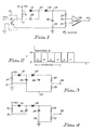
- FIGURE 1 is a schematic diagram of a sensing circuit embodying the invention;
- FIGURE 2 is a waveform representing the open collector transistor voltage of a fan circuit with which the sensing circuit can be used;
- FIGURE 3 is an equivalent circuit useful in understanding the operation of the sensing circuit of FIG. 1 with the open collector transistor in an on state; and
- FIGURE 4 is an equivalent circuit useful in understanding the operation of the sensing circuit of FIG. 1 with the open collector transistor in the off state.
- Referring to the drawings, and particularly to FIGURE 1, a preferred embodiment of the invention is described. Numeral 10 in FIGURE 1 identifies a portion of a basic cooling fan such as that commonly used to provide forced air cooling for semiconductor power supplies. As shown, the fan is commonly supplied with a +12 volt power supply input and has a grounded input, as well. The circuit details of the fan are conventional and are not illustrated. However, it should be understood that such fans usually have a DC rotor that provides an output signal when the fan is stopped. In the case of this type of fan, a rotation sensor provides a bias signal that controls an
open collector transistor 12, i.e. switches it on and off as the fan rotates. Thus, the operation of the rotation sensor and the fan produce an output in conventional fashion atnode 13 of the open collector circuit that comprises a pulse train similar to that illustrated in FIGURE 2 of the drawings. - Referring particularly to FIGURE 2, it can be seen that an alternating waveform is produced at
node 13 which is a pulse train varying between a +5 volt output and a .5 volt output. - Referring again to FIGURE 1, the sensing circuit embodying the invention will now be described. A +5 volt input is provided at a node 14, with a
resistor 15 being connected betweennode 13 and node 14. Adiode 18 is connected with the indicated polarity between node 14 andnode 20, and adiode 22 is connected betweennode 20 andnode 24, again with the indicated polarity. Acapacitor 26 is connected betweennode 13 andnode 20, and acapacitor 28 is connected betweennode 24 andnode 30.Resistors node 24 andnode 30 so that they are in electrical parallel withcapacitor 28.Node 30 is also connected to ground and to the emitter oftransistor 12. Anode 34 betweenresistors voltage sensing comparator 36, which also receives a +2.5 volt input on a second input fromnode 37. The output of the under voltage sensing comparator is provided onnode 40 and comprises a fan sense output signal. - When the power supply is turned on, the 12 volt signal is provided to the fan by the power supply circuit along with the 5 volt and 2.5 volt inputs illustrated in FIGURE 1. When the fan rotates, it generates the waveform shown in FIGURE 2 at the open collector circuit as indicated at
node 13. - Referring to FIGURE 2, as the transistor is turned on (in regions A, C, E of the waveform) current flows from the +5 volt supply through
diode 18 andcapacitor 26 to ground. This eventually chargescapacitor 26 to about 4 volts (+5V-VD18-Vce sat.). Whentransistor 12 is turned off (as indicated in regions B, D, and F of FIGURE 2),capacitor 28 will charge to about 8 volts (+5V+VC26-VD22). This charge is effected by the +5 volt signal applied throughresistor 15 and the voltage action ofcapacitor 26 discharging throughdiode 22. - When the transistor turns back on, as in region C,
capacitor 26 will again charge through thediode 18 to about 4 volts. During this time,capacitor 28 will start to discharge due to the voltage divider load of R32 and R33. However, since the voltage at C28 is higher than the voltage on C26,diode 22 will be reverse biased and have no effect upon the charging of C26. - In region D of the waveform, the transistor has again turned off, thus allowing C28 to charge again through
diode 22, C26 and the +5 volts supply. Due to this sequence, under normal operation, a steady state DC voltage is eventually developed atnode 24 which is higher than the +5 voltage at node 14, i.e. about 8 volts. The divider of R32 and R33 is used to divide the 8 volts down to a predetermined sense level of about 2.5 volts. - When the fan stops turning,
transistor 12 will provide an output of either a high voltage (+5V)or a low voltage (.5V) state. When the rotor stops with the transistor in the "on" state, the equivalent circuit is that shown in FIGURE 3.Capacitor 26 will charge to +4 volts.Capacitor 28 will initially be charged to about 8 volts and will start to decay due to the load ofresistor 32 andresistor 33. The voltage at C28 will decay until it reaches the 4 volts seen on C26. At this time,diode 22 will start to conduct allowing C28 to stay charged at a diode drop below the voltage of C26, i.e. about 3.5 volts. In view of the value of R32, the voltage atnode 34 is then below the under voltage sense point of 2.5V, causing an error signal from the comparator which can be utilized to shut the power supply off. - When the rotor stops with the transistor in the "off" state, the equivalent circuit is that shown in FIGURE 4 with no direct circuit connection between
node 13 andnode 30. Thus, C28 will discharge due to theresistor 32 andresistor 33 load, at the same time C26 is discharging into C28. C28 will continue to discharge until it reaches about 3.5 volts, at which time C26 will be completely discharged and D18 and D22 will be forward biased, maintaining C28 charged at about 3.5 volts. As occurs in the "on" state, the voltage atnode 34 is then below the under voltage sense point. This again causes the error signal to occur atnode 40, which can be used to turn the power supply off. - The most significant feature of this extremely low-cost circuit is that an under voltage signal will be developed no matter which state the fan sense transistor stops in, either "on" or "off".
- In the preferred embodiment component values were selected as follows:
R15 = 1K ohms,
R32 = 33.2K ohms,
R33 = 15K ohms,
C26 = 6.8 microfarads,
C28 = 15 microfarads.
Claims (7)
an input node (13) to receive the pulse train;
voltage conversion means (15, 18, 22, 26 and 28) connected to the input node for converting the pulses of the pulse train to a steady state DC signal level higher than the voltage level of the alternating pulses; and
comparator means (36) connected to the conversion means for comparing the DC signal level with a reference voltage, the comparator means producing an output when the DC level of the conversion means falls below the reference voltage level as a result of the absence of pulses from the pulse train regardless of the state in which the pulse train is interrupted.
a first terminal (13) connected to the pulse train source, a first resistor (15) connected between a voltage source terminal (14) and the first terminal;
a diode (18) having its anode connected to the voltage source terminal;
a capacitor (26) having one terminal connected to said first terminal and another terminal connected to the cathode of the first diode;
a second diode (22) having its anode connected to the cathode of the first diode and having its cathode connected to one terminal (24) of a second capacitor (28);
the other terminal of the second capacitor being connected to ground; and
second and third resistors (32, 33) connected in series between the cathode of the second diode and ground, and a comparator (36) receiving a first input from the junction (34) between said second and third resistors and receiving a second input from a reference signal terminal, and an output terminal connected to the output of the comparator for receiving a pulse error signal.
Applications Claiming Priority (2)
| Application Number | Priority Date | Filing Date | Title |
|---|---|---|---|
| US215183 | 1988-07-05 | ||
| US07/215,183 US4845379A (en) | 1988-07-05 | 1988-07-05 | Sense circuit for detecting absence of a pulse train |
Publications (2)
| Publication Number | Publication Date |
|---|---|
| EP0350184A2 true EP0350184A2 (en) | 1990-01-10 |
| EP0350184A3 EP0350184A3 (en) | 1990-12-05 |
Family
ID=22802003
Family Applications (1)
| Application Number | Title | Priority Date | Filing Date |
|---|---|---|---|
| EP19890306363 Withdrawn EP0350184A3 (en) | 1988-07-05 | 1989-06-23 | Pulse train interruption sensing circuit |
Country Status (3)
| Country | Link |
|---|---|
| US (1) | US4845379A (en) |
| EP (1) | EP0350184A3 (en) |
| JP (1) | JPH0247917A (en) |
Cited By (1)
| Publication number | Priority date | Publication date | Assignee | Title |
|---|---|---|---|---|
| EP0930710A3 (en) * | 1998-01-12 | 2005-10-05 | Fujitsu Limited | Clock signal detection circuit |
Families Citing this family (8)
| Publication number | Priority date | Publication date | Assignee | Title |
|---|---|---|---|---|
| JPH03139185A (en) * | 1989-10-24 | 1991-06-13 | Mita Ind Co Ltd | Abnormality detector for rotation detector |
| JP3656758B2 (en) * | 1991-05-08 | 2005-06-08 | 富士通株式会社 | Operating state detection circuit |
| US5589784A (en) * | 1992-03-31 | 1996-12-31 | Texas Instruments Incorporated | Method and apparatus for detecting changes in a clock signal to static states |
| US5399911A (en) * | 1994-02-14 | 1995-03-21 | General Electric Company | Pulse detection circuit |
| JPH11112158A (en) * | 1997-10-03 | 1999-04-23 | Toshiba Corp | Closed control device |
| US6255860B1 (en) * | 1998-07-16 | 2001-07-03 | Lucent Technologies Inc. | Pulse detection circuit, method of operation thereof and fan assembly test circuit employing the same |
| US6747424B1 (en) * | 2000-10-02 | 2004-06-08 | International Business Machines Corporation | Integrated fan speed control and fault detection circuitry |
| CN106932682B (en) * | 2017-03-23 | 2023-09-29 | 中国南方电网有限责任公司超高压输电公司南宁局 | Grounding loop detection method for one-point grounding of voltage total station |
Family Cites Families (26)
| Publication number | Priority date | Publication date | Assignee | Title |
|---|---|---|---|---|
| US3258669A (en) * | 1966-06-28 | Variable width fulse-fed micromotor control system | ||
| US2847565A (en) * | 1954-12-31 | 1958-08-12 | Ibm | Pulse gap detector |
| US3069558A (en) * | 1957-08-12 | 1962-12-18 | Westinghouse Electric Corp | Frequency sensitive control circuit |
| US3068367A (en) * | 1959-09-08 | 1962-12-11 | Burroughs Corp | Pulse train gap detector circuitry |
| US3149243A (en) * | 1961-07-14 | 1964-09-15 | Int Standard Electric Corp | Radio receiver including a monitoring circuit indicating an output upon input exceeding predetermined frequency |
| BE639144A (en) * | 1962-10-25 | |||
| US3305732A (en) * | 1963-06-10 | 1967-02-21 | Barnes Eng Co | Spurious signal void circuit |
| DE1220179B (en) * | 1963-10-17 | 1966-06-30 | Bosch Gmbh Robert | Arrangement for the limit speed measurement of a shaft |
| US3405234A (en) * | 1965-12-30 | 1968-10-08 | Ibm | Tone circuits for control and data signals |
| US3403269A (en) * | 1966-04-25 | 1968-09-24 | Techrand Corp Of America | Frequency responsive rc timing circuit for detecting either lack of input or overextended presence of input |
| US3506848A (en) * | 1967-04-12 | 1970-04-14 | Henry Richard Beurrier | Pulse width to analog signal converter |
| US3514685A (en) * | 1967-04-24 | 1970-05-26 | Fan Tron Corp | Optical speed transducer |
| ES357297A1 (en) * | 1967-08-17 | 1970-03-01 | Standard Electrica Sa | Tone detector |
| US3497816A (en) * | 1969-04-16 | 1970-02-24 | American Mach & Foundry | Frequency sensor and control circuit |
| US3653018A (en) * | 1970-06-08 | 1972-03-28 | Stromberg Carlson Corp | Monitor circuit |
| JPS5524320B2 (en) * | 1972-05-24 | 1980-06-27 | ||
| US3790818A (en) * | 1973-03-26 | 1974-02-05 | Ncr | Supply voltage and clock signal monitor |
| FR2336686A1 (en) * | 1975-12-24 | 1977-07-22 | Nguyen Van Trong | Moving body speed loss detector - has capacitive memory with controlled charge loss and has voltage threshold detector |
| FR2399026A1 (en) * | 1977-07-25 | 1979-02-23 | Asa Sa | Rotational speed detection system - is used for shafts with widely varying rates of rotation and includes mobile active element |
| US4158148A (en) * | 1977-11-17 | 1979-06-12 | Teller Howard S Jr | Latching detector circuit |
| JPS5567229A (en) * | 1978-11-14 | 1980-05-21 | Toshiba Electric Appliance Co Ltd | Pulse detection circuit |
| JPS55109968A (en) * | 1979-02-16 | 1980-08-23 | Nissan Motor Co Ltd | Frequency decision circuit |
| US4262213A (en) * | 1979-09-26 | 1981-04-14 | General Electric Company | Universal power module |
| JPS59194532A (en) * | 1983-04-20 | 1984-11-05 | Fujitsu Denso Ltd | Level deciding circuit |
| US4679508A (en) * | 1986-02-21 | 1987-07-14 | Westinghouse Electric Corp. | Transit vehicle door control apparatus |
| DE3610605A1 (en) * | 1986-03-29 | 1987-10-01 | Fichtel & Sachs Ag | FREQUENCY SWITCH |
-
1988
- 1988-07-05 US US07/215,183 patent/US4845379A/en not_active Expired - Fee Related
-
1989
- 1989-04-10 JP JP1088181A patent/JPH0247917A/en active Pending
- 1989-06-23 EP EP19890306363 patent/EP0350184A3/en not_active Withdrawn
Cited By (1)
| Publication number | Priority date | Publication date | Assignee | Title |
|---|---|---|---|---|
| EP0930710A3 (en) * | 1998-01-12 | 2005-10-05 | Fujitsu Limited | Clock signal detection circuit |
Also Published As
| Publication number | Publication date |
|---|---|
| US4845379A (en) | 1989-07-04 |
| JPH0247917A (en) | 1990-02-16 |
| EP0350184A3 (en) | 1990-12-05 |
Similar Documents
| Publication | Publication Date | Title |
|---|---|---|
| EP0284412B1 (en) | Automatic voltage switching power source | |
| US6630751B2 (en) | Excessive load capacitor detection circuit for UPS | |
| US4951171A (en) | Power supply monitoring circuitry for computer system | |
| US5636116A (en) | Synchronous rectifier impervious to reverse feed | |
| US20040263139A1 (en) | Switching type dc-dc converter | |
| US5426776A (en) | Microprocessor watchdog circuit | |
| EP0350184A2 (en) | Pulse train interruption sensing circuit | |
| US4317056A (en) | Voltage monitoring and indicating circuit | |
| US4783729A (en) | Automatic voltage doubler switch | |
| US5523669A (en) | Charging circuit capable of supplying DC voltage directly to power supply circuit when battery is removed | |
| US4739244A (en) | Vehicle generator with acceleration control override | |
| EP0286282B1 (en) | Method for detecting input ac voltage | |
| US5737163A (en) | DC-AC converter protection | |
| US4659978A (en) | Regulator overvoltage circuit | |
| US5804995A (en) | Monitoring circuit for a supply voltage | |
| CA1109122A (en) | Speed regulator | |
| JP3574599B2 (en) | Inrush current prevention circuit with input overvoltage limit function | |
| JPH09149631A (en) | Power supply apparatus | |
| JPH06113553A (en) | Ac adapter | |
| EP0079128B1 (en) | Regulator for a dynamo | |
| JPH053634A (en) | Battery charge / discharge circuit | |
| JPH06106020B2 (en) | Switching regulator | |
| JP2910175B2 (en) | Brushless motor | |
| JP2730112B2 (en) | Power reset circuit in DC two-wire sensor | |
| JP2500714B2 (en) | Solenoid abnormality detection circuit |
Legal Events
| Date | Code | Title | Description |
|---|---|---|---|
| PUAI | Public reference made under article 153(3) epc to a published international application that has entered the european phase |
Free format text: ORIGINAL CODE: 0009012 |
|
| AK | Designated contracting states |
Kind code of ref document: A2 Designated state(s): DE FR GB |
|
| 17P | Request for examination filed |
Effective date: 19900512 |
|
| PUAL | Search report despatched |
Free format text: ORIGINAL CODE: 0009013 |
|
| AK | Designated contracting states |
Kind code of ref document: A3 Designated state(s): DE FR GB |
|
| 17Q | First examination report despatched |
Effective date: 19920507 |
|
| STAA | Information on the status of an ep patent application or granted ep patent |
Free format text: STATUS: THE APPLICATION IS DEEMED TO BE WITHDRAWN |
|
| 18D | Application deemed to be withdrawn |
Effective date: 19930907 |