EP0350076A1 - Electronic clinical sphygmomanometer - Google Patents
Electronic clinical sphygmomanometer Download PDFInfo
- Publication number
- EP0350076A1 EP0350076A1 EP89112501A EP89112501A EP0350076A1 EP 0350076 A1 EP0350076 A1 EP 0350076A1 EP 89112501 A EP89112501 A EP 89112501A EP 89112501 A EP89112501 A EP 89112501A EP 0350076 A1 EP0350076 A1 EP 0350076A1
- Authority
- EP
- European Patent Office
- Prior art keywords
- signal
- pulse
- wave
- korotkoff
- blood pressure
- Prior art date
- Legal status (The legal status is an assumption and is not a legal conclusion. Google has not performed a legal analysis and makes no representation as to the accuracy of the status listed.)
- Granted
Links
Images


Classifications
-
- A—HUMAN NECESSITIES
- A61—MEDICAL OR VETERINARY SCIENCE; HYGIENE
- A61B—DIAGNOSIS; SURGERY; IDENTIFICATION
- A61B5/00—Measuring for diagnostic purposes; Identification of persons
- A61B5/02—Detecting, measuring or recording pulse, heart rate, blood pressure or blood flow; Combined pulse/heart-rate/blood pressure determination; Evaluating a cardiovascular condition not otherwise provided for, e.g. using combinations of techniques provided for in this group with electrocardiography or electroauscultation; Heart catheters for measuring blood pressure
- A61B5/021—Measuring pressure in heart or blood vessels
- A61B5/022—Measuring pressure in heart or blood vessels by applying pressure to close blood vessels, e.g. against the skin; Ophthalmodynamometers
- A61B5/02208—Measuring pressure in heart or blood vessels by applying pressure to close blood vessels, e.g. against the skin; Ophthalmodynamometers using the Korotkoff method
Definitions
- the present invention relates generally to an electronic clinical sphygmomanometer and, more particularly, to an electronic clinical sphygmomanometer for measuring blood pressure on the basis of a Korotkoff-sound signal in a pulse-wave gate signal.
- Japanese Patent Application No. 279225/1986 proposes an electronic clinical sphygmomanometer of the type which is arranged to utilize the correlation between a pulse-wave signal and a Korotkoff-sound signal to compare the level of the pulse-wave signal with a predetermined level, thereby creating a pulse-wave gate signal for the purpose of improving noise resistance.
- the wave forms of pulse-wave signals are not constant and, in addition, the correlation between pulse-wave signals and Korotkoff-sound signals is not constant.
- a Korotkoff-sound signal occasionally deviates from a pulse-wave gate, and it has therefore been difficult to reliably detect Korotkoff-sound signals.
- an electronic clinical sphygmomanometer comprises a Korotkoff-sound signal detecting means for detecting a Korotkoff-sound signal and outputting a predetermined Korotkoff-sound detection signal, a pulse-wave signal detecting means for detecting a pulse-wave signal, a pulse-wave gate signal generating means for generating a pulse-wave gate signal the duration of which corresponds to at least the period during which the level of the pulse-wave signal is higher than a predetermined threshold level by comparing the pulse-wave signal detected by the pulse-wave signal detecting means with the predetermined threshold level, and an extending means for extending the duration of the pulse wave gate signal by a predetermined time period when the aforesaid Korotkoff-sound detection signal is not provided in the pulse wave gate signal generated by the pulse-wave gate signal generating means.
- the extending means is arranged to serve during at least a measurement period allocated for the measurement of the systolic blood pressure.
- the Korotkoff-sound signal detecting means comprises a first filter circuit which efficiently passes a Korotkoff-sound signal component in a pressure close to the systolic blood pressure, a first single-shot circuit arranged to be triggered by the leading edge of a signal output from the first filter circuit to thereby output a Korotkoff-sound detection signal, a second filter circuit which efficiently passes a Korotkoff-sound signal component in a pressure close to the diastolic blood pressure, and a second single-shot circuit arranged to be triggered by the trailing edge of a signal output from the second filter circuit to thereby output a Korotkoff-sound detection signal.
- Fig. 1 is a block diagram showing an embodiment of an electronic clinical sphygmomanometer according to the present invention.
- a cuff denoted by 1
- a rubber tube denoted by 2
- a pump denoted by 3
- a high-speed exhaust valve denoted by 4
- HSEV high-speed exhaust valve
- a slow-speed exhaust valve (LSEV), denoted by 5, serves to decrease the pressure in the cuff 1 at a constant rate (for example, 2-3 mmHg/second).
- a pressure sensor (P-S), denoted by 6, serves to detect the pressure in the cuff 1 and output a cuff-pressure signal P.
- An amplifier (AMP), denoted by 7, serves to amplify the cuff-pressure signal P.
- a filter amplifier (F-AMP), denoted by 8 serves to extract a pulse-wave signal component AP from the cuff-pressure signal P and amplify the extracted signal component.
- An A/D converter (A/D) is denoted by 9, and this serves to convert either the cuff-pressure signal P or the pulse-wave signal AP into digital data.
- a microphone serves to pick up a Korotkoff-sound signal K.
- a filter comparator (F-CMP) 11 is arranged to efficiently pass a Korotkoff-sound signal in a pressure close to the diastolic blood pressure (for example, a signal component which ranges from 10 Hz to 80 Hz) and to compare the Korotkoff-sound signal with a predetermined threshold value and output a pulse signal KL representing the result of this comparison.
- a single-shot circuit denoted by 12, is arranged to output a pulse signal KLC of fixed pulse width (e.g., 40 ⁇ s) in response to the trailing edge of the KL signal.
- a filter comparator is denoted by 13, and this is arranged to efficiently pass a Korotkoff-sound signal in a pressure close to the systolic blood pressure (for example, a signal component which ranges from 10 Hz to 60 Hz) and to compare the Korotkoff-sound signal with a predetermined threshold value and output a pulse signal KH representing the result of this comparison.
- a single-shot circuit denoted by 14, is arranged to output a pulse signal KHC of fixed pulse width (e.g., 40 ⁇ s) in response to the leading edge of the KH signal.
- a central processing unit denoted by 15, is arranged to execute the main control of the electronic clinical sphygmomanometer.
- the CPU 15 is provided with interruption inputs I1, I2 and I3.
- a ROM is denoted by 16 and a control program to be executed by the CPU 15, for example, a control program such as that shown in Figs. 2, 3 and 4 is stored in the ROM 16.
- a RAM is denoted by 17, and is used as a work area by the CPU 15.
- a timer (TM) is denoted by 15-1, and is arranged to measure the duration of a predetermined time period (for example, 60 ms) until it reaches a time-out state.
- a liquid-crystal display (LCD), denoted by 18, serves to display the systolic blood pressure (SYS), the diastolic blood pressure (DIA), error information and so on.
- SYS systolic blood pressure
- DIA diastolic blood pressure
- a buzzer (BZ), denoted by 19, serves to inform a user of, for example, the completion of measurement.
- a measurement start switch (SW) is denoted by 20, and the user can actuate the switch 20 to command the sphygmomanometer to start a measurement operation.
- Fig. 2 is a flow chart of the control provided over the measurement of blood pressure in the embodiment.
- this control process is started.
- Step S1 the high-speed exhaust valve 4 is opened and, in Step S2, the process waits for the cuff pressure P to reach zero. If the cuff pressure P reaches zero, the high-speed exhaust valve 4 is closed in Step S3.
- Step S4 the process waits for the measurement start switch (SW) to be pressed. If the switch (SW) 20 is pressed, driving of the pump 3 is started in Step S5.
- Step S6 the process waits for the cuff pressure P to reach a set value (for example, 140 to 150 mmHg).
- Step S7 If the cuff pressure P reaches the set value, the driving of the pump 3 is stopped in Step S7.
- Step S8 the slow-speed exhaust valve 5 is opened. In this manner, the cuff pressure P is made to decrease at a constant rate (2.3 mmHg/second) and, during this time, the data sampling shown in Figs. 3 and 4(A) to 4(C) is executed.
- Step S9 it is determined whether an end-of-measurement flag ENDF is set to "1". After the systolic blood pressure SYS and the diastolic blood pressure DIA have been measured, the end-of-measurement flag ENDF is set to "1".
- Step S12 the diastolic blood pressure is displayed on the LCD 18. Incidentally, the systolic blood pressure SYS is displayed at a previous time. If the end-of-measurement flag ENDF is not set to "1", the process proceeds to Step S10, where it is determined whether or not the cuff pressure P is lower than a predetermined low pressure L (for example, 20 mmHg). If the cuff pressure P is not lower than the predetermined pressure L, it is determined that the cuff pressure P is within a measurable range, and the flow returns to Step S9.
- a predetermined low pressure L for example, 20 mmHg
- Step S11 the characters "ERROR" are displayed on the LCD 18.
- Step S13 the CPU 15 transmits a tone signal TONE to the buzzer 19.
- the tone signal TONE transmitted for the case of a normal end differs from that transmitted for the case of an abnormal end.
- Step S14 the slow speed exhaust valve 5 is closed, and the process returns to Step S1.
- Steps S1 to S3 the air remaining in the cuff 1 is exhausted at high speed and, in Step S4, the process waits for the next measurement to be started.
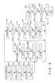
- Fig. 3 is a flow chart of data sampling executed in the embodiment. This process is started after Step S8 of Fig. 2 has been executed.
- Steps S21 to S25 a sequence of initialization steps is executed. More specifically, in Step S21, interruption-enable flags I1 to I3 (ENF) for the respective interruption routines I1, I2, and I3 are all reset to an interruption-unable state (0).
- Step S22 the contents of both a systolic-blood-pressure resistor SYSR and a diastolic-blood-pressure resistor DIAR are cleared.
- Step S23 a pulse-wave flag AUPF is cleared which indicates whether the level of the pulse-wave signal AP exceeds a return-line level T H .
- Step S24 the end-of-systolic-measurement flag SYSF and the detection-of-diastolic flag DIAF are cleared.
- Step S25 the end-of-measurement flag ENDF is cleared.
- Step S26 the pulse-wave signal AP is sampled.
- Step S27 it is determined whether the pulse-wave signal AP is higher than the return-line level T H . For example, if the pulse wave signal AP provided at the input of the A/D converter 9 ranges between 0 and 3 volts, the return-line level T H is 1 volt.
- Step S28 it is determined in Step S28 whether or not the value of the pulse-wave flag AUPF is "0". If it is determined, in Step S28, that the pulse-wave flag AUPF has the value 0, this indicates that the level of the pulse-wave signal AP has exceeded the return-line level T H . The process then proceeds to Step S29, in which "1" is set at the pulse-wave flag AUPF. In Step S30, it is determined whether or not the value of a end-of-systolic measurement flag SYSF is "1".
- Step S31 If the value of the end-of-systolic.measurement flag SYSF is not “1”, this indicates that the systolic blood pressure is being measured. Therefore, in Step S31, "1" is set in the interruption-enable flag I1ENF so that interruption based on the signal KHC is enabled. The time interval which elapses until this flag I1ENF is reset from “1" to "0" corresponds to the duration of a pulse-wave gate signal used for determining the systolic blood pressure. If it is determined, in Step S30, that the value of the end-of-systolic measurement flag SYSF is "1", this indicates that the diastolic blood pressure is being measured.
- Step S32 "1" is set in the interruption-enable flag I2ENF so that interruption based on the signal KLC is enabled.
- the time interval which elapses until this flag I2ENF is reset from “1" to "0" corresponds to the duration of a pulse-wave gate signal used for determining the diastolic blood pressure. If it is determined, in Step S28, that the value of the pulse-wave flag AUPF is not "0", this indicates that the level of the pulse-wave signal AP already exceeds the return-line level T H . The process then merely continues the sampling of the pulse-wave signal AP, waiting for the interruption routine I1 or I2 to be executed.
- Step S27 If it is determined, in Step S27, that the level of the pulse-wave signal AP is not higher than the return-line level T H , it is determined in Step S33 whether or not the value of the pulse-wave flag AUPF is "1". If it is determined that the pulse-wave flag AUPF has the value 1, this indicates that the level of the pulse-wave signal AP has dropped below the return-line level T H . The process proceeds to Step S34, in which "0" is set in the pulse-wave flag AUPF. In Step S35, it is determined whether or not the value of the interruption-enable flag I2ENF is "1".
- Step S36 the timer 15-1 (for measuring, e.g., 60 ms) is started to extend the duration of a pulse-wave gate signal used for determining the systolic blood pressure.
- Step S37 "1" is set in the timer-interruption-enable flag I3EHF so that timer interruption is enabled.
- Step S35 If it is determined, in Step S35, that the value of the interruption-enable flag I2ENF is "1", as in the case of the interruption-enable flag I1ENF mentioned above, it means that the signal KLC has not been generated during the period in which the value of the interruption-enable flag I2ENF is "1". In this embodiment, in such a case, the duration of the pulse-wave gate signal is not extended, and the process proceeds to Step S38, where "0" is set in the interruption-enable flag I2ENF. In Step S39, it is determined whether the value of the detection-of-diastolic flag DIAF is "1".
- Step S40 it is determined whether the state of no signal KLC being generated continues subsequently over a period corresponding to two beats during the period in which the interruption-enable flag I2ENF is "1".
- Step S26 If such a state does not occur during the period corresponding to two beats, the process returns to Step S26. If this state occurs during such period, it means that the end of the data sampling is normal. Then, the process proceeds to Step S41, where "1" is set in the end-of-measurement flag ENDF.
- Step S33 If it is determined, in Step S33, that the value of the pulse-wave flag AUPF is not "1", this indicates that the level of the pulse-wave signal AP has already fallen below the return-line level T H , and the process merely continues the sampling of the pulse-wave signal AP, waiting for the level of the pulse-wave signal AP to exceed the return-line level T H .
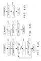
- Figs. 4(A) to 4(C) are flow charts of the interruption routines I1, I2, and I3, respectively.
- Step S51 If a signal KHC is generated during the period in which the value of the interruption-enable flag I1ENF is "1”, the process enters the interruption routine I1 shown in Fig. 4(A).
- Step S51 "0" is set in the interruption-enable flag I1ENF in order to prevent the interruption I1 from occurring repeatedly. Since the value of the interruption-enable flag I3ENF may be "1” at this point in time, "0” is also set in the interruption-enable flag I3ENF.
- the first data is stored in the resistor SYSR(1). Subsequently, the second and third data are likewise stored in the registers SYSR(2) and (3), respectively, so that the data corresponding to pulse waves for three beats are stored.
- Step S53 it is determined whether or not the data on the cuff pressures P for three pulse-wave beats have been stored. If it is determined that the data for three beats have not yet been stored, the process returns. If the data for three beats have been stored, this means that the data required to confirm the systolic blood pressure has been sampled.
- Step S54 "1" is set in the end-of-systolic-measurement flag SYSF and, in Step S55, the data which represents the blood pressure corresponding to the first beat is read from the systolic-blood-pressure resistors SYSR(1) and is in turn displayed on the LCD 18 as the systolic blood pressure SYS.
- Step S61 If a signal KLC is generated during the period in which the value of the interruption-enable flag I2ENF is "1", the process enters the interruption routine I2 shown in Fig. 4(B).
- Step S61 "0" is set in the interruption-enable flag I2ENF in order to prevent the interruption I2 from occurring repeatedly.
- Step S62 the cuff pressure P at the time of generation of the signal KLC is sampled, and data on the cuff-pressure P is stored in the diastolic-blood-pressure resistor DIAR. In this manner, the contents of the diastolic-pressure resister DIAR are rewritten with new sampled data. Since data has been detected which may represent the diastolic blood pressure, in Step S63, "1" is set in the diastolic-blood-pressure resistor DIAR.
- Step S71 If a time-out signal is generated during the period in which the value of the interruption-enable flag I3ENF is "1", the process enters the interruption routine I3 shown in Fig. 4(C).
- Step S71 "0" is set in the interruption-enable flag I3ENF.
- Step S72 "0” is also set in the interruption-enable flag I1ENF since the timer 15-1 has reached the time-out state (since 60 ms have elapsed), thereby closing the pulse-wave gate.
- Fig. 5 is a timing chart of the data sampling executed in the embodiment.
- a signal KH′ is a signal which has passed through the filter comparator (F-CMP) 13
- a signal KL′ is a signal which has passed through the filter comparator (F-CMP) 11.
- the duration of the pulse- wave gate signal KG is extended by 60 ms from the moment that the level of the pulse-wave signal AP falls below the return line level T H . This extension is executed in order to accommodate the phase relationship between the Korotkoff-sound signal KHC and the pulse-wave signal AP corresponding to a pressure close to the systolic blood pressure.
- This setting is likewise intended to accommodate the phase relationship between the Korotkoff-sound signal KLC and the pulse-wave signal AP corresponding to a pressure close to the diastolic blood pressure.
- the pulse-wave signal AP is separated and extracted from the detected cuff-pressure signal P
- the method of picking up the pulse-wave signal P is not limited to the above- described one.
- a microphone may be used to pick up a heart-beat signal and this heart-beat signal may be used as the pulse-wave signal AP.
- the above embodiment is explained with reference to the example in which the systolic blood pressure SYS and the diastolic blood pressure DIA are measured during the step of decreasing the cuff pressure while exhausting air from the cuff 1 at slow speeds, but this example is not construed as a limiting one.
- the diastolic blood pressure DIA and the systolic blood pressure SYS may be measured during the step of increasing the cuff pressure at a fixed speed. In this case, the pressure measured when a Korotkoff-sound signal appears corresponds to the diastolic blood pressure DIA, while the pressure measured when the Korotkoff-sound signal disappears corresponds to the systolic blood pressure SYS.
Abstract
Description
- The present invention relates generally to an electronic clinical sphygmomanometer and, more particularly, to an electronic clinical sphygmomanometer for measuring blood pressure on the basis of a Korotkoff-sound signal in a pulse-wave gate signal.
- In general, conventional clinical sphygmomanometers of this type are susceptible to external noise derived from such factors as motion of the body since Korotkoff-sound signals are weak, thus occasionally resulting in erroneous measurements. To eliminate such erroneous measurements, Japanese Patent Application No. 279225/1986 proposes an electronic clinical sphygmomanometer of the type which is arranged to utilize the correlation between a pulse-wave signal and a Korotkoff-sound signal to compare the level of the pulse-wave signal with a predetermined level, thereby creating a pulse-wave gate signal for the purpose of improving noise resistance.
- However, the wave forms of pulse-wave signals are not constant and, in addition, the correlation between pulse-wave signals and Korotkoff-sound signals is not constant. As a result, a Korotkoff-sound signal occasionally deviates from a pulse-wave gate, and it has therefore been difficult to reliably detect Korotkoff-sound signals.
- To eliminate the above-described problems with the prior art, it is a primary object of the present invention to provide an electronic clinical sphygmomanometer which is capable of effecting highly reliable measurement of blood pressure by forming an appropriate pulse-wave gate.
- According to the present invention the foregoing objects are attained by providing an electronic clinical sphygmomanometer comprises a Korotkoff-sound signal detecting means for detecting a Korotkoff-sound signal and outputting a predetermined Korotkoff-sound detection signal, a pulse-wave signal detecting means for detecting a pulse-wave signal, a pulse-wave gate signal generating means for generating a pulse-wave gate signal the duration of which corresponds to at least the period during which the level of the pulse-wave signal is higher than a predetermined threshold level by comparing the pulse-wave signal detected by the pulse-wave signal detecting means with the predetermined threshold level, and an extending means for extending the duration of the pulse wave gate signal by a predetermined time period when the aforesaid Korotkoff-sound detection signal is not provided in the pulse wave gate signal generated by the pulse-wave gate signal generating means.
- In a preferred embodiment, the extending means is arranged to serve during at least a measurement period allocated for the measurement of the systolic blood pressure.
- In a preferred embodiment, the Korotkoff-sound signal detecting means comprises a first filter circuit which efficiently passes a Korotkoff-sound signal component in a pressure close to the systolic blood pressure, a first single-shot circuit arranged to be triggered by the leading edge of a signal output from the first filter circuit to thereby output a Korotkoff-sound detection signal, a second filter circuit which efficiently passes a Korotkoff-sound signal component in a pressure close to the diastolic blood pressure, and a second single-shot circuit arranged to be triggered by the trailing edge of a signal output from the second filter circuit to thereby output a Korotkoff-sound detection signal.
- Other features and advantages of the present invention will be apparent from the following description taken in conjunction with the accompanying drawings, in which like reference characters designate the same or similar parts throughout the figures thereof.
-
- Fig. 1 is a block diagram showing an embodiment of an electronic clinical sphygmomanometer according to the present invention;
- Fig. 2 is a flow chart of control provided over the measurement of blood pressure in the embodiment;
- Fig. 3 is a flow chart of the data sampling executed in the embodiment;
- Figs. 4(A) to 4(C) are flow charts which show interruption routines I₁, I₂, and I₃, respectively; and
- Fig. 5 is a timing chart of the data sampling executed in the embodiment.
- An embodiment of the present invention will be described in detail below with reference to the accompanying drawings.
- Fig. 1 is a block diagram showing an embodiment of an electronic clinical sphygmomanometer according to the present invention. In the figure, a cuff, denoted by 1, is adapted to be wound around the upper arm of a person so as to constrict the artery. A rubber tube, denoted by 2, constitutes an inlet/outlet passage through which pressurized air is fed to, and discharged from, the
cuff 1. A pump, denoted by 3, serves to feed pressurized air into thecuff 1. A high-speed exhaust valve (HSEV), denoted by 4, serves to exhaust air from thecuff 1 at high speed. A slow-speed exhaust valve (LSEV), denoted by 5, serves to decrease the pressure in thecuff 1 at a constant rate (for example, 2-3 mmHg/second). A pressure sensor (P-S), denoted by 6, serves to detect the pressure in thecuff 1 and output a cuff-pressure signal P. An amplifier (AMP), denoted by 7, serves to amplify the cuff-pressure signal P. A filter amplifier (F-AMP), denoted by 8, serves to extract a pulse-wave signal component AP from the cuff-pressure signal P and amplify the extracted signal component. An A/D converter (A/D) is denoted by 9, and this serves to convert either the cuff-pressure signal P or the pulse-wave signal AP into digital data. A microphone, denoted by 10, serves to pick up a Korotkoff-sound signal K. A filter comparator (F-CMP) 11 is arranged to efficiently pass a Korotkoff-sound signal in a pressure close to the diastolic blood pressure (for example, a signal component which ranges from 10 Hz to 80 Hz) and to compare the Korotkoff-sound signal with a predetermined threshold value and output a pulse signal KL representing the result of this comparison. A single-shot circuit (SS), denoted by 12, is arranged to output a pulse signal KLC of fixed pulse width (e.g., 40 µs) in response to the trailing edge of the KL signal. A filter comparator (F-CMP) is denoted by 13, and this is arranged to efficiently pass a Korotkoff-sound signal in a pressure close to the systolic blood pressure (for example, a signal component which ranges from 10 Hz to 60 Hz) and to compare the Korotkoff-sound signal with a predetermined threshold value and output a pulse signal KH representing the result of this comparison. A single-shot circuit (SS), denoted by 14, is arranged to output a pulse signal KHC of fixed pulse width (e.g., 40 µs) in response to the leading edge of the KH signal. A central processing unit (CPU), denoted by 15, is arranged to execute the main control of the electronic clinical sphygmomanometer. TheCPU 15 is provided with interruption inputs I₁, I₂ and I₃. A ROM is denoted by 16 and a control program to be executed by theCPU 15, for example, a control program such as that shown in Figs. 2, 3 and 4 is stored in theROM 16. A RAM is denoted by 17, and is used as a work area by theCPU 15. A timer (TM) is denoted by 15-1, and is arranged to measure the duration of a predetermined time period (for example, 60 ms) until it reaches a time-out state. A liquid-crystal display (LCD), denoted by 18, serves to display the systolic blood pressure (SYS), the diastolic blood pressure (DIA), error information and so on. A buzzer (BZ), denoted by 19, serves to inform a user of, for example, the completion of measurement. A measurement start switch (SW) is denoted by 20, and the user can actuate theswitch 20 to command the sphygmomanometer to start a measurement operation. - Fig. 2 is a flow chart of the control provided over the measurement of blood pressure in the embodiment. When electrical power is supplied to the present apparatus, this control process is started. In Step S1, the high-
speed exhaust valve 4 is opened and, in Step S2, the process waits for the cuff pressure P to reach zero. If the cuff pressure P reaches zero, the high-speed exhaust valve 4 is closed in Step S3. In Step S4, the process waits for the measurement start switch (SW) to be pressed. If the switch (SW) 20 is pressed, driving of thepump 3 is started in Step S5. In Step S6, the process waits for the cuff pressure P to reach a set value (for example, 140 to 150 mmHg). If the cuff pressure P reaches the set value, the driving of thepump 3 is stopped in Step S7. In Step S8, the slow-speed exhaust valve 5 is opened. In this manner, the cuff pressure P is made to decrease at a constant rate (2.3 mmHg/second) and, during this time, the data sampling shown in Figs. 3 and 4(A) to 4(C) is executed. In Step S9, it is determined whether an end-of-measurement flag ENDF is set to "1". After the systolic blood pressure SYS and the diastolic blood pressure DIA have been measured, the end-of-measurement flag ENDF is set to "1". If the end-of-measurement flag ENDF is set to "1", this indicates that the end of the measurement is normal. Then, the process proceeds to Step S12, where the diastolic blood pressure is displayed on theLCD 18. Incidentally, the systolic blood pressure SYS is displayed at a previous time. If the end-of-measurement flag ENDF is not set to "1", the process proceeds to Step S10, where it is determined whether or not the cuff pressure P is lower than a predetermined low pressure L (for example, 20 mmHg). If the cuff pressure P is not lower than the predetermined pressure L, it is determined that the cuff pressure P is within a measurable range, and the flow returns to Step S9. If the cuff pressure P is lower than the predetermined pressure L, it is determined that the cuff pressure P has fallen below the measurable range, and the process proceeds to Step S11. In Step S11, the characters "ERROR" are displayed on theLCD 18. In Step S13, theCPU 15 transmits a tone signal TONE to thebuzzer 19. The tone signal TONE transmitted for the case of a normal end differs from that transmitted for the case of an abnormal end. In Step S14, the slowspeed exhaust valve 5 is closed, and the process returns to Step S1. In Steps S1 to S3, the air remaining in thecuff 1 is exhausted at high speed and, in Step S4, the process waits for the next measurement to be started. - Fig. 3 is a flow chart of data sampling executed in the embodiment. This process is started after Step S8 of Fig. 2 has been executed. In Steps S21 to S25, a sequence of initialization steps is executed. More specifically, in Step S21, interruption-enable flags I₁ to I₃ (ENF) for the respective interruption routines I₁, I₂, and I₃ are all reset to an interruption-unable state (0). In Step S22, the contents of both a systolic-blood-pressure resistor SYSR and a diastolic-blood-pressure resistor DIAR are cleared. In Step S23, a pulse-wave flag AUPF is cleared which indicates whether the level of the pulse-wave signal AP exceeds a return-line level TH. In Step S24, the end-of-systolic-measurement flag SYSF and the detection-of-diastolic flag DIAF are cleared. In Step S25, the end-of-measurement flag ENDF is cleared.
- In Step S26, the pulse-wave signal AP is sampled. In Step S27, it is determined whether the pulse-wave signal AP is higher than the return-line level TH. For example, if the pulse wave signal AP provided at the input of the A/
D converter 9 ranges between 0 and 3 volts, the return-line level TH is 1 volt. - If the level of the pulse-wave signal AP is higher than the return-line level TH, it is determined in Step S28 whether or not the value of the pulse-wave flag AUPF is "0". If it is determined, in Step S28, that the pulse-wave flag AUPF has the
value 0, this indicates that the level of the pulse-wave signal AP has exceeded the return-line level TH. The process then proceeds to Step S29, in which "1" is set at the pulse-wave flag AUPF. In Step S30, it is determined whether or not the value of a end-of-systolic measurement flag SYSF is "1". If the value of the end-of-systolic.measurement flag SYSF is not "1", this indicates that the systolic blood pressure is being measured. Therefore, in Step S31, "1" is set in the interruption-enable flag I₁ENF so that interruption based on the signal KHC is enabled. The time interval which elapses until this flag I₁ENF is reset from "1" to "0" corresponds to the duration of a pulse-wave gate signal used for determining the systolic blood pressure. If it is determined, in Step S30, that the value of the end-of-systolic measurement flag SYSF is "1", this indicates that the diastolic blood pressure is being measured. Therefore, in Step S32, "1" is set in the interruption-enable flag I₂ENF so that interruption based on the signal KLC is enabled. The time interval which elapses until this flag I₂ENF is reset from "1" to "0" corresponds to the duration of a pulse-wave gate signal used for determining the diastolic blood pressure. If it is determined, in Step S28, that the value of the pulse-wave flag AUPF is not "0", this indicates that the level of the pulse-wave signal AP already exceeds the return-line level TH. The process then merely continues the sampling of the pulse-wave signal AP, waiting for the interruption routine I₁ or I₂ to be executed. - If it is determined, in Step S27, that the level of the pulse-wave signal AP is not higher than the return-line level TH, it is determined in Step S33 whether or not the value of the pulse-wave flag AUPF is "1". If it is determined that the pulse-wave flag AUPF has the
value 1, this indicates that the level of the pulse-wave signal AP has dropped below the return-line level TH. The process proceeds to Step S34, in which "0" is set in the pulse-wave flag AUPF. In Step S35, it is determined whether or not the value of the interruption-enable flag I₂ENF is "1". If the value of the interruption-enable flag I₂ENF is not "1", this indicates that the level of the pulse-wave signal AP has dropped below the return-line level TH when the value of the interruption-enable flag I₂ENF is "1". This fact means that a signal KHC has not yet been generated during the period in which the value of the interruption-enable flag I₁ENF is "1". The flow then proceeds to Step S36, where the timer 15-1 (for measuring, e.g., 60 ms) is started to extend the duration of a pulse-wave gate signal used for determining the systolic blood pressure. In Step S37, "1" is set in the timer-interruption-enable flag I₃EHF so that timer interruption is enabled. - If it is determined, in Step S35, that the value of the interruption-enable flag I₂ENF is "1", as in the case of the interruption-enable flag I₁ENF mentioned above, it means that the signal KLC has not been generated during the period in which the value of the interruption-enable flag I₂ENF is "1". In this embodiment, in such a case, the duration of the pulse-wave gate signal is not extended, and the process proceeds to Step S38, where "0" is set in the interruption-enable flag I₂ENF. In Step S39, it is determined whether the value of the detection-of-diastolic flag DIAF is "1". If the value of the detection-of-diastolic flag DIAF is not "1", this means that no signal KLC has been sampled within the duration of the pulse-wave gate. Therefore, the process returns to Step S26. If the value of the detection-of-diastolic flag DIAF is "1", this means that at least one signal KLC has been sampled within the duration of the pulse-wave gate signal used for determining the diastolic blood pressure. The process, therefore, proceeds to Step S40, where it is determined whether the state of no signal KLC being generated continues subsequently over a period corresponding to two beats during the period in which the interruption-enable flag I₂ENF is "1". If such a state does not occur during the period corresponding to two beats, the process returns to Step S26. If this state occurs during such period, it means that the end of the data sampling is normal. Then, the process proceeds to Step S41, where "1" is set in the end-of-measurement flag ENDF.
- If it is determined, in Step S33, that the value of the pulse-wave flag AUPF is not "1", this indicates that the level of the pulse-wave signal AP has already fallen below the return-line level TH, and the process merely continues the sampling of the pulse-wave signal AP, waiting for the level of the pulse-wave signal AP to exceed the return-line level TH.
- Figs. 4(A) to 4(C) are flow charts of the interruption routines I₁, I₂, and I₃, respectively.
- If a signal KHC is generated during the period in which the value of the interruption-enable flag I₁ENF is "1", the process enters the interruption routine I₁ shown in Fig. 4(A). In Step S51, "0" is set in the interruption-enable flag I₁ENF in order to prevent the interruption I₁ from occurring repeatedly. Since the value of the interruption-enable flag I₃ENF may be "1" at this point in time, "0" is also set in the interruption-enable flag I₃ENF. In Step S52, the cuff pressure P at the time of generation of the signal KHC is sampled, and data on the cuff-pressure P are stored in systolic-blood-pressure resistors SYSR(n: n = 1, 2, 3). The first data is stored in the resistor SYSR(1). Subsequently, the second and third data are likewise stored in the registers SYSR(2) and (3), respectively, so that the data corresponding to pulse waves for three beats are stored. In Step S53, it is determined whether or not the data on the cuff pressures P for three pulse-wave beats have been stored. If it is determined that the data for three beats have not yet been stored, the process returns. If the data for three beats have been stored, this means that the data required to confirm the systolic blood pressure has been sampled. Accordingly, in Step S54, "1" is set in the end-of-systolic-measurement flag SYSF and, in Step S55, the data which represents the blood pressure corresponding to the first beat is read from the systolic-blood-pressure resistors SYSR(1) and is in turn displayed on the
LCD 18 as the systolic blood pressure SYS. - If a signal KLC is generated during the period in which the value of the interruption-enable flag I₂ENF is "1", the process enters the interruption routine I₂ shown in Fig. 4(B). In Step S61, "0" is set in the interruption-enable flag I₂ENF in order to prevent the interruption I₂ from occurring repeatedly. In Step S62, the cuff pressure P at the time of generation of the signal KLC is sampled, and data on the cuff-pressure P is stored in the diastolic-blood-pressure resistor DIAR. In this manner, the contents of the diastolic-pressure resister DIAR are rewritten with new sampled data. Since data has been detected which may represent the diastolic blood pressure, in Step S63, "1" is set in the diastolic-blood-pressure resistor DIAR.
- If a time-out signal is generated during the period in which the value of the interruption-enable flag I₃ENF is "1", the process enters the interruption routine I₃ shown in Fig. 4(C). In Step S71, "0" is set in the interruption-enable flag I₃ENF. In Step S72, "0" is also set in the interruption-enable flag I₁ENF since the timer 15-1 has reached the time-out state (since 60 ms have elapsed), thereby closing the pulse-wave gate.
- Fig. 5 is a timing chart of the data sampling executed in the embodiment. In the figure, a signal KH′ is a signal which has passed through the filter comparator (F-CMP) 13, and a signal KL′ is a signal which has passed through the filter comparator (F-CMP) 11. The left half of Fig. 5 shows the states of respective signals during the period of measurement of the systolic blood pressure (the value of the flag SYSF = "0"). As shown in this left half, a pulse-wave gate signal KG (the value of the flag I₁ENF = "1") is reset if the signal KHC is generated during the duration of the pulse-wave gate signal KG. If no signal KHC is generated during the same, the duration of the pulse- wave gate signal KG is extended by 60 ms from the moment that the level of the pulse-wave signal AP falls below the return line level TH. This extension is executed in order to accommodate the phase relationship between the Korotkoff-sound signal KHC and the pulse-wave signal AP corresponding to a pressure close to the systolic blood pressure.
- The right half of Fig. 5 shows the states of the respective signals during the period of measurement of the diastolic blood pressure (the value of the flag SYSF = "1"). As shown in this right half, the pulse-wave gate signal KG (the value of the flag I₂ENF = "1") is reset if the signal KLC is generated during the duration of the pulse-wave gate signal KG. If no signal KLC is generated during the same, the pulse-wave gate signal KG is reset at the time that the level of the pulse-wave signal AP falls below the return-line level TH. This setting is likewise intended to accommodate the phase relationship between the Korotkoff-sound signal KLC and the pulse-wave signal AP corresponding to a pressure close to the diastolic blood pressure.
- Although in the above-described embodiment the pulse-wave signal AP is separated and extracted from the detected cuff-pressure signal P, the method of picking up the pulse-wave signal P is not limited to the above- described one. As another example, a microphone may be used to pick up a heart-beat signal and this heart-beat signal may be used as the pulse-wave signal AP.
- The above embodiment is explained with reference to the example in which the systolic blood pressure SYS and the diastolic blood pressure DIA are measured during the step of decreasing the cuff pressure while exhausting air from the
cuff 1 at slow speeds, but this example is not construed as a limiting one. As another example, the diastolic blood pressure DIA and the systolic blood pressure SYS may be measured during the step of increasing the cuff pressure at a fixed speed. In this case, the pressure measured when a Korotkoff-sound signal appears corresponds to the diastolic blood pressure DIA, while the pressure measured when the Korotkoff-sound signal disappears corresponds to the systolic blood pressure SYS. - As described above, in accordance with the present invention, since a pulse-wave gate is always accurately opened with respect to the duration of a Korotkoff-sound signal, it is possible to effect highly reliable measurement of blood pressure.
- As many apparently widely different embodiments of the present invention can be made without departing from the spirit and scope thereof, it is to be understood that the invention is not limited to the specific embodiments thereof except as defined in the appended claims.
Claims (3)
Korotkoff-sound signal detecting means for detecting a Korotkoff-sound signal and outputting a predetermined Korotkoff-sound detection signal;
pulse-wave signal detecting means for detecting a pulse-wave signal;
pulse-wave gate signal generating means for generating a pulse-wave gate signal the duration of which corresponds to at least a period over which the level of said pulse-wave signal is higher than a predetermined threshold level by comparing said pulse-wave signal detected by said pulse-wave signal detecting means with said predetermined threshold level; and
extending means for extending the duration of said pulse-wave gate signal by a predetermined time period when said Korotkoff-sound detection signal is not provided in said pulse-wave gate signal generated by said pulse-wave gate signal generating means.
Applications Claiming Priority (2)
| Application Number | Priority Date | Filing Date | Title |
|---|---|---|---|
| JP63167837A JPH0219135A (en) | 1988-07-07 | 1988-07-07 | Electronic sphygmomanometer |
| JP167837/88 | 1988-07-07 |
Publications (2)
| Publication Number | Publication Date |
|---|---|
| EP0350076A1 true EP0350076A1 (en) | 1990-01-10 |
| EP0350076B1 EP0350076B1 (en) | 1994-01-19 |
Family
ID=15857001
Family Applications (1)
| Application Number | Title | Priority Date | Filing Date |
|---|---|---|---|
| EP89112501A Expired - Lifetime EP0350076B1 (en) | 1988-07-07 | 1989-07-07 | Electronic clinical sphygmomanometer |
Country Status (4)
| Country | Link |
|---|---|
| US (1) | US4971064A (en) |
| EP (1) | EP0350076B1 (en) |
| JP (1) | JPH0219135A (en) |
| DE (1) | DE68912425T2 (en) |
Cited By (1)
| Publication number | Priority date | Publication date | Assignee | Title |
|---|---|---|---|---|
| US5135003A (en) * | 1987-08-11 | 1992-08-04 | Terumo Kabushiki Kaisha | Automatic sphygmomanometer |
Families Citing this family (3)
| Publication number | Priority date | Publication date | Assignee | Title |
|---|---|---|---|---|
| US5165416A (en) * | 1990-08-23 | 1992-11-24 | Colin Electronics Co., Ltd. | Continuous blood pressure monitoring system having a digital cuff calibration system and method |
| US5406954A (en) * | 1992-01-13 | 1995-04-18 | Tomita; Mitsuei | Apparatus for detecting and displaying blood circulatory information |
| JP5600023B2 (en) * | 2010-03-26 | 2014-10-01 | テルモ株式会社 | Electronic blood pressure monitor |
Citations (4)
| Publication number | Priority date | Publication date | Assignee | Title |
|---|---|---|---|---|
| US4261368A (en) * | 1979-04-23 | 1981-04-14 | Welch Allyn, Inc. | Electronic blood pressure device |
| EP0053228B1 (en) * | 1980-12-03 | 1984-08-22 | Clinical Data, Inc. | Blood pressure measurement apparatus |
| EP0154995A2 (en) * | 1984-03-13 | 1985-09-18 | Omron Tateisi Electronics Co. | Device for measuring blood pressure |
| GB2165052A (en) * | 1984-09-27 | 1986-04-03 | Copal Takeda Medical Lab Inc | Automatically measuring blood pressure |
Family Cites Families (6)
| Publication number | Priority date | Publication date | Assignee | Title |
|---|---|---|---|---|
| JPS5444378A (en) * | 1977-09-14 | 1979-04-07 | Omron Tateisi Electronics Co | System of deciding minimum blood pressure in automatic blood pressure measuring device |
| CH644260A5 (en) * | 1980-02-18 | 1984-07-31 | Asulab Ag | BLOOD PRESSURE MEASURING DEVICE. |
| DE3116387C2 (en) * | 1981-04-24 | 1983-11-10 | Asulab AG, 2502 Bienne | Method of measuring a person's blood pressure and blood pressure measuring device |
| JPS59108535A (en) * | 1982-12-10 | 1984-06-23 | 三洋電機株式会社 | Hemomanometer |
| JPS59146638A (en) * | 1983-02-14 | 1984-08-22 | シャープ株式会社 | Blood pressure measuring device |
| JPS62233142A (en) * | 1986-04-03 | 1987-10-13 | テルモ株式会社 | Blood pressure measuring device |
-
1988
- 1988-07-07 JP JP63167837A patent/JPH0219135A/en not_active Withdrawn
-
1989
- 1989-07-06 US US07/375,921 patent/US4971064A/en not_active Expired - Lifetime
- 1989-07-07 DE DE68912425T patent/DE68912425T2/en not_active Expired - Fee Related
- 1989-07-07 EP EP89112501A patent/EP0350076B1/en not_active Expired - Lifetime
Patent Citations (4)
| Publication number | Priority date | Publication date | Assignee | Title |
|---|---|---|---|---|
| US4261368A (en) * | 1979-04-23 | 1981-04-14 | Welch Allyn, Inc. | Electronic blood pressure device |
| EP0053228B1 (en) * | 1980-12-03 | 1984-08-22 | Clinical Data, Inc. | Blood pressure measurement apparatus |
| EP0154995A2 (en) * | 1984-03-13 | 1985-09-18 | Omron Tateisi Electronics Co. | Device for measuring blood pressure |
| GB2165052A (en) * | 1984-09-27 | 1986-04-03 | Copal Takeda Medical Lab Inc | Automatically measuring blood pressure |
Cited By (1)
| Publication number | Priority date | Publication date | Assignee | Title |
|---|---|---|---|---|
| US5135003A (en) * | 1987-08-11 | 1992-08-04 | Terumo Kabushiki Kaisha | Automatic sphygmomanometer |
Also Published As
| Publication number | Publication date |
|---|---|
| US4971064A (en) | 1990-11-20 |
| DE68912425D1 (en) | 1994-03-03 |
| DE68912425T2 (en) | 1994-07-28 |
| JPH0219135A (en) | 1990-01-23 |
| EP0350076B1 (en) | 1994-01-19 |
Similar Documents
| Publication | Publication Date | Title |
|---|---|---|
| US5253648A (en) | Method and apparatus for excluding artifacts from automatic blood pressure measurements | |
| US5054494A (en) | Oscillometric blood pressure device | |
| US4154238A (en) | Apparatus and process using second derivative of oscillometric waveform for producing sphygmometric information | |
| US5135003A (en) | Automatic sphygmomanometer | |
| EP0422512B1 (en) | Electronic sphygmomanometer | |
| US20040147848A1 (en) | Blood pressure measuring apparatus | |
| EP0456844A1 (en) | Non-invasive automatic blood pressure measuring apparatus | |
| JPH07136136A (en) | Continuous blood pressure monitoring system | |
| JPH0191835A (en) | Electronic hemomanometer | |
| JP2000000217A (en) | Continuous blood pressure measurement system for dialysis | |
| US5522395A (en) | Electronic sphygmomanometer and method of controlling operation of same | |
| US6561985B2 (en) | Automatic blood-pressure measuring apparatus | |
| JPH01101967A (en) | Electronic hemomanometer | |
| US8920328B2 (en) | Blood pressure measurement apparatus | |
| JPH0512933B2 (en) | ||
| US6786872B2 (en) | Augmentation-index measuring apparatus | |
| EP0350076B1 (en) | Electronic clinical sphygmomanometer | |
| JPS62275434A (en) | Blood pressure measuring apparatus | |
| JPS61122840A (en) | Method and apparatus for controlling cuff pressure | |
| EP1410757A1 (en) | Vital-information obtaining apparatus | |
| JP2506119B2 (en) | Electronic blood pressure monitor | |
| JP3171928B2 (en) | Electronic sphygmomanometer | |
| US6582373B2 (en) | Automatic blood-pressure measuring apparatus | |
| JPH05168601A (en) | Electronic sphygmomanometer | |
| JP3025075B2 (en) | Electronic sphygmomanometer |
Legal Events
| Date | Code | Title | Description |
|---|---|---|---|
| PUAI | Public reference made under article 153(3) epc to a published international application that has entered the european phase |
Free format text: ORIGINAL CODE: 0009012 |
|
| 17P | Request for examination filed |
Effective date: 19890804 |
|
| AK | Designated contracting states |
Kind code of ref document: A1 Designated state(s): BE DE FR GB IT NL SE |
|
| 17Q | First examination report despatched |
Effective date: 19930402 |
|
| RBV | Designated contracting states (corrected) |
Designated state(s): DE FR IT |
|
| GRAA | (expected) grant |
Free format text: ORIGINAL CODE: 0009210 |
|
| AK | Designated contracting states |
Kind code of ref document: B1 Designated state(s): DE FR IT |
|
| ITF | It: translation for a ep patent filed |
Owner name: FUMERO BREVETTI S.N.C. |
|
| REF | Corresponds to: |
Ref document number: 68912425 Country of ref document: DE Date of ref document: 19940303 |
|
| ET | Fr: translation filed | ||
| PLBE | No opposition filed within time limit |
Free format text: ORIGINAL CODE: 0009261 |
|
| STAA | Information on the status of an ep patent application or granted ep patent |
Free format text: STATUS: NO OPPOSITION FILED WITHIN TIME LIMIT |
|
| 26N | No opposition filed | ||
| PGFP | Annual fee paid to national office [announced via postgrant information from national office to epo] |
Ref country code: DE Payment date: 20060629 Year of fee payment: 18 |
|
| PGFP | Annual fee paid to national office [announced via postgrant information from national office to epo] |
Ref country code: FR Payment date: 20060719 Year of fee payment: 18 |
|
| PGFP | Annual fee paid to national office [announced via postgrant information from national office to epo] |
Ref country code: IT Payment date: 20060731 Year of fee payment: 18 |
|
| PG25 | Lapsed in a contracting state [announced via postgrant information from national office to epo] |
Ref country code: DE Free format text: LAPSE BECAUSE OF NON-PAYMENT OF DUE FEES Effective date: 20080201 |
|
| REG | Reference to a national code |
Ref country code: FR Ref legal event code: ST Effective date: 20080331 |
|
| PG25 | Lapsed in a contracting state [announced via postgrant information from national office to epo] |
Ref country code: FR Free format text: LAPSE BECAUSE OF NON-PAYMENT OF DUE FEES Effective date: 20070731 |
|
| PG25 | Lapsed in a contracting state [announced via postgrant information from national office to epo] |
Ref country code: IT Free format text: LAPSE BECAUSE OF NON-PAYMENT OF DUE FEES Effective date: 20070707 |