EP0349930A2 - Switch with pre-alarm means - Google Patents
Switch with pre-alarm means Download PDFInfo
- Publication number
- EP0349930A2 EP0349930A2 EP89112004A EP89112004A EP0349930A2 EP 0349930 A2 EP0349930 A2 EP 0349930A2 EP 89112004 A EP89112004 A EP 89112004A EP 89112004 A EP89112004 A EP 89112004A EP 0349930 A2 EP0349930 A2 EP 0349930A2
- Authority
- EP
- European Patent Office
- Prior art keywords
- switch
- alarm
- level
- current
- value
- Prior art date
- Legal status (The legal status is an assumption and is not a legal conclusion. Google has not performed a legal analysis and makes no representation as to the accuracy of the status listed.)
- Granted
Links
Images


Classifications
-
- H—ELECTRICITY
- H01—ELECTRIC ELEMENTS
- H01H—ELECTRIC SWITCHES; RELAYS; SELECTORS; EMERGENCY PROTECTIVE DEVICES
- H01H71/00—Details of the protective switches or relays covered by groups H01H73/00 - H01H83/00
- H01H71/04—Means for indicating condition of the switching device
-
- H—ELECTRICITY
- H01—ELECTRIC ELEMENTS
- H01H—ELECTRIC SWITCHES; RELAYS; SELECTORS; EMERGENCY PROTECTIVE DEVICES
- H01H73/00—Protective overload circuit-breaking switches in which excess current opens the contacts by automatic release of mechanical energy stored by previous operation of a hand reset mechanism
- H01H73/02—Details
- H01H73/12—Means for indicating condition of the switch
- H01H73/14—Indicating lamp structurally associated with the switch
-
- H—ELECTRICITY
- H02—GENERATION; CONVERSION OR DISTRIBUTION OF ELECTRIC POWER
- H02H—EMERGENCY PROTECTIVE CIRCUIT ARRANGEMENTS
- H02H3/00—Emergency protective circuit arrangements for automatic disconnection directly responsive to an undesired change from normal electric working condition with or without subsequent reconnection ; integrated protection
- H02H3/006—Calibration or setting of parameters
-
- H—ELECTRICITY
- H02—GENERATION; CONVERSION OR DISTRIBUTION OF ELECTRIC POWER
- H02H—EMERGENCY PROTECTIVE CIRCUIT ARRANGEMENTS
- H02H3/00—Emergency protective circuit arrangements for automatic disconnection directly responsive to an undesired change from normal electric working condition with or without subsequent reconnection ; integrated protection
- H02H3/02—Details
- H02H3/04—Details with warning or supervision in addition to disconnection, e.g. for indicating that protective apparatus has functioned
Definitions
- the present invention relates to a switch with pre-alarm means for alarming that an abnormal current flows on breaker of the switch prior to an actual tripping operation of the breaker, and especially relates to a switch with pre-alarm means to be used for measuring effective value of the current flowing on the breaker or on the load by using pre alarm function thereof.
- an ammeter or a current transformer which is clamped or disposed on electric power lines or breaker of the switch, has been conventionally used.
- peak value of the current has been measured generally.
- a circuit for measuring the effective value is necessary to be provided on tripping circuit of the switch.
- Object of the present invention is to provide an improved switch with pre-alarm means for measuring value of current flowing on load by using pre-alarm function included in the switch.
- a switch with pre-alarm means in accordance with the present invention comprises: pre-alarm means for alarming that abnormal current which is above a predetermined level flows on breaker of the switch previous to tripping of the breaker; operation indicator means for indicating operations of the pre-alarm means, which is provided on outer face of housing of the switch to be confirmed of the operation; level adjusting means for adjusting the predetermined level within a range below a rated value of current, which is provided on outer face of the housing: and level indicator means for indicating the predetermined level.
- the switch with pre-alarm means in accordance with the present invention is constructed as mentioned above, when a user operates the level adjusting means for reducing the level of the pre-alarm means gradually from the rated value of the current with monitoring the indication of the operation indicator, the operation indicator means alarms by, for example, lighting of an alarm lamp.
- the indication by the level indicator means corresponds to the value of the current flowing on the load at that time. Thereby, the value of the current flowing on the load can easily be measured.
- FIGs.1, 2, 3, 4 and 5 A preferred embodiment of a switch with pre-alarm means in accordance with the present invention is described referring to FIGs.1, 2, 3, 4 and 5.
- FIG.1 is a perspective view showing a switch with pre-alarm means in accordance with the present invention.
- the switch 101 comprises a breaker and a pre-alarm apparatus in a housing 102.
- An operation indicator 103 which is, for example, a light emitted diode (LED) is provided on outer face of the housing 102, thereby an operator can easily confirm the operation indicator 103.
- a reset switch 108 is also provided on the outer face of the housing 102.
- a lug 104 is for changing rated value of current of the switch 101, and lug 105a is for adjusting level of the pre-alarm of the switch.
- the lug 105a a is rotatable and co-axially connected to a variable resistor such as VR1 shown in FIG.
- a level indicator 105b such as scale for current (A) is provided around the lug 105a. thereby the level of the pre-alarm can be confirmed.
- numeral 106 designates an operation lever of the breaker installed in the housing 102 for making and breaking contacts thereof; and numerals 107, 107... designate terminals of the switch 101 to be connected to electric power lines and loads.
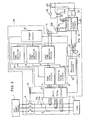
- FIG.3 is a circuit diagram of the switch with pre-alarm means in accordance with the present invention.
- current transformers CTa, CTb and CTc are disposed on three phases of A.C. power lines 5a, 5b and 5c, respectively.
- Output of secondary windings of the current transformers CTa, CTb and CTc are inputted to a rectifying circuit 6.
- Outputs of the rectifying circuit 6 is inputted to a peak value circuit 7 and an effective value circuit 8.
- the peak value circuit 7 selects an output from the rectifying circuit 6 corresponding to an output of the current transformers CTa, CTb and CTc including maximum value and converting the output to a peak value.
- the effective value circuit 8 also selects an output from the rectifying circuit 6 including maximum value and converting the output to an effective value. Output of the peak value circuit 7 is inputted to an instant time operation circuit 9 and a short time operation circuit 10. Output of the effective value circuit 8 is inputted to a long time operation circuit 11 and a pre-alarm circuit 20.
- the instant time operation circuit 9, the short time operation circuit 10 and the long time operation circuit 11 are connected to a trigger circuit 12, respectively.
- the trigger circuit 12 is connected to a tripping coil 13 and the rectifying circuit 6.
- the other terminal of the tripping coil 13 is also connected to the rectifying circuit 6.
- a light emitting diode (LED) 14 for indicating occurrence of over-current is connected to the long time operation circuit 11.
- the pre-alarm circuit 20 is connected to a pre-alarm output circuit 21 via photo-coupler 27.
- a light emitting diode (LED) 103 for pre- alarming and a relay coil 24 for pre-alarming are connected to the pre-alarm output circuit 21.
- An electric power source 23 for controlling the switch 101 is connected to the pre-alarm output circuit 21 via a voltage dropping element 22 such as a voltage transformer (VT).
- An alarm buzzer 26 is connected to the power source 23 via switch 24a.
- the switch 24a is opened and closed by operation of the relay coil 24 for pre-alarming, thereby the alarm buzzer 26 is controlled.
- FIG.4 is a circuit diagram for showing details of the pre-alarm circuit 20 in FIG.3.
- terminals designated by V+, V- and SGND are respectively connected to an electric power source of an over-current tripping circuit which is not shown in the drawings because of obviousness.
- V ref is a reference voltage, which is kept, for example, at 4V.
- Voltage at a terminal designated by VR ref is changeable due to the rated value of the current and set at, for example, 4V when the rated value is 400A and set at 2V when the rated value is 200A.
- Non-inverted terminal of a first comparator CM1 is connected to a variable resistor VR1 and voltage thereof is changed by the setting of the variable resistor VR1.
- the variable resistor VR1 is used for setting the pre-alarm level of the value of the current, and co-axially provided on the lug 105a shown in FIG.1.
- a D.C. signal which is in proportion to the effective value of the current flowing on a main circuit, for example, electric power line 5a, 5b or 5c is applied to a terminal designated by RMST.
- signals on the terminal designated by RMST is the output of the effective value circuit 8.
- V ref of the first comparator CM1 When the level of the D.C. signal on the terminal of RMST is above the reference voltage V ref of the first comparator CM1, a switch Q1 is turned off from on state.
- Non-inverted terminal of a second comparator CM2 is inputted to a reference voltage divided by resistors R12 and R13.
- Inverted terminal of the second comparator CM2 is connected to a point P1 which is a connecting point of resistors R8 and R10 connected between V ref and SGND in series.
- a capacitor C4 is connected to the resistor R10 in parallel.
- FIG.5 is a circuit diagram showing details of the pre-alarm output circuit 21.
- LED 27a when LED 27a is lighted by flow of output signal from the pre-alarm circuit 20, photo-transistor 27b of the photo-coupler 27 turns on.
- the photo-transistor 27b turns on, current flows to gate of thyristor CR via resistor R3, transistor 27b and resistor R9.
- the thyristor CR turns on, current flows on the relay coil 24 and switch 24a is turned on by electro-magnetic force of the relay coil 24. Since the alarm buzzer 26 is connected in series to the switch 24a as shown in FIG.3, when the normal open switch 24a is turned on the alarm buzzer 28 is driven.
- a smoothing capacitor C3 of FIG.5 is for smoothing full-wave rectified current and a capacitor C5 is for preventing erroneous lighting of the operation indicator (LED) 103 due to large-over current of the main circuit.
- the lug 105a for adjusting level of the pre-alarm of the switch 101 is to be turned with monitoring the operation indicator (LED) 103.
- the level of the pre-alarm is gradually reduced from the rated value of current designated by numeral 8.
- the operation indicator (LED) 103 is lighted at a position on the line 9
- the value on the line 9 shows the value of the current flowing on the load.
- the line B shows ratio of 80% of the current rated value of the current shown by line 8.
- the rated value of the current is 150A
- the actual value of the current flowing on the load is 120A.
- line 10 shows the characteristics of the over-current tripping of the breaker.
Landscapes
- Emergency Protection Circuit Devices (AREA)
- Breakers (AREA)
- Measurement Of Current Or Voltage (AREA)
Abstract
Description
- The present invention relates to a switch with pre-alarm means for alarming that an abnormal current flows on breaker of the switch prior to an actual tripping operation of the breaker, and especially relates to a switch with pre-alarm means to be used for measuring effective value of the current flowing on the breaker or on the load by using pre alarm function thereof.
- For measuring value of current flowing on breaker of a switch, an ammeter or a current transformer, which is clamped or disposed on electric power lines or breaker of the switch, has been conventionally used. In the conventional measurement, peak value of the current has been measured generally. And for measuring effective value of the current particularly, a circuit for measuring the effective value is necessary to be provided on tripping circuit of the switch.
- As mentioned-above, since complex apparatus or means must be used in the conventional switch for measuring the current on the breaker or the load, there is a demand for measuring the current value flowing on the load easily without using such complex apparatus.
- Object of the present invention is to provide an improved switch with pre-alarm means for measuring value of current flowing on load by using pre-alarm function included in the switch.
- A switch with pre-alarm means in accordance with the present invention comprises:
pre-alarm means for alarming that abnormal current which is above a predetermined level flows on breaker of the switch previous to tripping of the breaker;
operation indicator means for indicating operations of the pre-alarm means, which is provided on outer face of housing of the switch to be confirmed of the operation;
level adjusting means for adjusting the predetermined level within a range below a rated value of current, which is provided on outer face of the housing: and
level indicator means for indicating the predetermined level. - The switch with pre-alarm means in accordance with the present invention is constructed as mentioned above, when a user operates the level adjusting means for reducing the level of the pre-alarm means gradually from the rated value of the current with monitoring the indication of the operation indicator, the operation indicator means alarms by, for example, lighting of an alarm lamp. The indication by the level indicator means corresponds to the value of the current flowing on the load at that time. Thereby, the value of the current flowing on the load can easily be measured.
-
- FIG.1 is a perspective view for showing a preferred embodiment of a switch with pre-alarm means in accordance with the present invention.
- FIG.2 is a drawing for showing time-current characteristics of pre-alarm and over-current tripping operations of the switch with pre-alarm means in accordance with the present invention.
- FIG.3 is a circuit diagram of the switch with pre-alarm means in accordance with the present invention.
- FIG.4 is a circuit diagram showing details of the
pre-alarm circuit 20 shown in FIG.3. - FIG.5 is a circuit diagram showing details of a
pre-alarm output circuit 21 shown in FIG.3. - A preferred embodiment of a switch with pre-alarm means in accordance with the present invention is described referring to FIGs.1, 2, 3, 4 and 5.
- FIG.1 is a perspective view showing a switch with pre-alarm means in accordance with the present invention. In FIG.1, the
switch 101 comprises a breaker and a pre-alarm apparatus in ahousing 102. Anoperation indicator 103 which is, for example, a light emitted diode (LED) is provided on outer face of thehousing 102, thereby an operator can easily confirm theoperation indicator 103. Areset switch 108 is also provided on the outer face of thehousing 102. Alug 104 is for changing rated value of current of theswitch 101, andlug 105a is for adjusting level of the pre-alarm of the switch. Thelug 105a a is rotatable and co-axially connected to a variable resistor such as VR₁ shown in FIG. 4, and thereby the level of the pre-alarm for lighting theoperation indicator 103 is serially adjusted in a predetermined range for example 70--100% of the rated value of the current of theswitch 101. Alevel indicator 105b such as scale for current (A) is provided around thelug 105a. thereby the level of the pre-alarm can be confirmed. - Furthermore,
numeral 106 designates an operation lever of the breaker installed in thehousing 102 for making and breaking contacts thereof; andnumerals switch 101 to be connected to electric power lines and loads. - FIG.3 is a circuit diagram of the switch with pre-alarm means in accordance with the present invention. In FIG.3, current transformers CTa, CTb and CTc are disposed on three phases of
A.C. power lines effective value circuit 8. The peak value circuit 7 selects an output from the rectifying circuit 6 corresponding to an output of the current transformers CTa, CTb and CTc including maximum value and converting the output to a peak value. Theeffective value circuit 8 also selects an output from the rectifying circuit 6 including maximum value and converting the output to an effective value. Output of the peak value circuit 7 is inputted to an instanttime operation circuit 9 and a shorttime operation circuit 10. Output of theeffective value circuit 8 is inputted to a longtime operation circuit 11 and apre-alarm circuit 20. - The instant
time operation circuit 9, the shorttime operation circuit 10 and the longtime operation circuit 11 are connected to atrigger circuit 12, respectively. Thetrigger circuit 12 is connected to atripping coil 13 and the rectifying circuit 6. The other terminal of thetripping coil 13 is also connected to the rectifying circuit 6. A light emitting diode (LED) 14 for indicating occurrence of over-current is connected to the longtime operation circuit 11. Thepre-alarm circuit 20 is connected to apre-alarm output circuit 21 via photo-coupler 27. A light emitting diode (LED) 103 for pre- alarming and arelay coil 24 for pre-alarming are connected to thepre-alarm output circuit 21. Anelectric power source 23 for controlling theswitch 101 is connected to thepre-alarm output circuit 21 via avoltage dropping element 22 such as a voltage transformer (VT). Analarm buzzer 26 is connected to thepower source 23 viaswitch 24a. Theswitch 24a is opened and closed by operation of therelay coil 24 for pre-alarming, thereby thealarm buzzer 26 is controlled. - FIG.4 is a circuit diagram for showing details of the
pre-alarm circuit 20 in FIG.3. In FIG.4, terminals designated by V+, V- and SGND are respectively connected to an electric power source of an over-current tripping circuit which is not shown in the drawings because of obviousness. Vref is a reference voltage, which is kept, for example, at 4V. Voltage at a terminal designated by VRref is changeable due to the rated value of the current and set at, for example, 4V when the rated value is 400A and set at 2V when the rated value is 200A. Non-inverted terminal of a first comparator CM₁ is connected to a variable resistor VR₁ and voltage thereof is changed by the setting of the variable resistor VR₁. The variable resistor VR₁ is used for setting the pre-alarm level of the value of the current, and co-axially provided on thelug 105a shown in FIG.1. - A D.C. signal which is in proportion to the effective value of the current flowing on a main circuit, for example,
electric power line effective value circuit 8. When the level of the D.C. signal on the terminal of RMST is above the reference voltage Vref of the first comparator CM₁, a switch Q₁ is turned off from on state. Non-inverted terminal of a second comparator CM₂ is inputted to a reference voltage divided by resistors R₁₂ and R₁₃. Inverted terminal of the second comparator CM₂ is connected to a point P₁ which is a connecting point of resistors R₈ and R₁₀ connected between Vref and SGND in series. A capacitor C₄ is connected to the resistor R₁₀ in parallel. - At first, since the switch Q₁ is turned on state, input of the inverted terminal of the second comparator CM₂ is "0". When the switch Q₁ turns off, the resistor R₈ and the capacitor C₄ starts to serve timing operation and the voltage of the capacitor C₄ is gradually raised. When the voltage of the capacitor C₄ reaches to the reference voltage of the second comparator CM₂, a switch Q₂ connected to the second comparator CM₂ turns on and a current becomes to flow on the photo-
coupler 27 via resistor R₁₇. As a result, a signal is output to thepre-alarm output circuit 21. - FIG.5 is a circuit diagram showing details of the
pre-alarm output circuit 21. In FIG.5, whenLED 27a is lighted by flow of output signal from thepre-alarm circuit 20, photo-transistor 27b of the photo-coupler 27 turns on. When the photo-transistor 27b turns on, current flows to gate of thyristor CR via resistor R₃,transistor 27b and resistor R₉. When the thyristor CR turns on, current flows on therelay coil 24 andswitch 24a is turned on by electro-magnetic force of therelay coil 24. Since thealarm buzzer 26 is connected in series to theswitch 24a as shown in FIG.3, when the normalopen switch 24a is turned on the alarm buzzer 28 is driven. At the same time, the operation indicator (LED) 103 for pre-alarming is lighted. A smoothing capacitor C₃ of FIG.5 is for smoothing full-wave rectified current and a capacitor C₅ is for preventing erroneous lighting of the operation indicator (LED) 103 due to large-over current of the main circuit. - In the above-mentioned embodiment, for measuring the value of the current flowing on the main circuit (or the breaker disposed on the main power line), the
lug 105a for adjusting level of the pre-alarm of theswitch 101 is to be turned with monitoring the operation indicator (LED) 103. In FIG.2, for example, the level of the pre-alarm is gradually reduced from the rated value of current designated bynumeral 8. When the operation indicator (LED) 103 is lighted at a position on theline 9, the value on theline 9 shows the value of the current flowing on the load. In this embodiment, the line B shows ratio of 80% of the current rated value of the current shown byline 8. When the rated value of the current is 150A, the actual value of the current flowing on the load is 120A. In FIG.2,line 10 shows the characteristics of the over-current tripping of the breaker. - Although the invention has been described in its preferred form with a certain degree of particularity, it is understood that the present disclosure of the preferred form has been changed in the details of construction and the combination and arrangement of parts may be resorted to without departing from the spirit and the scope of the invention as hereinafter claimed.
Claims (2)
pre-alarm means for alarming that abnormal current which is above a predetermined level flows on breaker of said switch previous to tripping of said breaker;
operation indicator means for indicating operations of said pre-alarm means, which is provided on outer face of housing of said switch to be confirmed of the operation;
level adjusting means for adjusting said predetermined level within a range below a rated value of current, which is provided on outer face of said housing; and
level indicator means for indicating said predetermined level.
at least one current transforming means provided on at least one electric power line for outputting electric current corresponding to value of current flowing on said electric current;
at least one maximum value detecting means for detecting the maximum value among said electric current of said current transforming means and outputting said maximum value;
pre-alarm judging means for comparing said maximum value with a predetermined alarming level and outputting first signal when said maximum value is above said alarming level;
alarming level adjusting means for adjusting said alarming level serially in a predetermined range against the rated value of said switch;
alarm indicating means for indicating that said maximum value reaches to or is above said alarming level by receiving said first signal from said pre-alarm judging means; and
alarming level indicating means for indicating value of said alarming level.
Applications Claiming Priority (2)
| Application Number | Priority Date | Filing Date | Title |
|---|---|---|---|
| JP63167686A JP2957583B2 (en) | 1988-07-07 | 1988-07-07 | Circuit breaker with advance alarm device |
| JP167686/88 | 1988-07-07 |
Publications (3)
| Publication Number | Publication Date |
|---|---|
| EP0349930A2 true EP0349930A2 (en) | 1990-01-10 |
| EP0349930A3 EP0349930A3 (en) | 1990-08-08 |
| EP0349930B1 EP0349930B1 (en) | 1994-11-09 |
Family
ID=15854350
Family Applications (1)
| Application Number | Title | Priority Date | Filing Date |
|---|---|---|---|
| EP89112004A Expired - Lifetime EP0349930B1 (en) | 1988-07-07 | 1989-06-30 | Switch with pre-alarm means |
Country Status (5)
| Country | Link |
|---|---|
| EP (1) | EP0349930B1 (en) |
| JP (1) | JP2957583B2 (en) |
| KR (1) | KR910008186B1 (en) |
| DE (1) | DE68919284T2 (en) |
| ZA (1) | ZA895071B (en) |
Cited By (3)
| Publication number | Priority date | Publication date | Assignee | Title |
|---|---|---|---|---|
| BE1007471A5 (en) * | 1993-09-08 | 1995-07-11 | Teco Sa | ELECTRONIC CONTROL MODULE FOR A CIRCUIT BREAKER. |
| EP0898349A1 (en) * | 1997-08-16 | 1999-02-24 | Asomatic AG | Current monitoring appliance and process |
| EP2584366A3 (en) * | 2011-10-21 | 2017-08-23 | Schneider Electric Logistics Asia Pte Ltd. | A relay with an intermediate alert mechanism |
Families Citing this family (2)
| Publication number | Priority date | Publication date | Assignee | Title |
|---|---|---|---|---|
| KR100389500B1 (en) * | 2000-12-23 | 2003-06-25 | 김용학 | No-fuse braker |
| CN103439654A (en) * | 2013-09-17 | 2013-12-11 | 武汉大学 | High-voltage direct-current on-off state detecting method |
Family Cites Families (10)
| Publication number | Priority date | Publication date | Assignee | Title |
|---|---|---|---|---|
| JPS5192657A (en) * | 1975-02-12 | 1976-08-13 | ||
| IT1128668B (en) * | 1980-07-29 | 1986-06-04 | Bruno Basini | ELECTRONIC ABSORBED CURRENT INDICATOR EXPRESSED IN PERCENTAGE VALUE COMPARED TO A PREFIXED LIMIT, EXCEEDING WHICH AN ACOUSTIC ALARM IS ACTIVATED |
| FR2497013A1 (en) * | 1980-12-19 | 1982-06-25 | Merlin Gerin | Automatic load shedding controller for electrical installation - uses overcurrent detectors on input supply to disconnect low priority loads if input current becomes excessive |
| JPS5944133U (en) * | 1982-09-13 | 1984-03-23 | 武井 健治 | Abnormal current detection device |
| FR2564648B1 (en) * | 1984-05-21 | 1989-10-13 | Merlin Gerin | CIRCUIT BREAKER WITH ELECTRONIC TRIGGER AND MULTIPLE CALIBERS |
| DE3501353A1 (en) * | 1985-01-17 | 1986-07-17 | Greiwe, Hermann | Device for finding an earth-leakage current |
| JPS61172396U (en) * | 1985-04-11 | 1986-10-25 | ||
| FR2584877A1 (en) * | 1985-07-29 | 1987-01-16 | Gen Electric | Circuit for adjusting the trip functions of an electronic circuit breaker |
| JPS62180823U (en) * | 1986-05-07 | 1987-11-17 | ||
| JPS63209422A (en) * | 1987-02-24 | 1988-08-31 | オムロン株式会社 | Electronic thermal relay |
-
1988
- 1988-07-07 JP JP63167686A patent/JP2957583B2/en not_active Expired - Lifetime
-
1989
- 1989-01-23 KR KR1019890000686A patent/KR910008186B1/en not_active Expired
- 1989-06-30 DE DE68919284T patent/DE68919284T2/en not_active Expired - Fee Related
- 1989-06-30 EP EP89112004A patent/EP0349930B1/en not_active Expired - Lifetime
- 1989-07-04 ZA ZA895071A patent/ZA895071B/en unknown
Cited By (3)
| Publication number | Priority date | Publication date | Assignee | Title |
|---|---|---|---|---|
| BE1007471A5 (en) * | 1993-09-08 | 1995-07-11 | Teco Sa | ELECTRONIC CONTROL MODULE FOR A CIRCUIT BREAKER. |
| EP0898349A1 (en) * | 1997-08-16 | 1999-02-24 | Asomatic AG | Current monitoring appliance and process |
| EP2584366A3 (en) * | 2011-10-21 | 2017-08-23 | Schneider Electric Logistics Asia Pte Ltd. | A relay with an intermediate alert mechanism |
Also Published As
| Publication number | Publication date |
|---|---|
| DE68919284D1 (en) | 1994-12-15 |
| DE68919284T2 (en) | 1995-04-06 |
| JP2957583B2 (en) | 1999-10-04 |
| EP0349930B1 (en) | 1994-11-09 |
| KR900002375A (en) | 1990-02-28 |
| JPH0223018A (en) | 1990-01-25 |
| ZA895071B (en) | 1990-04-25 |
| EP0349930A3 (en) | 1990-08-08 |
| KR910008186B1 (en) | 1991-10-10 |
Similar Documents
| Publication | Publication Date | Title |
|---|---|---|
| US4347541A (en) | Circuit breaker | |
| US5559719A (en) | Digitally controlled circuit interrupter with improved automatic selection of sampling interval for 50 Hz and 60 Hz power systems | |
| US4682264A (en) | Circuit breaker with digital solid-state trip unit fitted with a calibration circuit | |
| US4694373A (en) | Circuit breaker with digital solid-state trip unit with optional functions | |
| US4344100A (en) | Ground fault circuit breaker with ground fault trip indicator | |
| US4914541A (en) | Solid-state trip device comprising an instantaneous tripping circuit independent from the supply voltage | |
| US5708551A (en) | Electrical distribution device with preventive checking of the state of the load, particularly for civil and industrial users | |
| US4358810A (en) | Circuit breaker with alarm | |
| JP2510507B2 (en) | Digital solid trip device for circuit breaker | |
| US5283553A (en) | Switch with pre-alarm means | |
| GB2073970A (en) | Circuit interrupter with energy management functions | |
| GB2073975A (en) | Circuit interrupter power supply | |
| US5754383A (en) | Faulted circuit indicatior with variable load levelling circuit | |
| US4554607A (en) | Fuse loss indicating circuit | |
| GB2074406A (en) | Circuit interrupter with remote indicator and power supply | |
| GB2073974A (en) | Circuit interrupter with overtemperature trip device | |
| JPH0152974B2 (en) | ||
| US5077629A (en) | Switch with pre-alarms means | |
| US3764853A (en) | Means for dual level ground fault protection of a.c. circuits | |
| US4429340A (en) | Bargraph displays for static trip circuit breakers | |
| EP0349930A2 (en) | Switch with pre-alarm means | |
| US4860153A (en) | Current sensing device | |
| KR930010684B1 (en) | 4-pole circuit breaker | |
| US4096434A (en) | Automatic range selector for volt-ammeter instrument | |
| US5086367A (en) | Circuit breaker |
Legal Events
| Date | Code | Title | Description |
|---|---|---|---|
| PUAI | Public reference made under article 153(3) epc to a published international application that has entered the european phase |
Free format text: ORIGINAL CODE: 0009012 |
|
| 17P | Request for examination filed |
Effective date: 19890630 |
|
| AK | Designated contracting states |
Kind code of ref document: A2 Designated state(s): CH DE FR GB IT LI |
|
| PUAL | Search report despatched |
Free format text: ORIGINAL CODE: 0009013 |
|
| AK | Designated contracting states |
Kind code of ref document: A3 Designated state(s): CH DE FR GB IT LI |
|
| 17Q | First examination report despatched |
Effective date: 19921014 |
|
| GRAA | (expected) grant |
Free format text: ORIGINAL CODE: 0009210 |
|
| AK | Designated contracting states |
Kind code of ref document: B1 Designated state(s): CH DE FR GB IT LI |
|
| REF | Corresponds to: |
Ref document number: 68919284 Country of ref document: DE Date of ref document: 19941215 |
|
| ITF | It: translation for a ep patent filed | ||
| ET | Fr: translation filed | ||
| PLBE | No opposition filed within time limit |
Free format text: ORIGINAL CODE: 0009261 |
|
| STAA | Information on the status of an ep patent application or granted ep patent |
Free format text: STATUS: NO OPPOSITION FILED WITHIN TIME LIMIT |
|
| 26N | No opposition filed | ||
| PGFP | Annual fee paid to national office [announced via postgrant information from national office to epo] |
Ref country code: CH Payment date: 19980708 Year of fee payment: 10 |
|
| ITPR | It: changes in ownership of a european patent |
Owner name: OFFERTA DI LICENZA AL PUBBLICO;AL PUBBLICO |
|
| REG | Reference to a national code |
Ref country code: GB Ref legal event code: 746 Effective date: 19990519 |
|
| PG25 | Lapsed in a contracting state [announced via postgrant information from national office to epo] |
Ref country code: LI Free format text: LAPSE BECAUSE OF NON-PAYMENT OF DUE FEES Effective date: 19990630 Ref country code: CH Free format text: LAPSE BECAUSE OF NON-PAYMENT OF DUE FEES Effective date: 19990630 |
|
| REG | Reference to a national code |
Ref country code: FR Ref legal event code: D6 |
|
| REG | Reference to a national code |
Ref country code: CH Ref legal event code: PL |
|
| REG | Reference to a national code |
Ref country code: GB Ref legal event code: IF02 |
|
| PGFP | Annual fee paid to national office [announced via postgrant information from national office to epo] |
Ref country code: FR Payment date: 20020610 Year of fee payment: 14 |
|
| PGFP | Annual fee paid to national office [announced via postgrant information from national office to epo] |
Ref country code: GB Payment date: 20020626 Year of fee payment: 14 |
|
| PGFP | Annual fee paid to national office [announced via postgrant information from national office to epo] |
Ref country code: DE Payment date: 20020702 Year of fee payment: 14 |
|
| PG25 | Lapsed in a contracting state [announced via postgrant information from national office to epo] |
Ref country code: GB Free format text: LAPSE BECAUSE OF NON-PAYMENT OF DUE FEES Effective date: 20030630 |
|
| PG25 | Lapsed in a contracting state [announced via postgrant information from national office to epo] |
Ref country code: DE Free format text: LAPSE BECAUSE OF NON-PAYMENT OF DUE FEES Effective date: 20040101 |
|
| GBPC | Gb: european patent ceased through non-payment of renewal fee |
Effective date: 20030630 |
|
| PG25 | Lapsed in a contracting state [announced via postgrant information from national office to epo] |
Ref country code: FR Free format text: LAPSE BECAUSE OF NON-PAYMENT OF DUE FEES Effective date: 20040227 |
|
| REG | Reference to a national code |
Ref country code: FR Ref legal event code: ST |
|
| PG25 | Lapsed in a contracting state [announced via postgrant information from national office to epo] |
Ref country code: IT Free format text: LAPSE BECAUSE OF NON-PAYMENT OF DUE FEES Effective date: 20050630 |