EP0349799A2 - Plastic material injection-moulding unit - Google Patents
Plastic material injection-moulding unit Download PDFInfo
- Publication number
- EP0349799A2 EP0349799A2 EP89110661A EP89110661A EP0349799A2 EP 0349799 A2 EP0349799 A2 EP 0349799A2 EP 89110661 A EP89110661 A EP 89110661A EP 89110661 A EP89110661 A EP 89110661A EP 0349799 A2 EP0349799 A2 EP 0349799A2
- Authority
- EP
- European Patent Office
- Prior art keywords
- emptying
- supply
- injection molding
- guide rail
- cylinder
- Prior art date
- Legal status (The legal status is an assumption and is not a legal conclusion. Google has not performed a legal analysis and makes no representation as to the accuracy of the status listed.)
- Granted
Links
Images


Classifications
-
- B—PERFORMING OPERATIONS; TRANSPORTING
- B29—WORKING OF PLASTICS; WORKING OF SUBSTANCES IN A PLASTIC STATE IN GENERAL
- B29C—SHAPING OR JOINING OF PLASTICS; SHAPING OF MATERIAL IN A PLASTIC STATE, NOT OTHERWISE PROVIDED FOR; AFTER-TREATMENT OF THE SHAPED PRODUCTS, e.g. REPAIRING
- B29C31/00—Handling, e.g. feeding of the material to be shaped, storage of plastics material before moulding; Automation, i.e. automated handling lines in plastics processing plants, e.g. using manipulators or robots
- B29C31/02—Dispensing from vessels, e.g. hoppers
-
- B—PERFORMING OPERATIONS; TRANSPORTING
- B29—WORKING OF PLASTICS; WORKING OF SUBSTANCES IN A PLASTIC STATE IN GENERAL
- B29C—SHAPING OR JOINING OF PLASTICS; SHAPING OF MATERIAL IN A PLASTIC STATE, NOT OTHERWISE PROVIDED FOR; AFTER-TREATMENT OF THE SHAPED PRODUCTS, e.g. REPAIRING
- B29C45/00—Injection moulding, i.e. forcing the required volume of moulding material through a nozzle into a closed mould; Apparatus therefor
- B29C45/17—Component parts, details or accessories; Auxiliary operations
- B29C45/18—Feeding the material into the injection moulding apparatus, i.e. feeding the non-plastified material into the injection unit
Definitions
- the invention relates to a plastic injection molding unit according to the preamble of claim 1.
- the invention has for its object to develop an injection molding unit of the type mentioned in such a way that an efficient series production with simplified storage is possible by it can be operated with different supply units, the focus of which is in the emptying position in the vertical Plane of symmetry of the injection molding unit is or this is substantially approximated, and its transfer into the emptying position can take place approximately in the plane of symmetry even with a very different design or arrangement of supply block, drive cylinders and injection cylinders.
- This object is achieved by the features mentioned in the characterizing part of claim 1.
- the teaching of the claim can be realized in injection molding units of different designs with very different supply units. It is particularly advantageous in the case of supply blocks which protrude to the side and also has the essential advantage that a granulate container (see DE 30 46 387 C2, FIG. 2) or a granulate changer (see DE 36 05 219 A1) on the guide rail according to the modular principle are feasible in the plane of symmetry, provided that they are provided with the same connection elements.
- the guide rail can be kept extremely short, which is important in injection molding units with a device for automatically changing the plasticizing cylinder when it is released and removed.
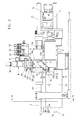
- the plastic injection molding unit supported on a table 12 can be moved in the direction of the sprue opening of an injection mold by means of at least one drive device A.
- the plasticizing cylinder 15 is received with its rear end in a central bore of a supply block 10.
- the pistons 13a of the drive device A designed as cylinders are fixed in the supply block 10.
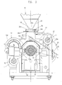
- Various supply devices can optionally be attached to the supply block 10 as supply unit B, W for supplying the plastic granulate. In the exemplary embodiment shown in the drawing, this is, on the one hand, a granulate container B (FIG. 1.3) and, on the other hand, a granule changer W (FIG. 2.4). All supply units B, W can be attached to the supply block 10 via the same connection elements.
- a carrier element which is designed as a base body 24 or support body 24 ', the supply unit B, W.
- the supply unit B, W is slidably arranged on a guide rail 18 which is fastened to a connection surface of the supply block 10.
- the Supply unit B, W can be set in different positions.
- the plastic material passes from the outlet opening 27a of the supply unit B, W via a supply bore 18a of the guide rail 18 into the chute 11 of the supply block 10 and into the plasticizing cylinder 15.
- outlet opening 27a and one cover one another Drain hole 18b In the emptying position (FIG. 8), outlet opening 27a and one cover one another Drain hole 18b.
- an injection device designed as an injection cylinder E is located on the injection molding unit for axially displacing the plasticizing screw 15a which is rotatably arranged in the plasticizing cylinder 15 via a rotary motor 16.
- the plasticizing cylinder 15 is covered by a protective housing 14 consisting of two housing halves 14 ', 14'.
- the guide rail 18 is arranged along and symmetrically to the vertical plane of symmetry a-a of the injection molding unit. It projects above a vertical end face 10c of the connection surface of the supply block 10 on the end face.
- the drain hole 18b is located in this projecting section approximately symmetrical to this plane of symmetry a-a.
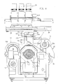
- the supply block 10 penetrated by two drive cylinders A and two injection cylinders E is guided for movement on the piston rods 13 of the drive cylinders A, which are symmetrical to the axis of the plasticizing cylinder 15.
- the emptying channel 23 is passed between a drive cylinder A and an injection cylinder E. In this case, circular punched edges 23a of the flanks 23b, 23c of the emptying channel bear against the lateral surface of the drive cylinder A.
- the stop surface 24b of the carrier element 24, 24 'of the supply unit B, W rests in the one end position in the supply position (FIG. 6) on a removable stop element 19 of the guide rail 18.
- the locking lever In order to get from the locked position under abutment of the stop surface 24a of the carrier element 24,24 'on the locking lug 20a of the locking lever into the emptying position, the locking lever must be moved against the force of a spring 22. The supply unit B, W can then be moved as far as it will go against the locking lug 20b of the locking lever 20. This ensures that the supply unit B, W is not inadvertently emptied. When leaving the emptying position ( Figure 8), the locking lever 20 returns to its starting position due to the spring force. In order to give the locking lever this possibility of movement, the guide rail 18 has a recess 18d.
- the carrier element is formed by the support body 24 'of a granulate changer W
- a displacement plate 29 driven by hydraulic drive cylinders H is fastened.
- the partly movable, partly stationary drive cylinders H are controlled by switching valves 33, 34.
- a further switching valve 32 controls a blocking slide via limit switches to cover the feed openings.
- Several feed hoses for different plastic materials are connected to the sliding plate 28 (FIG. 2).
- the feed hoses 30 of the granule changer are brought into congruence with the emptying bore 18b in the wake of a displacement perpendicular to one another.
- both carrier elements 24, 24 ' have stop surfaces 24a, 24b which are connected to the detents 20a, 20b or to the stop element 19.
- About guides 24c and 24d by wrap are the carrier elements 24, 24 'attached to the supply block 10.
- the carrier elements 24, 24 'differ in their geometric shape but have the same stop surfaces 24a, 24b, the same guide 24c and the same wrap around 24d.
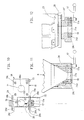
- the distance y-y between the injection pistons 36 protruding from the end face 10c of the supply block 10 and the adjacent drive cylinders A corresponds approximately to the clear width of the drain hole 18b.
- Drive cylinder A and injection cylinder E are symmetrical to planes f-f and e-e, which enclose an angle ⁇ of approximately 45 ° to one another (FIG. 3).
- the sliding surface 23d of the emptying channel 23 is at a distance from the adjacent injection piston 36, which just permits its free axial movement.
- the drain channel 23 is connected to the guide rail 18 by a screw 26.
- the connecting surface is formed by the horizontal surface of a rectangular shape 10a of a cuboid, central part 10e of the supply block 10, which has lateral wing areas 10d of low axial depth tt which accommodate the drive cylinders A and the injection cylinders E (FIG. 12).
- FIG. 9 shows the supply block 10 with the guide rail 18 attached, without a supply unit B, W being attached.
- the stop element 19 the locking lever 20 with its two locking lugs 20a, 20b, as well as the supply hole 18a and the drain hole 18b in the guide rail 18 can be clearly seen.
- the guide rail 18 is fastened to the supply block 10 with screws 18c.
Landscapes
- Engineering & Computer Science (AREA)
- Mechanical Engineering (AREA)
- Robotics (AREA)
- Manufacturing & Machinery (AREA)
- Injection Moulding Of Plastics Or The Like (AREA)
- Processing And Handling Of Plastics And Other Materials For Molding In General (AREA)
- Diaphragms For Electromechanical Transducers (AREA)
Abstract
Die Kunststoff-Spritzgießeinheit besitzt eine auf dem Versorgungsblock (10) angeordnete Versorgungseinheit (Granulatbehälter B), zur Zuführung des zu verarbeitenden Materials über einen Fallschacht (11) in den Plastifizierzylinder (15). Die Versorgungseinheit (B) ist dabei von einem Trägerelement (24) aufgenommen. Das Trägerelement (24) ist auf einer Führungsschiene (18) derart verschiebbar, daß die Versorgungseinheit (B) in einen Entleerkanal (23) entleerbar ist. Die Führungsschiene (18) ist längs der und symmetrisch zur vertikalen Symmetrieebene der Spritzgießeinheit angeordnet. Durch eine derartige Anordnung wird erreicht, daß bei weitgehend symmetrischem Aufbau der Schwerpunkt der Versorgungseinheit in Entleerungsposition in der vertikalen Symmetrieebene der Spritzgießeinheit liegt oder doch dieser wesentlich angenähert ist, wobei die Überführung der Versorgungseinheit (B) in Entleerposition annäherungsweise in der Symmetrieebene erfolgen kann. 
Description
Die Erfindung betrifft eine Kunststoff-Spritzgießeinheit entsprechend dem Oberbegriff des Anspruches 1.The invention relates to a plastic injection molding unit according to the preamble of
Bei den bekannten Spritzgießeinheiten dieser Art (DE 29 20 584 C2 - Fig. 4; DE 30 46 387 C2 - Sp. 2, Zn. 21-29 und Sp. 4, Zn. 20-30; DE 32 28 161) ist die Führungsschiene für die Versorgungseinheit derart quer zur oder neben der vertikalen Symmetrieebene der Spritzgießeinheit angeordnet, daß die Entleerungsbohrung außerhalb der vertikalen Projektionsfläche der Spritzgießeinheit liegt und somit für die Aufnahme des abrieselnden Kunststoff-Granulats ohne ohne weiteres zugänglich ist. Dieser Vorteil ist jedoch durch eine erhebliche Asymmetrie der Spritzgießeinheit oder ein starkes seitliches Ausladen der Versorgungseinheit bzw. Entleerungsvorrichtung erkauft. Dabei ist jede der in den genannten Druckschriften beschriebenen baulichen Konzeptionen einer Spritzgießeinheit notwendigerweise mit einer anderen räumlichen Anordnung der Führungsleiste im Verhältnis zur Symmetrieebene verknüpft.In the known injection molding units of this type (
In Übereinstimmung mit den gattungsgemäßen Spritzgießeinheiten ist es bei der Versorgungseinheit einer bekannten Strangpresse (DE-GM 71 48 839) möglich, die Auslauföffnung einer oder mehrerer Materialbehälter zur Deckung mit einer Entleerungsöffnung zu bringen, die sich im Abstand von der Symmetrieebene der Strangpresse befindet.In accordance with the generic injection molding units, it is possible in the supply unit of a known extrusion press (DE-GM 71 48 839) to cover the outlet opening of one or more material containers with an emptying opening which is at a distance from the plane of symmetry of the extrusion press.
Ausgehend von dem erörterten Stand der Technik liegt der Erfindung die Aufgabe zugrunde, eine Spritzgießeinheit der eingangs genannten Gattung derart weiterzubilden, daß eine rationelle Serienfertigung bei vereinfachter Lagerhaltung möglich ist, indem sie wahlweise mit unterschiedlichen Versorgungseinheiten betrieben werden kann, deren Schwerpunkt in Entleerungsposition in der vertikalen Symmetrieebene der Spritzgießeinheit liegt oder doch dieser wesentlich angenähert ist, und deren Überführung in Entleerungsposition auch bei sehr unterschiedlicher Gestaltung bzw. Anordnung von Versorgungsblock, Antriebszylindern und Einspritzzylindern annäherungsweise in der Symmetrieebene erfolgen kann. Diese Aufgabe wird erfindungsgemäß durch die im Kennzeichen des Patentanspruches 1 genannten Merkmale gelöst.Based on the prior art discussed, the invention has for its object to develop an injection molding unit of the type mentioned in such a way that an efficient series production with simplified storage is possible by it can be operated with different supply units, the focus of which is in the emptying position in the vertical Plane of symmetry of the injection molding unit is or this is substantially approximated, and its transfer into the emptying position can take place approximately in the plane of symmetry even with a very different design or arrangement of supply block, drive cylinders and injection cylinders. This object is achieved by the features mentioned in the characterizing part of
Die Lehre des Patentanspruches läßt sich bei Spritzgießeinheiten unterschiedlicher Bauart mit sehr unterschiedlichen Versorgungseinheiten verwirklichen. Sie ist besonders vorteilhaft bei stark seitlich ausladenden Versorgungsblöcken und hat zudem den wesentlichen Vorteil, daß nach dem Baukastenprinzip ein Granulatbehälter (vergl. DE 30 46 387 C2, Fig. 2) oder ein Granulatwechsler (vergl. DE 36 05 219 A1) auf der Führungsschiene in der Symmetrieebene führbar sind, soweit sie mit den gleichen Anschlußorganen versehen sind.The teaching of the claim can be realized in injection molding units of different designs with very different supply units. It is particularly advantageous in the case of supply blocks which protrude to the side and also has the essential advantage that a granulate container (see
Von besonderer Bedeutung ist die erfindungsgemäße Lösung bei Spritzgießeinheiten entsprechend der deutschen Patentanmeldung P 37 22 228, bei welchen diese aus einer zentralen Einspritzposition für eine zentrale Angußöffnung achsparallel in eine nicht zentrale Einspritzposition für eine nicht zentrale Angußöffnung verschoben werden kann.Denn bei diesen Spritzgießeinheiten wird verhindert, daß zu der durch die achsparallele Verschiebung der Spritzgießeinheit in eine nicht zentrale Position bedingten Asymmetrie eine zusätzliche weitere Asymmetrie durch das Verschieben der Verschiebeplatte des Granulatwechslers zu einer am freien Ende der Führungsschiene angeordneten Entleerungsöffnung kommt.The solution according to the invention is of particular importance in the case of injection molding units in accordance with German patent application P 37 22 228, in which they can be moved from a central injection position for a central sprue opening to a non-central injection position for a non-central sprue opening, since this prevents the injection units that to the asymmetry caused by the axially parallel displacement of the injection molding unit into a non-central position, an additional further asymmetry occurs by moving the displacement plate of the granule changer to an emptying opening arranged at the free end of the guide rail.
Bei einer Ausbildung des Versorgungsblockes entsprechend den Patentansprüchen 3 bis 6, kann die Führungsschiene extrem kurz gehalten werden, was bei Spritzgießeinheiten mit einer Einrichtung zum automatischen Wechseln des Plastifizierzylinders bei dessen Freisetzung und Abtransport von Bedeutung ist.When the supply block is designed in accordance with patent claims 3 to 6, the guide rail can be kept extremely short, which is important in injection molding units with a device for automatically changing the plasticizing cylinder when it is released and removed.
Nachstehend wird die Erfindung anhand der Zeichnungen erläutert.The invention is explained below with reference to the drawings.
Es zeigen:
- Fig. 1,2 die mit unterschiedlichen Versorgungseinheiten ausgerüstete Spritzgießeinheit in Seitenansicht,
- Fig. 3 die Spritzgießeinheit im Schnitt nach Linie III-III von Fig. 1 in vergrößerter Darstellung,
- Fig. 4 die Spritzgießeinheit im Schnitt nach Linie IV-IV von Fig. 2 in vergrößerter Darstellung,
- Fig. 5 die Spritzgießeinheit bei abgenommener Versorgungseinheit in Draufsicht,
- Fig. 6 die Führungsschiene mit angeschlossener Versorgungseinheit bei einem Schnitt nach Linie VI-VI von Fig. 1,
- Fign. 7 und 8 die Anordnung gemäß Fig. 6 bei anderen Positionen der Versorgungseinheit,
- Fig. 9 den Versorgungsblock mit seinen Antriebs- und Einspritzzylindern in perspektivischer Darstellung,
- Fig. 10 einen Schnitt nach Linie X-X von Fig. 4,
- Fig. 11 einen vergrößerten, teilgeschnittenen Ausschnitt von Fig. 3 und
- Fig. 12 einen vergrößerten, teilgeschnittenen Ausschnitt von Fig. 4.
- 1,2 the injection molding unit equipped with different supply units in a side view,
- 3 shows the injection molding unit in section along line III-III of FIG. 1 in an enlarged view,
- 4 shows the injection molding unit in section along line IV-IV of FIG. 2 in an enlarged view,
- 5 is a top view of the injection molding unit with the supply unit removed;
- 6 shows the guide rail with connected supply unit in a section along line VI-VI of FIG. 1,
- Fig. 7 and 8 the arrangement according to FIG. 6 in other positions of the supply unit,
- 9 the supply block with its drive and injection cylinders in a perspective view,
- 10 shows a section along line XX of FIG. 4,
- Fig. 11 is an enlarged, partially sectioned section of Fig. 3 and
- 12 is an enlarged, partially sectioned section of FIG. 4.
Die auf einem Tisch 12 abgestützte Kunststoff-Spritzgießeinheit ist mittels wenigstens einer Antriebseinrichtung A in Richtung der Angußöffnung einer Spritzgießform bewegbar. Der Plastifizierzylinder 15 ist dabei mit seinem rückwärtigen Ende in einer zentralen Bohrung eines Versorgungsblockes 10 aufgenommen. Die Kolben 13a der als Zylinder ausgebildeten Antriebseinrichtung A sind im Versorgungsblock 10 festgelegt. Auf dem Versorgungsblock 10 können als Versorgungseinheit B,W zur Zuführung des Kunststoffgranulats wahlweise verschiedene Zufuhreinrichtungen befestigt werden. Im zeichnerisch dargestellten Ausführungsbeispiel handelt es sich dabei zum einen um einen Granulatbehälter B (Figur 1,3), zum anderen um einen Granulatwechsler W (Figur 2,4). Alle Versorgungseinheiten B,W können über die gleichen Anschlußorgane am Versorgungsblock 10 befestigt werden. Dabei nimmt ein Trägerelement, das als Grundkörper 24 oder Tragkörper 24′ ausgebildet ist, die Versorgungseinheit B,W auf. Die Versorgungseinheit B,W ist auf einer Führungsschiene 18 verschiebbar angeordnet, die an einer Anschlußfläche des Versorgungsblockes 10 befestigt ist. Auf der Führungsschiene 18 kann die Versorgungseinheit B,W in verschiedenen Stellungen festgelegt werden. In Versorgungsposition (Figur 6) gelangt das Kunststoffmaterial aus der Auslauföffnung 27a der Versorgungseinheit B,W über eine Versorgungsbohrung 18a der Führungsschiene 18 in den Fallschacht 11 des Versorgungsblockes 10 und in den Plastifizierzylinder 15. In Entleerungsposition (Figur 8) decken sich Auslauföffnung 27a und eine Entleerungsbohrung 18b. Desweiteren befindet sich an der Spritzgießeinheit eine als Einspritzzylinder E ausgebildete Einspritzeinrichtung zur axialen Verschiebung der im Plastifizierzylinder 15 über einen Rotationsmotor 16 rotierbar angeordneten Plastifizierschnecke 15a. Der Plastifizierzylinder 15 ist durch ein aus zwei Gehäusehälften 14′,14˝ bestehendes Schutzgehäuse 14 abgedeckt.The plastic injection molding unit supported on a table 12 can be moved in the direction of the sprue opening of an injection mold by means of at least one drive device A. The plasticizing
Die Führungsschiene 18 ist längs der und symmetrisch zur vertikalen Symmetrieebene a-a der Spritzgießeinheit angeordnet. Dabei überragt sie eine vertikale Stirnfläche 10c der Anschlußfläche des Versorgungsblockes 10 stirnseitig. Die Entleerungsbohrung 18b befindet sich in diesem überragenden Abschnitt annäherungsweise symmetrisch zu dieser Symmetrieebene a-a. Quer zur Symmetrieebene a-a verläuft ein für ein Rutschgefälle ausreichend geneigter Entleerkanal 23, der am Versorgungsblock 10 mit einer vertikalen Flanke 23c anliegt. Sein Eingang befindet sich unter der Entleerungsbohrung 18b.The
Der von zwei Antriebszylinder A und zwei Einspritzzylindern E durchsetzte Versorgungsblock 10 ist zur Bewegung an den Kolbenstangen 13 der Antriebszylinder A geführt, die symmetrisch zur Achse des Plastifizierzylinders 15 liegen. Der Entleerkanal 23 ist zwischen einem Antriebszylinder A und einem Einspritzzylinder E hindurchgeführt. Dabei liegen kreisförmige Stanzkanten 23a der Flanken 23b,23c des Entleerkanals an der Mantelfläche des Antriebszylinders A an.The
Die Anschlagfläche 24b des Trägerelements 24,24′ der Versorgungseinheit B,W liegt in der einen Endposition in Versorgungsposition (Figur 6) an einem abnehmbaren Anschlagelement 19 der Führungsschiene 18 an. In der anderen Endposition in Entleerungsposition (Figur 8) sowie in einer mittleren Position in einer Sperrposition (Fig.7) liegt das Trägelement 24,24′ je an einer Rastnase 20b bzw. 20a eines in der Führungsschiene begrenzt um einen Schwenkbolzen 21 schwenkbaren Rasthebels 20 an. In diesen Stellungen ist das Trägerelement 24,24′ mittels eines Spannstückes 17a durch eine geringe Schwenkbewegung einer Spanneinrichtung 17 arretierbar. Um von der Sperrposition unter Anliegen der Anschlagfläche 24a des Trägerelementes 24,24′ an der Rastnase 20a des Rasthebels in die Entleerposition zu gelangen, muß der Rasthebel gegen die Kraft einer Feder 22 bewegt werden. Anschließend kann die Versorgungseinheit B,W bis zum Anschlag an der Rastnase 20b des Rasthebels 20 bewegt werden. Dadurch ist sichergestellt, daß kein unbeabsichtigtes Entleeren der Versorgungseinheit B,W stattfindet. Bei Verlassen der Entleerungsposition (Figur 8) geht der Rasthebel 20 infolge der Federkraft wieder in seine Ausgangsposition zurück. Um dem Rasthebel diese Bewegungsmöglichkeit zu geben, weist die Führungsschiene 18 eine Ausnehmung 18d auf. Ist das Trägerelement durch den Tragkörper 24′ eines Granulatwechslers W gebildet, so befindet sich auf dem Tragkörper 24′ senkrecht zur Symmetrieebene a-a eine Laufschiene 28. Auf dieser Laufschiene 28 ist über hydraulische Antriebszylinder H angetriebene Verschiebeplatte 29 befestigt. Die teils beweglichen, teils stationären Antriebszylinder H werden über Schaltventile 33,34 gesteuert. Ein weiteres Schaltventil 32 steuert über Endschalter dabei einen Sperrschieber zur Abdeckung der Zufuhröffnungen. An der Verschiebeplatte 28 sind mehrere Zuführschläuche für unterschiedliche Kunststoffmaterialien angeschlossen (Figur 2). Die Zufuhrschläuche 30 des Granulatwechslers werden im Gefolge senkrecht zueinander stehender Verschiebung mit der Entleerungsbohrung 18b zur Deckung gebracht.The
Durch Abnahme bzw. Anbringen des Anschlagelementes 19 an der Führungsschiene 18 können wahlweise der Grundkörper 24 des Granulatbehälters B oder der Tragkörper 24′ des Granulatwechslers W auf die Führungsschiene 18 aufgeschoben oder abgezogen werden. Beide Trägerelemente 24,24′ weisen dabei Anschlagflächen 24a,24b auf, die mit den Rastnasen 20a,20b oder mit dem Anschlagelement 19 in Verbindung stehen. Über Führungen 24c und durch Umgriff 24d sind die Trägerelemente 24,24′ am Versorgungsblock 10 befestigt. Wie durch Vergleich von Figur 8 und Figur 10 ersichtlich, unterscheiden sich die Trägerelemente 24,24′ zwar in ihrer geometrischen Form, besitzen jedoch die gleichen Anschlagflächen 24a,24b, die gleiche Führung 24c und den gleichen Umgriff 24d.By removing or attaching the
Der Abstand y-y zwischen den aus der Stirnfläche 10c des Versorgungsblockes 10 hervorragenden Einspritzkolbens 36 und den benachbarten Antriebszylindern A entspricht etwa der lichten Weite der Entleerungsbohrung 18b. Antriebszylinder A und Einspritzzylinder E liegen symmetrisch zu Ebenen f-f bzw. e-e, die einen Winkel α von etwa 45° zueinander einschließen (Figur 3).The distance y-y between the
Die Rutschfläche 23d des Entleerkanals 23 befindet sich in einem Abstand vom benachbarten Einspritzkolben 36, der dessen freie axiale Bewegung gerade noch zuläßt. Der Entleerkanal 23 ist durch eine Schraube 26 mit der Führungsschiene 18 verbunden.
Die Anschlußfläche wird durch die horizontale Oberfläche einer im Grundriß rechteckigen Ausformung 10a eines quaderförmigen, zentralen Teils 10e des Versorgungsblockes 10 gebildet, der seitliche, die Antriebszylinder A und die Einspritzzylinder E aufnehmende Flügelbereiche 10d geringer axialer Tiefe t-t aufweist (Figur 12).The sliding
The connecting surface is formed by the horizontal surface of a rectangular shape 10a of a cuboid,
Figur 9 zeigt den Versorgungsblock 10 mit angebrachter Führungsschiene 18, ohne daß eine Versorgungseinheit B,W aufgesetzt ist. Deutlich sind das Anschlagelement 19, der Rasthebel 20 mit seinen beiden Rastnasen 20a,20b, sowie die Versorgungsbohrung 18a und die Entleerungsbohrung 18b in der Führungsschiene 18 zu erkennen. Die Führungsschiene 18 ist mit Schrauben 18c am Versorgungsblock 10 befestigt.FIG. 9 shows the
Claims (7)
und daß der Entleerkanal (23) zwischen einem Antriebszylinder (A) und dem Einspritzzylinder (E) hindurchgeführt ist.3. Injection molding unit according to claim 1 or 2, characterized in that the supply block (10) which is penetrated by two drive cylinders (A) and two injection cylinders (E) is guided on the piston rods (13) of the drive cylinder, drive cylinder (A) and injection cylinder ( E) lie symmetrically to planes (ff; ee in FIG. 3) which enclose an angle (α) of approximately 45 ° to one another,
and that the emptying channel (23) is passed between a drive cylinder (A) and the injection cylinder (E).
Priority Applications (1)
| Application Number | Priority Date | Filing Date | Title |
|---|---|---|---|
| AT89110661T ATE90264T1 (en) | 1988-07-07 | 1989-06-13 | PLASTIC INJECTION MOLDING UNIT. |
Applications Claiming Priority (2)
| Application Number | Priority Date | Filing Date | Title |
|---|---|---|---|
| DE3822926A DE3822926A1 (en) | 1988-07-07 | 1988-07-07 | PLASTIC INJECTION MOLDING UNIT |
| DE3822926 | 1988-07-07 |
Publications (3)
| Publication Number | Publication Date |
|---|---|
| EP0349799A2 true EP0349799A2 (en) | 1990-01-10 |
| EP0349799A3 EP0349799A3 (en) | 1991-06-12 |
| EP0349799B1 EP0349799B1 (en) | 1993-06-09 |
Family
ID=6358106
Family Applications (1)
| Application Number | Title | Priority Date | Filing Date |
|---|---|---|---|
| EP89110661A Expired - Lifetime EP0349799B1 (en) | 1988-07-07 | 1989-06-13 | Plastic material injection-moulding unit |
Country Status (6)
| Country | Link |
|---|---|
| US (1) | US5022847A (en) |
| EP (1) | EP0349799B1 (en) |
| JP (1) | JPH0270413A (en) |
| AT (1) | ATE90264T1 (en) |
| CA (1) | CA1313933C (en) |
| DE (2) | DE3822926A1 (en) |
Cited By (2)
| Publication number | Priority date | Publication date | Assignee | Title |
|---|---|---|---|---|
| EP0888857A1 (en) * | 1997-07-02 | 1999-01-07 | Hartmut Vollmar | Device for feeding raw material in a plasticizer |
| WO2001089796A1 (en) * | 2000-05-24 | 2001-11-29 | Krauss-Maffei Kunststofftechnik Gmbh | Device and method for charging the plasticizing unit of an injection-moulding machine |
Families Citing this family (4)
| Publication number | Priority date | Publication date | Assignee | Title |
|---|---|---|---|---|
| DE4216312C1 (en) * | 1992-05-16 | 1993-11-25 | Karl Hehl | Plastic changing device |
| US5585122A (en) * | 1994-12-23 | 1996-12-17 | Reconversion Technologies, Inc. | Apparatus for converting raw materials into a molded end product |
| US6390661B1 (en) | 2000-09-15 | 2002-05-21 | Masco Corporation | Rapid discharge multiple material delivery system |
| WO2025096005A1 (en) | 2023-10-31 | 2025-05-08 | Moxietec, Llc | Shut-off nozzle for injection molding |
Family Cites Families (8)
| Publication number | Priority date | Publication date | Assignee | Title |
|---|---|---|---|---|
| DE7148839U (en) * | 1973-09-27 | Hagen R Gmbh | Extrusion press | |
| US4118168A (en) * | 1977-05-02 | 1978-10-03 | Husky Injection Molding Systems Limited | Guidance system for shallow articles discharged from a mold cavity |
| DE2920584C2 (en) * | 1979-05-21 | 1982-11-04 | Karl 7298 Loßburg Hehl | Arrangement of a plastic injection molding unit |
| AT372902B (en) * | 1978-11-04 | 1983-11-25 | Hehl Karl | DOUBLE-HOLE INJECTION MOLDING DEVICE |
| DE3046387C2 (en) * | 1980-12-09 | 1982-09-23 | Karl 7298 Loßburg Hehl | Injection molding unit of a plastic injection molding machine with a container for free-flowing plastic material |
| DE3228161C1 (en) * | 1982-07-28 | 1984-01-19 | Karl 7298 Loßburg Hehl | Feeding device for feeding plastic granulate into an injection molding unit |
| US4731005A (en) * | 1985-07-26 | 1988-03-15 | Karl Hehl | Injection molding unit for an injection molding machine |
| DE3722228A1 (en) * | 1987-05-11 | 1988-12-01 | Karl Hehl | PLASTIC INJECTION MOLDING MACHINE WITH AN INJECTABLE INJECTION MOLDING UNIT |
-
1988
- 1988-07-07 DE DE3822926A patent/DE3822926A1/en active Granted
-
1989
- 1989-06-13 EP EP89110661A patent/EP0349799B1/en not_active Expired - Lifetime
- 1989-06-13 AT AT89110661T patent/ATE90264T1/en not_active IP Right Cessation
- 1989-06-13 DE DE8989110661T patent/DE58904601D1/en not_active Expired - Fee Related
- 1989-06-14 CA CA000602794A patent/CA1313933C/en not_active Expired - Fee Related
- 1989-07-03 US US07/374,925 patent/US5022847A/en not_active Expired - Fee Related
- 1989-07-07 JP JP1174312A patent/JPH0270413A/en active Pending
Cited By (2)
| Publication number | Priority date | Publication date | Assignee | Title |
|---|---|---|---|---|
| EP0888857A1 (en) * | 1997-07-02 | 1999-01-07 | Hartmut Vollmar | Device for feeding raw material in a plasticizer |
| WO2001089796A1 (en) * | 2000-05-24 | 2001-11-29 | Krauss-Maffei Kunststofftechnik Gmbh | Device and method for charging the plasticizing unit of an injection-moulding machine |
Also Published As
| Publication number | Publication date |
|---|---|
| EP0349799B1 (en) | 1993-06-09 |
| DE3822926C2 (en) | 1991-05-16 |
| JPH0270413A (en) | 1990-03-09 |
| DE3822926A1 (en) | 1990-01-11 |
| DE58904601D1 (en) | 1993-07-15 |
| CA1313933C (en) | 1993-03-02 |
| EP0349799A3 (en) | 1991-06-12 |
| ATE90264T1 (en) | 1993-06-15 |
| US5022847A (en) | 1991-06-11 |
Similar Documents
| Publication | Publication Date | Title |
|---|---|---|
| CH656572A5 (en) | DEVICE FOR CHANGING THE INJECTION MOLD ON A PLASTIC INJECTION MOLDING MACHINE. | |
| DE3644709C2 (en) | ||
| EP0452270B1 (en) | Dispensing device using double cartridges | |
| EP0367950B1 (en) | Mixing device | |
| DE3046387C2 (en) | Injection molding unit of a plastic injection molding machine with a container for free-flowing plastic material | |
| EP0349799B1 (en) | Plastic material injection-moulding unit | |
| DE3530724C1 (en) | Dough dividing machine | |
| DE3242054C2 (en) | Transport device for an injection mold assigned to a mold clamping unit of a plastic injection molding machine | |
| EP0291008A2 (en) | Plastic injection-moulding machine with an injection unit movable into different working positions | |
| EP0578680B1 (en) | Slide bolt for melting pots | |
| EP0200962B1 (en) | Injection-unit for a plastics injection-moulded machine | |
| DE2504719A1 (en) | INJECTION MOLDING MACHINE | |
| DE2454402C2 (en) | Tube holder on textile machines for winding yarn or thread | |
| EP0483492B1 (en) | Stationary mould support for a plastic injection moulding machine | |
| DE3625074C2 (en) | ||
| DE2849145C3 (en) | Injection mold for transport boxes, in which the Formbachken can be moved on inclined guide pillars | |
| DE2325949C3 (en) | Threaded core for an injection molding supply for the production of a molded part provided with an internal thread | |
| EP0394790B1 (en) | Device for making a fluid reactive mixture from at least two fluid reactive components for making solid or cellular plastic material | |
| AT400022B (en) | Injection-moulding machine | |
| DE3021121C2 (en) | Device for placing and tensioning an endless belt of a spinning and twisting machine | |
| DE2112310C3 (en) | Injection molding machine with a mold clamping unit that can be attached to the machine base in either a horizontal or vertical position | |
| DE2753337B1 (en) | Injection mold for producing a can-shaped sharpener with an overmolded knife | |
| AT394969B (en) | INJECTION MOLDING MACHINE | |
| DE2715565A1 (en) | Clamping tool with rotating rod actuator - has moving and fixed clamp jaws and has guide rod surrounded by tilting disc | |
| DD219711A1 (en) | DEVICE FOR ASSEMBLING CYLINDRICAL COMPONENTS |
Legal Events
| Date | Code | Title | Description |
|---|---|---|---|
| PUAI | Public reference made under article 153(3) epc to a published international application that has entered the european phase |
Free format text: ORIGINAL CODE: 0009012 |
|
| AK | Designated contracting states |
Kind code of ref document: A2 Designated state(s): AT CH DE ES FR GB IT LI NL |
|
| PUAL | Search report despatched |
Free format text: ORIGINAL CODE: 0009013 |
|
| AK | Designated contracting states |
Kind code of ref document: A3 Designated state(s): AT CH DE ES FR GB IT LI NL |
|
| 17P | Request for examination filed |
Effective date: 19910507 |
|
| 17Q | First examination report despatched |
Effective date: 19921009 |
|
| GRAA | (expected) grant |
Free format text: ORIGINAL CODE: 0009210 |
|
| AK | Designated contracting states |
Kind code of ref document: B1 Designated state(s): AT CH DE ES FR GB IT LI NL |
|
| PG25 | Lapsed in a contracting state [announced via postgrant information from national office to epo] |
Ref country code: IT Free format text: LAPSE BECAUSE OF FAILURE TO SUBMIT A TRANSLATION OF THE DESCRIPTION OR TO PAY THE FEE WITHIN THE PRE;WARNING: LAPSES OF ITALIAN PATENTS WITH EFFECTIVE DATE BEFORE 2007 MAY HAVE OCCURRED AT ANY TIME BEFORE 2007. THE CORRECT EFFECTIVE DATE MAY BE DIFFERENT FROM THE ONE RECORDED.SCRIBED TIME-LIMIT Effective date: 19930609 Ref country code: GB Effective date: 19930609 Ref country code: FR Effective date: 19930609 Ref country code: ES Free format text: THE PATENT HAS BEEN ANNULLED BY A DECISION OF A NATIONAL AUTHORITY Effective date: 19930609 Ref country code: NL Effective date: 19930609 |
|
| REF | Corresponds to: |
Ref document number: 90264 Country of ref document: AT Date of ref document: 19930615 Kind code of ref document: T |
|
| REF | Corresponds to: |
Ref document number: 58904601 Country of ref document: DE Date of ref document: 19930715 |
|
| EN | Fr: translation not filed | ||
| NLV1 | Nl: lapsed or annulled due to failure to fulfill the requirements of art. 29p and 29m of the patents act | ||
| GBV | Gb: ep patent (uk) treated as always having been void in accordance with gb section 77(7)/1977 [no translation filed] |
Effective date: 19930609 |
|
| PLBE | No opposition filed within time limit |
Free format text: ORIGINAL CODE: 0009261 |
|
| STAA | Information on the status of an ep patent application or granted ep patent |
Free format text: STATUS: NO OPPOSITION FILED WITHIN TIME LIMIT |
|
| PGFP | Annual fee paid to national office [announced via postgrant information from national office to epo] |
Ref country code: DE Payment date: 19940511 Year of fee payment: 6 |
|
| 26N | No opposition filed | ||
| PGFP | Annual fee paid to national office [announced via postgrant information from national office to epo] |
Ref country code: AT Payment date: 19940620 Year of fee payment: 6 |
|
| PGFP | Annual fee paid to national office [announced via postgrant information from national office to epo] |
Ref country code: CH Payment date: 19940721 Year of fee payment: 6 |
|
| PG25 | Lapsed in a contracting state [announced via postgrant information from national office to epo] |
Ref country code: AT Effective date: 19950613 |
|
| PG25 | Lapsed in a contracting state [announced via postgrant information from national office to epo] |
Ref country code: CH Effective date: 19950630 Ref country code: LI Effective date: 19950630 |
|
| REG | Reference to a national code |
Ref country code: CH Ref legal event code: PL |
|
| PG25 | Lapsed in a contracting state [announced via postgrant information from national office to epo] |
Ref country code: DE Effective date: 19960301 |