EP0349701B1 - Device for displaying articles - Google Patents
Device for displaying articles Download PDFInfo
- Publication number
- EP0349701B1 EP0349701B1 EP88890300A EP88890300A EP0349701B1 EP 0349701 B1 EP0349701 B1 EP 0349701B1 EP 88890300 A EP88890300 A EP 88890300A EP 88890300 A EP88890300 A EP 88890300A EP 0349701 B1 EP0349701 B1 EP 0349701B1
- Authority
- EP
- European Patent Office
- Prior art keywords
- column
- carrier
- holding compartments
- merchandise
- carriers
- Prior art date
- Legal status (The legal status is an assumption and is not a legal conclusion. Google has not performed a legal analysis and makes no representation as to the accuracy of the status listed.)
- Expired - Lifetime
Links
- 239000000969 carrier Substances 0.000 claims abstract description 13
- 230000001747 exhibiting effect Effects 0.000 claims abstract 2
- 230000004308 accommodation Effects 0.000 claims 2
- 239000000463 material Substances 0.000 claims 1
- 229920003023 plastic Polymers 0.000 description 5
- 238000001746 injection moulding Methods 0.000 description 2
- 230000000007 visual effect Effects 0.000 description 1
Images


Classifications
-
- A—HUMAN NECESSITIES
- A47—FURNITURE; DOMESTIC ARTICLES OR APPLIANCES; COFFEE MILLS; SPICE MILLS; SUCTION CLEANERS IN GENERAL
- A47F—SPECIAL FURNITURE, FITTINGS, OR ACCESSORIES FOR SHOPS, STOREHOUSES, BARS, RESTAURANTS OR THE LIKE; PAYING COUNTERS
- A47F7/00—Show stands, hangers, or shelves, adapted for particular articles or materials
- A47F7/02—Show stands, hangers, or shelves, adapted for particular articles or materials for jewellery, dentures, watches, eye-glasses, lenses, or the like
- A47F7/022—Show stands, hangers, or shelves, adapted for particular articles or materials for jewellery, dentures, watches, eye-glasses, lenses, or the like for watches or for bracelets therefor
Definitions
- the invention relates to a device for displaying goods, in particular watch straps packed in boxes, with at least two, compartments for the goods having carriers and with a foot part, of which a column, which has a polygonal cross section and on which the carrier from the column projecting, protrudes upward, at least one undercut rib being provided on the supports, which rib is inserted into one of the slots provided on each side surface of the column.
- Devices for displaying goods are known in a wide variety of embodiments. Such devices, which are also called “sales stands", are used, for example, in e.g. to keep clear watch straps for sale in transparent plastic boxes. Such boxes are known from AT-B-292957, AT-B-348186 and AT-B-349684. An embodiment of such a plastic box has also become known through the publication of the Austrian brand No. 96780.
- DE-U-8701998 relates to a device for displaying goods packed in boxes (video cassettes) with a column which is rotatably mounted in an approximately C-shaped bracket attached to a wall. Undercut grooves are provided on each side surface of the column, which has a substantially square cross section, into which undercut ribs can be inserted on supports. Each carrier has an essentially L-shaped outline shape and has two compartments for the goods to be displayed. An actual foot part is not provided in the device according to DE-U-8701398.
- the compartments in the carriers of DE-U-8701398 are equipped with smooth side walls, each without grooves, which are essentially L-shaped.
- the invention has for its object to provide the simplest possible, from e.g. Specify in the injection molding process plastic parts assemblable device of the type mentioned, which has a form that attracts the attention of potential buyers.
- the carriers have an essentially rectangular outline shape and on one of their sides have an essentially triangular projection on which the at least one undercut rib is provided.
- the device according to the invention for displaying goods has a particularly striking shape due to its obliquely upward-pointing supports for the goods. It is nevertheless stable and composed of a few individual parts that are also simply shaped.
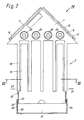
- a device shown in Figure 1 consists of a foot part 1, on which four carriers 2 for watch bands packed in boxes 3 are attached.
- the foot part 1 has in its center an upstanding column 4, which (see FIG. 6) is cuboid in the exemplary embodiment shown.
- a slot 5 tapering from top to bottom is provided.
- a connecting part 6 connecting the walls is provided.
- the foot part 1, including its column 4 and the connecting part 6, is preferably produced in one piece from plastic, for example by injection molding.
- the carriers 2 for the goods packed in boxes 3 are essentially rectangular in shape and have an approximately triangular extension 7 at one end.
- T-shaped ribs 9 and 10 are provided on the front faces 8 of the triangular extension 7.
- the webs 11 of the ribs 9 and 10 are of the same width over the entire length of the ribs.
- a cross piece 12 is provided at one end of each rib, which is approximately so long that it has little or no play in the wider end of the slot 5 of the column 4 on the foot part 1 sits when a support 2 has been attached to the column 4.
- the rib of the triangular projection 7 which is not fixed on the column 4 is received in a groove 36 which leads from the column 4 to the edge of the foot part 1 and is provided in the foot part 1.
- receiving compartments 15 for watch bands packed in plastic boxes 3 are provided in the rectangular part of the carrier 2.
- Grooves 16 are provided on the lateral boundary walls of the receiving compartments 15, which are open in the region of one side surface of the carrier 2 and towards its end remote from the triangular projection 7, into which the boxes 3 engage with their projecting edges 17.
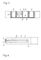
- one embodiment of the invention provides that inserts 18 can be used in the receiving compartments 15, which have a substantially U-shaped shape.
- the two longitudinal walls of the inserts 18 each have a rib 19 on the outside, which engages in one of the grooves 16 of the receiving compartments 15, as shown in FIG. 3.
- FIG. 2 also shows that in the triangular extension 7 of the carrier 2, a recess 20 is assigned to each of the four receiving compartments 15, into which inserts can be inserted which carry indications of the goods (watch straps) contained in the receiving compartments 15.
- a pivotable cover 21 is assigned to the ends of the supports 2 pointing away from the foot part 1.
- the pivot axis of the cover 21 relative to the carrier 2 is defined by pins 22 which engage in recesses 23 in the cover 21.
- the cover 21 In its closed position, the cover 21 is held on the side walls of the carrier 2 by wedge-shaped projections 26 which engage in the recesses 25 provided in its side walls 24.
- the lid 21 can only be opened again when the two side walls of the carrier 2 are pushed together somewhat in the region of the arrows 27 shown in FIG. 2.
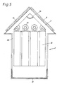
- the triangular extension 7 is hollow and on the outside of the rear wall 30 of the receiving compartments 15 a receiving space 31 is formed for a visual representation, which is delimited by a frame 32 which is connected to the carrier 2 is.
- a frame 32 which is connected to the carrier 2 is.
- an image or another advertising medium 33 can be inserted on each of the carriers 2.
- a support 34 projecting up to just below the frame 32 is provided.
- the device according to the invention can be placed as it is on a sales counter or the like. However, it is also possible to mount the device according to the invention rotatably on a lower part.
Landscapes
- Details Of Rigid Or Semi-Rigid Containers (AREA)
- Display Racks (AREA)
- Containers Having Bodies Formed In One Piece (AREA)
- Displays For Variable Information Using Movable Means (AREA)
Abstract
Description
Die Erfindung betrifft eine Vorrichtung zum Zurschaustellen von Waren, insbesondere von in Schachteln verpackten Uhrbändern, mit wenigstens zwei, Aufnahmefächer für die Waren aufweisenden Trägern und mit einem Fußteil, von dem eine Säule, die einen polygonalen Querschnitt aufweist und an der die Träger von der Säule abstehend festgelegt sind, nach oben ragt, wobei an den Trägern wenigstens eine hinterschnittene Rippe vorgesehen ist, die in einen der an jeder Seitenfläche der Säule vorgesehenen Schlitze eingesetzt ist.The invention relates to a device for displaying goods, in particular watch straps packed in boxes, with at least two, compartments for the goods having carriers and with a foot part, of which a column, which has a polygonal cross section and on which the carrier from the column projecting, protrudes upward, at least one undercut rib being provided on the supports, which rib is inserted into one of the slots provided on each side surface of the column.
Vorrichtungen zum Zurschaustellen von Waren sind in den verschiedensten Ausführungsformen bekannt. Derartige Vorrichtungen, die auch "Verkaufsständer" genannt werden, dienen beispielsweisse dazu, in z.B. durchsichtige Kunststoffschachteln verpackte Uhrbänder feilzuhalten. Derartige Schachteln sind aus der AT-B-292957, der AT-B-348186 und der AT-B-349684 bekannt. Eine Ausführungsform einer solchen Kunststoffschachtel ist auch durch die Veröffentlichung der österr. Marke Nr. 96780 bekannt geworden.Devices for displaying goods are known in a wide variety of embodiments. Such devices, which are also called "sales stands", are used, for example, in e.g. to keep clear watch straps for sale in transparent plastic boxes. Such boxes are known from AT-B-292957, AT-B-348186 and AT-B-349684. An embodiment of such a plastic box has also become known through the publication of the Austrian brand No. 96780.
Verkaufsständer für in Schachteln verpackte Uhrbänder sind aus den drei oben genannten österr. Patentschriften und zusätzlich aus der AT-B-249310 bekannt.Sales stands for watch bands packed in boxes are known from the three Austrian patents mentioned above and additionally from AT-B-249310.
Das DE-U-8701998 betrifft eine Vorrichtung zum Zurschaustellen von in Schachteln verpackten Waren (Videokassetten) mit einer Säule, die in einer etwa C-förmigen, an einer Wand befestigten Halterung verdrehbar gelagert ist. An jeder Seitenfläche der einen im wesentlichen quadratischen Querschnitt aufweisenden Säule sind hinterschnittene Nuten vorgesehen, in die hinterschnittene Rippen an Trägern eingeschoben werden können. Jeder Träger besitzt eine im wesentlichen L-förmige Umrißform und weist zwei Aufnahmefächer für die zur Schau zu stellenden Waren auf. Ein eigentlicher Fußteil ist bei der Vorrichtung gemnäß dem DE-U-8701398 nicht vorgesehen. Die Aufnahmefächer in den Trägern des DE-U-8701398 sind mit glatten, jeweils ohne Nuten ausgebildeten Seitenwänden, die im wesentlichen L-förmig sind, ausgestattet.DE-U-8701998 relates to a device for displaying goods packed in boxes (video cassettes) with a column which is rotatably mounted in an approximately C-shaped bracket attached to a wall. Undercut grooves are provided on each side surface of the column, which has a substantially square cross section, into which undercut ribs can be inserted on supports. Each carrier has an essentially L-shaped outline shape and has two compartments for the goods to be displayed. An actual foot part is not provided in the device according to DE-U-8701398. The compartments in the carriers of DE-U-8701398 are equipped with smooth side walls, each without grooves, which are essentially L-shaped.
Der Erfindung liegt die Aufgabe zugrunde, eine möglichst einfach aufgebaute, aus z.B. im Spritzgußverfahren herstellbaren Kunststoffteilen zusammensetzbare Vorrichtung der eingangs genannten Gattung anzugeben, die eine die Aufmerksamkeit von potentiellen Käufern anziehende Form besitzt.The invention has for its object to provide the simplest possible, from e.g. Specify in the injection molding process plastic parts assemblable device of the type mentioned, which has a form that attracts the attention of potential buyers.
Erfindungsgemäß wird diese Aufgabe dadurch gelöst, daß die Träger eine im wesentlichen rechteckförmige Umrißform besitzen und an einer ihrer Seiten einen im wesentlichen dreieckförmigen Ansatz besitzen, an dem die wenigstens eine hinterschnittene Rippe vorgesehen ist.According to the invention, this object is achieved in that the carriers have an essentially rectangular outline shape and on one of their sides have an essentially triangular projection on which the at least one undercut rib is provided.
Die erfindungsgemäße Vorrichtung zum Zurschaustellen von Waren besitzt durch ihre schräg nach oben weisenden Träger für die Ware eine besonders auffällige Form. Sie ist dennoch stabil und aus wenig Einzelteilen, die noch dazu einfach geformt sind, zusammengesetzt.The device according to the invention for displaying goods has a particularly striking shape due to its obliquely upward-pointing supports for the goods. It is nevertheless stable and composed of a few individual parts that are also simply shaped.
Weitere Einzelheiten und Merkmale der Erfindung ergeben sich aus den Unteransprüchen sowie der nachstehenden Beschreibung des in den Zeichnungen teilweise schematisch wiedergegebenen Ausführungsbeispieles. Es zeigt:
- Fig. 1 eine Vorrichtung in perspektivischer Darstellung,
Figur 2 einen Träger,Figur 3 einen Schnitt längs der Linie III-III inFigur 1,Figur 4 eine Ansicht eines Details gemäß Pfeil IV inFigur 2,Figur 5 einen Träger in Ansicht von der inFigur 2 hinten liegenden Seite,Figur 6 eine Draufsicht auf die erfindungsgemäße Vorrichtung undFigur 7 einen Schnitt längs der Linie VII-VII inFigur 6.
- 1 shows a device in perspective,
- FIG. 2 shows a carrier,
- FIG. 3 shows a section along the line III-III in FIG. 1,
- FIG. 4 shows a view of a detail according to arrow IV in FIG. 2,
- 5 shows a carrier in a view from the rear in FIG lying side,
- Figure 6 is a plan view of the device according to the invention and
- FIG. 7 shows a section along the line VII-VII in FIG. 6.
Eine in Figur 1 dargestellte Vorrichtung besteht aus einem Fußteil 1, an dem vier Träger 2 für in Schachteln 3 verpackte Uhrbänder befestigt sind.A device shown in Figure 1 consists of a
Wie aus Figur 7 ersichtlich, besitzt der Fußteil 1 in seiner Mitte eine nach oben ragende Säule 4, die (vgl. Figur 6) im gezeigten Ausführungsbeispiel quaderförmig ausgebildet ist. In jeder Seitenwand der Säule 4 ist ein sich von oben nach unten verjüngender Schlitz 5 vorgesehen. Um die Säule bzw. ihre Wände auch im oberen Endbereich der Säule 4 zusammenzuhalten, ist ein die Wände verbindender Verbindungsteil 6 vorgesehen. Vorzugsweise ist der Fußteil 1 einschließlich seiner Säule 4 und dem Verbindungsteil 6 einstückig aus Kunststoff beispielsweise im Spritzgußverfahren hergestellt.As can be seen from FIG. 7, the
Die Träger 2 für die in Schachteln 3 verpackten Waren sind im wesentlichen rechteckförmig ausgebildet und besitzen an einem Ende einen etwa dreieckförmigen Ansatz 7. An den vorderen Flächen 8 des dreieckförmigen Ansatzes 7 sind im Querschnitt T-förmige Rippen 9 und 10 vorgesehen. Die Stege 11 der Rippen 9 und 10 sind über die gesamte Länge der Rippen gleich breit ausgeführt. Um die Träger 2 an der Säule 4 des Fußteils 1 sicher festzuhalten, ist an einem Ende jeder Rippe ein Quersteg 12 vorgesehen, der etwa so lang ist, daß er mit keinem oder nur geringem Spiel im breiteren Ende des Schlitzes 5 der Säule 4 am Fußteil 1 sitzt, wenn ein Träger 2 an der Säule 4 befestigt worden ist. Die nicht an der Säule 4 festgelegte Rippe des dreieckförmigen Ansatzes 7 ist in einer von der Säule 4 zum Rand des Fußteils 1 führenden, im Fußteil 1 vorgesehenen Nut 36 aufgenommen.The
Im rechteckigen Teil des Trägers 2 sind im gezeigten Ausführungsbeispiel vier Aufnahmefächer 15 für in Kunststoffschachteln 3 verpackte Uhrbänder vorgesehen. An den seitlichen Begrenzungswänden der Aufnahmefächer 15, die im Bereich der einen Seitenfläche des Trägers 2 und zu dessen vom dreieckförmigen Ansatz 7 abgekehrten Ende hin offen ausgebildet sind, sind Nuten 16 vorgesehen, in welche die Schachteln 3 mit ihren vorspringenden Rändern 17 eingreifen.In the exemplary embodiment shown, four
Da für Damenuhrbänder schmälere Schachteln 3 verwendet werden, sieht eine Ausführungsform der Erfindung vor, daß in die Aufnahmefächer 15 Einsätze 18 eingesetzt werden können, die eine im wesentlichen U-förmige Gestalt besitzen. Die beiden Längswände der Einsätze 18 besitzen außen je eine Rippe 19, die in eine der Nuten 16 der Aufnahmefächer 15 eingreift, wie dies in Figur 3 gezeigt ist.Since
Figur 2 zeigt auch, daß im dreieckförmigen Ansatz 7 des Trägers 2 jedem der vier Aufnahmefächer 15 eine Aussparung 20 zugeordnet ist, in die Einsätze eingesetzt werden können, die Hinweise auf die in den Aufnahmefächern 15 enthaltenen Waren (Uhrbänder) tragen.FIG. 2 also shows that in the
Den vom Fußteil 1 wegweisenden Enden der Träger 2 ist ein verschwenkbarer Deckel 21 zugeordnet. Die Schwenkachse des Deckels 21 gegenüber dem Träger 2 wird durch Zapfen 22 definiert, die in Ausnehmungen 23 des Deckels 21 eingreifen. Der Deckel 21 wird in seiner Schließstellung durch in in seinen Seitenwangen 24 vorgesehene Vertiefungen 25 eingreifende keilförmige Vorsprünge 26 an den Seitenwänden des Trägers 2 festgehalten. Der Deckel 21 kann erst wieder geöffnet werden, wenn die beiden Seitenwände des Trägers 2 etwa im Bereich der in Figur 2 eingezeichneten Pfeile 27 etwas zusammengerückt werden. Somit ist sichergestellt, daß der Deckel 21 nicht ohne weiteres und für gewöhnlich nur unter Zuhilfenahme beider Hände geöffnet werden kann, so daß eine gewisse Diebstahlsicherung gegen das unbefugte Entfernen von Waren aus dem Träger 2 gewährleistet ist, da der Deckel 21 das Entfernen von Schachteln 3 aus einem der Aufnahmefächer 15 des Trägers 2 verhindert, wenn er geschlossen ist.A
Wie die Figur 3 und 5 zeigt, ist der dreieckförmige Ansatz 7 hohl ausgebildet und auf der Außenseite der Rückwand 30 der Aufnahmefächer 15 ist ein Aufnahmeraum 31 für eine bildliche Darstellung gebildet, der durch einen Rahmen 32, der mit dem Träger 2 verbunden ist, begrenzt ist. So kann, wie in Figur 1 gezeigt, an jedem der Träger 2 ein Bild oder ein sonstiger Werbeträger 33 eingeschoben werden. Um den Werbeträger 33 auch im Bereich des Hohlraums des dreieckförmigen Ansatzes 7 plan zu halten, ist eine bis knapp unter den Rahmen 32 ragende Abstützung 34 vorgesehen.As shown in FIGS. 3 and 5, the
Die erfindungsgemäße Vorrichtung kann wie sie ist auf einer Verkaufstheke od. dgl. aufgestellt werden. Es ist aber auch möglich, die erfindungsgemäße Vorrichtung auf einem Unterteil drehbar aufzusetzen.The device according to the invention can be placed as it is on a sales counter or the like. However, it is also possible to mount the device according to the invention rotatably on a lower part.
Aus Figur 1 ist noch ersichtlich, daß das obere Ende der Säule 4 durch eine pyramidenförmige Verschlußkappe 35 verschlossen ist.From Figure 1 it can still be seen that the upper end of the
Claims (18)
Priority Applications (1)
| Application Number | Priority Date | Filing Date | Title |
|---|---|---|---|
| AT88890300T ATE66120T1 (en) | 1988-07-04 | 1988-11-30 | DEVICE FOR DISPLAYING GOODS. |
Applications Claiming Priority (2)
| Application Number | Priority Date | Filing Date | Title |
|---|---|---|---|
| DE8808556U | 1988-07-04 | ||
| DE8808556U DE8808556U1 (en) | 1988-07-04 | 1988-07-04 | Device for displaying goods |
Publications (2)
| Publication Number | Publication Date |
|---|---|
| EP0349701A1 EP0349701A1 (en) | 1990-01-10 |
| EP0349701B1 true EP0349701B1 (en) | 1991-08-14 |
Family
ID=6825631
Family Applications (1)
| Application Number | Title | Priority Date | Filing Date |
|---|---|---|---|
| EP88890300A Expired - Lifetime EP0349701B1 (en) | 1988-07-04 | 1988-11-30 | Device for displaying articles |
Country Status (5)
| Country | Link |
|---|---|
| US (1) | US4921111A (en) |
| EP (1) | EP0349701B1 (en) |
| JP (1) | JPH0234112A (en) |
| AT (1) | ATE66120T1 (en) |
| DE (2) | DE8808556U1 (en) |
Family Cites Families (11)
| Publication number | Priority date | Publication date | Assignee | Title |
|---|---|---|---|---|
| AT96780B (en) * | 1923-10-16 | 1924-04-25 | Arpad Wabrouschek | Apparatus for producing photographs with a plastic effect. |
| AT249310B (en) * | 1963-10-14 | 1966-09-12 | Hans Hirsch & Soehne Leder Und | Device for holding for sale and dispensing stacked goods |
| BE759347Q (en) * | 1969-10-06 | 1971-04-30 | Hirsch Hans & Soehne | DISPENSER DISPENSER FOR STACKED ITEMS |
| US3993196A (en) * | 1975-08-28 | 1976-11-23 | Display Originals, Inc. | Turret for supporting box-dispensing units |
| DE7605360U1 (en) * | 1976-02-23 | 1977-08-11 | Fa. Reinhold Wauer, 7712 Blumberg | DISPLAY DISPLAY FOR WATCH STRAP PACKS |
| DE2639288B1 (en) * | 1976-09-01 | 1977-12-29 | Wauer Fa Reinhold | Sales displays, in particular for watch strap display packages |
| AT349684B (en) * | 1977-04-15 | 1979-04-25 | Hirsch Hermann Leder Kunstst | FILING AND DISPENSING DEVICE FOR GOODS |
| AT348186B (en) * | 1977-04-15 | 1979-02-12 | Hirsch Hermann Leder Kunstst | SALES STAND |
| US4247010A (en) * | 1978-08-07 | 1981-01-27 | Dlm, Inc. | Display stand and method of making same |
| DE8701998U1 (en) * | 1987-02-10 | 1987-06-11 | Fourkos, Napoleon, 8000 München | Presentation rack for video cassettes |
| US4767088A (en) * | 1987-07-07 | 1988-08-30 | Cardinal American Corporation | Multistation bird feeder support |
-
1988
- 1988-07-04 DE DE8808556U patent/DE8808556U1/en not_active Expired
- 1988-11-30 AT AT88890300T patent/ATE66120T1/en not_active IP Right Cessation
- 1988-11-30 EP EP88890300A patent/EP0349701B1/en not_active Expired - Lifetime
- 1988-11-30 DE DE8888890300T patent/DE3864258D1/en not_active Expired - Lifetime
- 1988-12-09 US US07/282,254 patent/US4921111A/en not_active Expired - Fee Related
- 1988-12-23 JP JP63325668A patent/JPH0234112A/en active Pending
Also Published As
| Publication number | Publication date |
|---|---|
| JPH0234112A (en) | 1990-02-05 |
| DE8808556U1 (en) | 1988-08-18 |
| ATE66120T1 (en) | 1991-08-15 |
| DE3864258D1 (en) | 1991-09-19 |
| EP0349701A1 (en) | 1990-01-10 |
| US4921111A (en) | 1990-05-01 |
Similar Documents
| Publication | Publication Date | Title |
|---|---|---|
| EP0120099B2 (en) | Display tray for merchandise | |
| EP0349701B1 (en) | Device for displaying articles | |
| EP0394891B1 (en) | Device for the display of goods | |
| DE69407947T2 (en) | Hanging device for long articles | |
| DE3026676C2 (en) | Component for stands for displaying goods, in particular packed in transparent sleeves | |
| DE3206669C2 (en) | Hanging cardboard | |
| DE69505579T2 (en) | Container with handle | |
| AT392620B (en) | ONE-PIECE CUTTING FOR A TRANSPORT AND SHOW PACKAGING FOR E.g. GOODS STORED IN BOXES | |
| DE19840812A1 (en) | Carton for transport and retail display of goods has retention slots for lid, minimizing risk of loss of lid following opening | |
| DE8812855U1 (en) | Display shipping box | |
| DE9306913U1 (en) | Sales stands | |
| DE3926171A1 (en) | SALES STAND | |
| DE29807289U1 (en) | Equipment for the presentation and hanging of goods | |
| DE9401713U1 (en) | container | |
| DE20219692U1 (en) | Shelving system for storage and display of goods, comprising specifically shaped boards with optional front door for insertion into space between them | |
| DE2709330A1 (en) | Transport and display container for Easter egg - has triangular egg holder insertable through openings in outer triangular section carton | |
| DE19651421A1 (en) | Packing for objects on sales stands | |
| DE29921986U1 (en) | Equipment for packaging, storage and presentation of objects ready for use | |
| DE8815390U1 (en) | Toolbox | |
| DE202008001738U1 (en) | Display device | |
| DE29609867U1 (en) | Equipment for the presentation and hanging of goods | |
| EP1449216A2 (en) | Receptacle for receiving a packaged data carrier | |
| DE7913158U1 (en) | Square-shaped sales container that can be produced from interrelated folding blanks | |
| DE8626786U1 (en) | Sales and storage packaging made of plastic | |
| DE3100356A1 (en) | Mobile system structure for receiving merchandise |
Legal Events
| Date | Code | Title | Description |
|---|---|---|---|
| PUAI | Public reference made under article 153(3) epc to a published international application that has entered the european phase |
Free format text: ORIGINAL CODE: 0009012 |
|
| AK | Designated contracting states |
Kind code of ref document: A1 Designated state(s): AT BE CH DE ES FR GB LI LU NL |
|
| 17P | Request for examination filed |
Effective date: 19891124 |
|
| RAP1 | Party data changed (applicant data changed or rights of an application transferred) |
Owner name: HIRSCH ARMBAENDER GESELLSCHAFT M.B.H. |
|
| 17Q | First examination report despatched |
Effective date: 19900515 |
|
| GRAA | (expected) grant |
Free format text: ORIGINAL CODE: 0009210 |
|
| AK | Designated contracting states |
Kind code of ref document: B1 Designated state(s): AT BE CH DE ES FR GB LI LU NL |
|
| PG25 | Lapsed in a contracting state [announced via postgrant information from national office to epo] |
Ref country code: NL Effective date: 19910814 Ref country code: ES Free format text: THE PATENT HAS BEEN ANNULLED BY A DECISION OF A NATIONAL AUTHORITY Effective date: 19910814 |
|
| REF | Corresponds to: |
Ref document number: 66120 Country of ref document: AT Date of ref document: 19910815 Kind code of ref document: T |
|
| REF | Corresponds to: |
Ref document number: 3864258 Country of ref document: DE Date of ref document: 19910919 |
|
| ET | Fr: translation filed | ||
| PG25 | Lapsed in a contracting state [announced via postgrant information from national office to epo] |
Ref country code: LU Free format text: LAPSE BECAUSE OF NON-PAYMENT OF DUE FEES Effective date: 19911130 |
|
| GBT | Gb: translation of ep patent filed (gb section 77(6)(a)/1977) | ||
| NLV1 | Nl: lapsed or annulled due to failure to fulfill the requirements of art. 29p and 29m of the patents act | ||
| PLBE | No opposition filed within time limit |
Free format text: ORIGINAL CODE: 0009261 |
|
| STAA | Information on the status of an ep patent application or granted ep patent |
Free format text: STATUS: NO OPPOSITION FILED WITHIN TIME LIMIT |
|
| 26N | No opposition filed | ||
| PGFP | Annual fee paid to national office [announced via postgrant information from national office to epo] |
Ref country code: FR Payment date: 19931029 Year of fee payment: 6 |
|
| PGFP | Annual fee paid to national office [announced via postgrant information from national office to epo] |
Ref country code: CH Payment date: 19931110 Year of fee payment: 6 |
|
| PGFP | Annual fee paid to national office [announced via postgrant information from national office to epo] |
Ref country code: GB Payment date: 19931125 Year of fee payment: 6 Ref country code: AT Payment date: 19931125 Year of fee payment: 6 |
|
| PGFP | Annual fee paid to national office [announced via postgrant information from national office to epo] |
Ref country code: BE Payment date: 19940125 Year of fee payment: 6 |
|
| PGFP | Annual fee paid to national office [announced via postgrant information from national office to epo] |
Ref country code: DE Payment date: 19940126 Year of fee payment: 6 |
|
| PG25 | Lapsed in a contracting state [announced via postgrant information from national office to epo] |
Ref country code: LI Effective date: 19941130 Ref country code: GB Effective date: 19941130 Ref country code: CH Effective date: 19941130 Ref country code: BE Effective date: 19941130 Ref country code: AT Effective date: 19941130 |
|
| BERE | Be: lapsed |
Owner name: HIRSCH ARMBANDER -G. M.B.H. Effective date: 19941130 |
|
| GBPC | Gb: european patent ceased through non-payment of renewal fee |
Effective date: 19941130 |
|
| PG25 | Lapsed in a contracting state [announced via postgrant information from national office to epo] |
Ref country code: FR Effective date: 19950731 |
|
| REG | Reference to a national code |
Ref country code: CH Ref legal event code: PL |
|
| PG25 | Lapsed in a contracting state [announced via postgrant information from national office to epo] |
Ref country code: DE Effective date: 19950801 |
|
| REG | Reference to a national code |
Ref country code: FR Ref legal event code: ST |