EP0349231A2 - Nuclear magnetic resonance flow-contrast angiography - Google Patents
Nuclear magnetic resonance flow-contrast angiography Download PDFInfo
- Publication number
- EP0349231A2 EP0349231A2 EP89306434A EP89306434A EP0349231A2 EP 0349231 A2 EP0349231 A2 EP 0349231A2 EP 89306434 A EP89306434 A EP 89306434A EP 89306434 A EP89306434 A EP 89306434A EP 0349231 A2 EP0349231 A2 EP 0349231A2
- Authority
- EP
- European Patent Office
- Prior art keywords
- volume
- gradient
- time
- phase
- flow
- Prior art date
- Legal status (The legal status is an assumption and is not a legal conclusion. Google has not performed a legal analysis and makes no representation as to the accuracy of the status listed.)
- Ceased
Links
Images


Classifications
-
- G—PHYSICS
- G01—MEASURING; TESTING
- G01R—MEASURING ELECTRIC VARIABLES; MEASURING MAGNETIC VARIABLES
- G01R33/00—Arrangements or instruments for measuring magnetic variables
- G01R33/20—Arrangements or instruments for measuring magnetic variables involving magnetic resonance
- G01R33/44—Arrangements or instruments for measuring magnetic variables involving magnetic resonance using nuclear magnetic resonance [NMR]
- G01R33/48—NMR imaging systems
- G01R33/54—Signal processing systems, e.g. using pulse sequences ; Generation or control of pulse sequences; Operator console
- G01R33/56—Image enhancement or correction, e.g. subtraction or averaging techniques, e.g. improvement of signal-to-noise ratio and resolution
- G01R33/563—Image enhancement or correction, e.g. subtraction or averaging techniques, e.g. improvement of signal-to-noise ratio and resolution of moving material, e.g. flow contrast angiography
Definitions
- the present invention relates to nuclear magnetic resonance (NMR) imaging and, more particularly, to a method of three-dimensional NMR flow-contrast angiographic imaging.
- NMR nuclear magnetic resonance
- Non-invasive NMR imaging techniques can be util strictlyized to detect flowing fluids, such as blood, in a sample, such as the human body, being analyzed.
- Techniques such as NMR angiography provide a selective means of fluid flow detection in blood vessels and the like, although the results do not always correlate well with other techniques, such as X-ray angiography, in measuring projected vessel anatomy, such as might be clinical useful in detecting atherosclerotic plaque. This lack of correlation appears to be due to the limited NMR image resolution caused by an inherently low signal-to-noise ratio, and flow effects which frequently cause artifactual loss of signal intensity.
- present NMR flow imaging techniques and particularly those techniques based upon phase effects, can provide important flow information, but only limited morphological information.
- Typical of the morphological information desired is the angiographic projection imaging of the bifurcations of the carotid arteries, which bifurcations are a frequent site of atheromatous plaque formation, which is itself a precursor of transient ischemic attack and stroke. It is therefore highly desirable to be able to image atherosclerotic plaque (especially prior to the ulcerization thereof, which may result in subintimal hemorrhage or brain emboli therefrom.
- a method for providing a three-dimensional nuclear magnetic resonance (NMR) flow-contrast angiograph of fluid flowing substantially only in a predetermined direction, with suppression of stationary material surrounding the fluid uses the steps of: acquiring a first set of image data from NMR responses generated from a volume-to-be-imaged by a three-dimensional volume imaging sequence preceded by a saturation portion saturing nuclear spins in a volume adjacent to, and in the direction from which the desired flow will enter, the volume-to-be-imaged; acquiring a second set of image data from other NMR responses generated by the same volume imaging sequence, but devoid of any preceding saturating portion; and subtracting one of the first and second data sets from the other to generated a difference data set from which a final image is displayed.
- a 3DFT volume imaging sequence is used, with flow-compensation used along both axes of phase encodation and along the axis used for frequency encodation.
- the first moment of all magnetic field gradient pulses, from volume selection time to echo time, on each of the separate three gradient axes, is nulled (i.e. set substantially equal to zero), with the total area (the amplitude-time integrated product) of the pulses being set substantially equal to zero along two of the three axes, and with the non-zero pulse area difference along one selected non-readout axis being balanced by a rewind gradient pulse after completion of the response signal readout. Nulling of higher order moments to compensate for higher order motion (acceleration, jerk, etc.) can be used, if needed.
- a sample 10 such as a living person and the like, to be imaged is situated in a substantially homogeneous static magnetic field B O directed in along the Z-axis of a Cartesian coordinate system, which, for convenience, is also the primary direction of flow, as shown by arrow A, of a liquid within a vessel 11, such as blood within the carotid artery and the like, in the sample.
- a vessel 11 such as blood within the carotid artery and the like
- nuclear spins are saturated in a first volume 12, displaced to one said of the volume 14 in which fluid flow is to be imaged; the direction of offset is that direction from which the fluid must flow to enter the image volume.
- the saturation is brought about, illustratively, by perturbation of the nuclei with a selective RF pulse (typically having the effect of rotating, or flipping, the nuclear spin axes by 60 o -120 o , and preferably by about 90 o , and hence will be shown as a selective pulse having a "flip" angle ⁇ ′ which is provided cotemporally with a magnetic field gradient to localize the magnetization M perturbation to volume 12. Thereafter, transverse magnetization spin phase coherence is destroyed, by a "spoiler" pulse and the like.
- the preferably 90 o RF pulse and associated magnetic field gradient signal pulses serve to saturate the nuclear spins contained in volume 12 by destroying all longitudinal magnetization and transverse spin coherence.
- the bounds of volume 12 are effectivley set by the amplitude and direction of the field gradient pulse used, and by the amplitude, shape and duration of the RF pulse.
- the saturated nuclei of the stationary material in volume 12 remain within volume 12, but the saturated nuclei of the flowing fluid move into image volume 14 and, when NMR response data is acquired from volume 14 responsive to a three-dimensional volume imaging technique, causes the signal from the flowing fluid (blood) in the vessel (carotid artery) 11 to be selectively decreased.
- the same volume 14 is again imaged with the same three-dimensional volume imaging technique, now devoid of the presaturation of nuclei in adjacent volume 12, and the new volume imaging data, in which arterial intensity has not been decreased, is subtracted from the image data obtained with presaturation, so that all responses from material in volume 14 into which the saturated spins have not been carried, from adjacent volume 12, are effectively cancelled; stationary tissues, vessels (veins) in which fluid flow occurs in a direction other than that of arrow A, and the like are effectivley suppressed, while vessels (arteries) with flow in direction A show up in high contrast.
- the suppression mode can be exchanged, so that fluid (venous blood) flow in another vessel 16 and in the opposite direction, as shown by arrow V, such as in the jugular vein, is contrasted, while stationary tissue and arterial flow (even in the carotid arteries) in the same imaged volume 14′, are effectively suppressed; the presaturated adjacent volume 18 is here offset from the imaged volume 14′ in the direction from which the flowing fluid will arrive into the volume 14′ to be imaged.
- the exchange of the lower adjacent volume 12, below the neck region 14 in which arterial flow is to be imaged, for upper adjacent volume 18, above the neck region in which venous flow is to be imaged can be accomplished by altering the shape of an associated RF pulse and/or the amplitude of the magnetic field gradient in the axial Z direction during presaturation, without movement of the NMR imaging equipment (not shown) or the patient therein. It will be seen that the flow in any direction can be imaged by the presaturation of a volume in the proper offset ralationship to the volume to be imaged. It will also be seen that simultaneous saturation of both volumes 12 and 18 can be used, prior to acquisition of image data, to provide simultanous detection of both arterial and venous structures.
- saturation of the two volumes 12 and 18 can be alternated so that a first data set, acquired with suppression in one direction, e.g. arterial suppression, is subtracted from a second data set acquired with suppression in the opposite direction, e.g. venous suppression, to yield a resulting response data set in which stationary material is not only suppressed, but also with fluid flow in opposite directions having opposite polarity, e.g. arterial and venous blood flows having equal intensity but being of opposite polarity, such that they can be color-coded by such polarity difference.
- Whether one or both adjacent volumes are presaturated there can also be a temporal interleaving of the acquisitions of response data from each portion of the total sample to be imaged; thus, a part of the total data set can be acquired, first with preceding saturation and then devoid of saturation, before another part of the data set is acquired.
- Figure 2 illustrates the time-coordinated gradient magnetic fields along the three Cartesian axis, i.e. the X-axis gradient magnetic field G X , the Y-axis gradient magnetic field G Y and the Z-axis gradient magnetic field G Z , along with the radio-frequency (RF) magnetic field, all applied to the sample to be investigated, in one presently preferred embodiment of the NMR imaging method of the present invention.
- RF radio-frequency
- Data for each three-dimensional volume image is obtained from the difference of first and second data sets; the first data set is obtained using a plurality N of repetitions of a first type fo the sequence of Figure 2, each of which first-type sequence contains an initial presaturation portion 21 and a transverse magnetization dephasing portion 23 prior to an imaging portion 25, and the second data set is obtained with an equal number N of repetitions of a second-type of sequence which is similar to the first type sequence in all respect but one, each second data set sequence is devoid of presaturation portion 21 and has only the dephasing and latter imaging portion 25.
- Each presaturation portion 21 serves to selectiveivelyly saturate a volume 12 or 18 of material, prior to flow of some of that material into the image volume 14 of interest.
- a radio-frequency (RF) pulse signal 27 is applied in the presence of a gradient magnetic field pulse 29, to rotate the transverse magnetization spins of the sample through a flip angle ⁇ ′ of between about 60° and about 120°, with an excitation angle of 90° being preferable. This transverse magnetization rotation reduces the longitudinal magnetization of the fluid in that portion of the fluid vessel upstream of the image volume of interest.
- Presaturation portion 21 occupies the time interval from time t0 to time t4; a gradient magnetic field in the direction defining the limits of the presaturated volume (here the Z-axis direction) commences with an initial portion 29a, beginnning at time t0, when the gradient magnetic field G Z changes from a substantially zero amplitude towards the final amplitude.
- the RF pulse commences, reaching a peak at a later time t2 (which time can be considered to be the time at which the RF pulse acts substantially in its entirety), and terminates at a slightly later time t3;
- the RF pulse can be of any desirable shape, such as a truncated sinc(x) form, limiting the presaturation-excited region to predetermine limits in the Z direction.
- the RF pulse 27 is complexly modulated by a further cosine factor, serving to determine the degree of offset of the center region 12 from the center of region 14.
- the presaturation portion ends, in portion 29c, with the return to a substantially zero amplitude of the gradient G Z at time t4.
- a pulse d3e1 of the same or different gradient magnetic field (here, the Z-direction field G Z ) occurs between time t5 and time t6, with amplitude-time energy sufficient to dephase any transverse magnetization created by the presaturation operation in portion 21.
- data is acquired from the volume 14 containing the vessels of interest, by use of any desired 3D imaging sequence with a low-flip-angle ⁇ RF pulse 33.
- a gradient-refocussed 3D Fourier transform (3DFT) portion 25 The 3DFT portion is repeated the plurality N of times, where N is the product of M stripes in each of L planes making up the total volume.
- Each portion 25 starts with the RF pulse 33, having the relatively low flip angle ⁇ typically in the range from about 20° to about 40°, with a preferred flip angle ⁇ of about 30°; the rotation of spins is established in the desired volume remaining orthogonal gradient, i.e.
- the gradient magnetic fields in the Y and Z directions are varied through the N combinations of M values of one gradient, say G Y , and L values of the other gradient, say G Z , in manner well-known to the art.
- Flow compensation is applied to the two phase-encoding axes (Y and Z) to reduce flow artifacts in the phase-encoding directions.
- the bipolar phase-encoding lobes 45 and 47 in the Y-axis magnetic field gradient G Y occur for each pair of amplitudes selected to phase-encode one Y-direction "stripe", with all of a plurality of Y-stripes being encoded in one of a larger plurality of sequence repetitions for each of the first and second data sets.
- the G Y gradient which was at a substantially zero amplitude in initial portion 44, is thus set ot be at a first polarity (e.g.
- Y-axis phase-encoding thus consists of lobe 45 and lobe 47, with opposite polarity; a corresponding velocity-compensation is determined by the first moment of the gradient lobes, with respect to the data acquisition interval center time t E .
- Y-axis flow compensated lobe 45 commences at time t f and ens at time t j , when lobe 47 commences.
- the amplitude-time integration product A Y1 of flow-compensated lobe 45 is somewhat less than the amplitude-time area A Y2 of lobe 47 (which appears to act at a time t e which is at a time interval T Y2 from echo time t1).
- the Z-axis phase-encoding lobes 40 and 42 occur.
- the amplitude-time area A Z4 of lobe 40 and the area A Z5 of lobe 42 are selected such that the sum of the areas is equivalent to the area of a hypothetical phase-encoding pulse which is not flow-compensated.
- the Z gradient falls to a substantially zero level in portion 43, after time t n .
- a Z1 +A Z2 +A Z3 0
- Z-axis phase encodation can be made insensitive to higher orders of motion (i.e. acceleration, jerk, etc.) by extending the number of pulses and selecting amplitudes and durations to null the corresponding higher order (i.e. second, third, etc.) moment.
- the readout direction X magnetic field gradient G X is a pulse 51 having a desired value during the readout time interval, from time t n to time t q (substantially symmetrical about the echo time t E ). Only the first portion of the readout X-gradient pulse 51, from time t n to time t E is considered for balancing of G X areas and moments. We have found that such balancing is best facilitated by use of a pulse lobe 53 having the same polarity (e.g. positive) as the readout gradient pulse 51, and counterbalanced by a pulse 55 of opposite polarity.
- the X-axis magnetic field gradient begins with a first-polarity (e.g.
- the amplitude of all thre X-axis gradient pulses 51, 53 and 55 may be made equal, and only the polarity and time duration varied (although such a single amplitude condition need not obtain, as indicated by the different amplitudes of the G X pulses 50, 53 and 55 illustrated).
- the initial dephasing X-axis pulse portion 55a begins at time t g and ends at time t k , has an area A X2 and a first moment M X2 proportional to the time interval T X2 , from t i to echo time t E ; the latter dephasing pulse portion 55b occurs between t k and time t n , with an area A X3 and a first moment M X3 proportional to that area and the moment time interval T X3 from latter pulse portion center time t m to echo time t E .
- the initial gradient readout portion 51a from time t n to echo time t E , has an area A X4 , which appears to act at time t p and generates a moment M X4 proportional to that area and time interval T X4 , from time t p to time t E .
- the X-axis magnetic field gradient G X thus has a substantially zero value in portion 57, prior to first lobe 53, and in latter portion 59, after time t q , when the latter portion 51b of the readout gradient returns substantially to zero amplitude.
- phase-encoding higher order of motion can be compensated for with more complex waveshapes in the X-axis gradient signal.
- a first phase-encoding direction rewind pulse 61 is provided after each readout; the pulse 61 has a duration from time t r to time t s , and an amplitude chosen such that the total amplitude-time integral is a quantity ⁇ A Y which is equal to the inverse of the sum of the Y-axis gradient flow-compensated phase-encoding lobe 47 (area A Y2 ) and lobe 45 (area A Y1 ).
- phase-encoding lobes 40 and 42 and lobes 45 and 47 may occur in essentially the same time intervals, for simultaneous phase-encoding and flow-compensation in both directions
- the third axis (here, the X-axis magnetic field gradient G X ) need not have the pulses 53 and 55, compensating the area and first moment of the readout pulse initial portion 51a, coincident with any of the pulses of the other two gradient magnetic fields.
- pulse 53 starting time t c need only be after the RF pulse 33 completion time t9, while pulse 55b need end not later than the readout pulse 51 start time t n .
- phase-encoded flow artifacts are reduced by shaping the gradient pulses to focus the echoes from both stationary and flowing material at the echo time T E when the NMR response signal is acquired, and that constant flow velocity artifacts are eliminated by nulling the gradient first moments with respect to the echo time, so that Nulling higher order terms appears to give a negligible improvement in image quality, and, while acceleration compensation can be accomplished by shaping the gradient pulses to null second-moment terms, however, we have found that second-moment nulling procedures increase the acquisition time.
- FIG. 3A an angiograph of the neck area of a human volunteer subject is shown.
- the image data set which ideally contains information from only arterial blood, was formed by the subtraction of voxel information from first and second image data sets, each containing an image reconstructed separately from one of the first data set (with the presaturation pulses 27 and 29) and the second data set (devoid of pulses 27 and 29 prior to imaging sequence 25).
- the angiograph of the 46-year old male volunteer shows a pronounced crescent-shaped area 64 and a considerably smaller crescent-shaped area 65 the posterior aspect of the left internal carotid artery. Both show reduced vessel cross-section and appear to indicate the presence of plaque.
- FIG. 3B The angiographic findings were verified with a pair of axial slice images, shown in Figure 3B.
- the first slice shown in the upper half of the image, was taken in a plane cutting though the larger crescent-shaped region 64; a crescent-shaped region 67 of narrowing is shown in the bifurcated left carotid artery, while the single right carotid artery lumen 68 is substantially circular (being encountered slightly below the bifurcation thereof).
- the bottom half of Figure 3b is another axial slice image taken in a plane slightly above the image in the plane of the top portion of this Figure, and clearly shows both bifurcated carotid arteries, with substantially circular lumens of all four branches.
- stenosis of the internal carotid artery is seen to appear as a vertical groove in region 64 and 67, on the distal posterior surface of the right carotid artery.
- the source of flow signal shown as a decreased intensity
- commencement of plaque formation and growth in the posterior lateral aspect of the carotid sinus is frequently encountered and well known, and usually attributed to the hemodynamics which reduce the chemical transport in this region of low shear flow.
- the stenosis regions seen in Figure 3A imaged by utilized of the modulated presaturation method of the present invention, may be missed in angiographic imaging, unless the view direction catches the stenosis in profile.
- use of the method of the present invention especially with construction of a gradient-shaded three-dimensional image formed by surface following techniques, provides a sensitive method for detecting surface roughness, among other diagnostic and scientific uses.
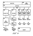
- FIG. 4 is a simplified block diagram of the major components of an NMR system suitable for use with the NMR pulse sequences of the invention described herein.
- the system generally designated 400, comprises a general purpose minicomputer 401 which is functionally coupled to disk storage unit 403 and in Interface unti 405.
- An RF transmitter 402, signal averager 404, and gradient power supplies 406, 408, and 410 for energizing, respectively, G x , G y , G z , gradient coils 416, 418, and 420, are coupled to computer 401 through interface unit 405.
- RF transmitter 402 is gated with pulse envelopes from computer 401 to generate RF pulses having the required modulation to excite resonance in the object under study.
- the RF pulses are amplified in RF power amplifier 412 to levels varying from 100 watts to several kilowatts, depending on the NMR method, and applied to transmitter coil 424. The higher power levels are necessary for large sample volumes, and where short duration pulses are required to excite large NMR frequency bandwidths.
- the NMR signal is sensed by received coil 426, amplified in a low noise preamplifier 422, and applied for further amplification, detection, and filtering to receiver 414.
- the signal is then digitized for averaging by signal averager 404 and for processing by computer 401.
- Preamplifier 422 and receiver 414 are protected from the RF pulses during transmission by active gating or by passive filtering.
- Computer 401 provides gating and envelope modulation for the NMR pulses, blanking for the preamplifier and RF power amplified, voltage waveforms for the gradient power supplies and advances gradient amplitudes, and the frequency of RF pulses (when frequency scanning is employed).
- the computer also performs data processing such as Fourier transforms, image reconstruction, data filtering, imaging display, and storage functions (all of which are operations conventionally performed by minicomputers and hence described only functionally, supra).
- the transmitter and receiver RF coils may comprise a single coil.
- two separate coils tha t are electrically orthogonal may be used.
- the latter configuration has the advantage of reduced RF pulse breakthrough into the receiver during pulse transmission.
- the fields of coils are orthogonal to the direction of the static magnetic field B O produced by magnet 428.
- the coils are isolated from the remainder of the system by enclosure in the RF-shielded cage.
Abstract
Description
- The present invention relates to nuclear magnetic resonance (NMR) imaging and, more particularly, to a method of three-dimensional NMR flow-contrast angiographic imaging.
- Non-invasive NMR imaging techniques can be utilized to detect flowing fluids, such as blood, in a sample, such as the human body, being analyzed. Techniques such as NMR angiography provide a selective means of fluid flow detection in blood vessels and the like, although the results do not always correlate well with other techniques, such as X-ray angiography, in measuring projected vessel anatomy, such as might be clinical useful in detecting atherosclerotic plaque. This lack of correlation appears to be due to the limited NMR image resolution caused by an inherently low signal-to-noise ratio, and flow effects which frequently cause artifactual loss of signal intensity. Thus, present NMR flow imaging techniques, and particularly those techniques based upon phase effects, can provide important flow information, but only limited morphological information. Typical of the morphological information desired is the angiographic projection imaging of the bifurcations of the carotid arteries, which bifurcations are a frequent site of atheromatous plaque formation, which is itself a precursor of transient ischemic attack and stroke. It is therefore highly desirable to be able to image atherosclerotic plaque (especially prior to the ulcerization thereof, which may result in subintimal hemorrhage or brain emboli therefrom. The presence of smooth atherosclerotic plaque, causing hemodynamically significant stenosis, is presently clinically evaluated with a standard X-ray dye angiographic procedure, in which clinical evaluation of carotid artery disease requires injection of a contrast dye, via a catheter, in an invasive test which is not totally benign. It is therefore highly desirable to use a non-invasive magnetic resonance technique which provides a display in which only the arterial blood flow appears, with the stationary surrounding tissue and the blood flow in the adjacent veins being effectively suppressed.
- In accordance with the invention, a method for providing a three-dimensional nuclear magnetic resonance (NMR) flow-contrast angiograph of fluid flowing substantially only in a predetermined direction, with suppression of stationary material surrounding the fluid, uses the steps of: acquiring a first set of image data from NMR responses generated from a volume-to-be-imaged by a three-dimensional volume imaging sequence preceded by a saturation portion saturing nuclear spins in a volume adjacent to, and in the direction from which the desired flow will enter, the volume-to-be-imaged; acquiring a second set of image data from other NMR responses generated by the same volume imaging sequence, but devoid of any preceding saturating portion; and subtracting one of the first and second data sets from the other to generated a difference data set from which a final image is displayed. Advantageously, a 3DFT volume imaging sequence is used, with flow-compensation used along both axes of phase encodation and along the axis used for frequency encodation.
- In a presently preferred pulse sequence for three-dimensional NMR flow-contrast angiography, the first moment of all magnetic field gradient pulses, from volume selection time to echo time, on each of the separate three gradient axes, is nulled (i.e. set substantially equal to zero), with the total area (the amplitude-time integrated product) of the pulses being set substantially equal to zero along two of the three axes, and with the non-zero pulse area difference along one selected non-readout axis being balanced by a rewind gradient pulse after completion of the response signal readout. Nulling of higher order moments to compensate for higher order motion (acceleration, jerk, etc.) can be used, if needed.
- A better understanding of the present invention will become apparent upon reading of the following illustrative description, when considered in conjunction with the drawings in which:
- Figure 1A is a side view of a portion of a human subject, and of the region thereof to be imaged, and useful in appreciating several features of the present invention;
- Figure 1B is another side view of a human subject, illustrating the manner in which emphasis of venous blood flow, with rejection of arterial flow, is achieved, and also useful in understanding several features of the present invention;
- Figure 2 is a set of time-coordinated gradient and radio-frequency (RF) signal waveforms used in one presently preferred embodiment of the imaging procedure of the present invention;
- Figure 3A is a photograph of an angiographic display of the carotid artery bifurcations of a volunteer subject, illustrating acquisition of atherosclerotic plaque information;
- Figure 3B is a pair of axial NMR slice images, in planes dictated by the angiographic flow data of Figure 3A, and useful for comparison purposes; and
- Figure 4 illustrates a simplified block diagrtam of the major components of an NMR imaging apparatus for practicing the invention.
- Refering initially to Figure 1A, a
sample 10, such as a living person and the like, to be imaged is situated in a substantially homogeneous static magnetic field BO directed in along the Z-axis of a Cartesian coordinate system, which, for convenience, is also the primary direction of flow, as shown by arrow A, of a liquid within a vessel 11, such as blood within the carotid artery and the like, in the sample. As a first step in our novel method, nuclear spins are saturated in afirst volume 12, displaced to one said of thevolume 14 in which fluid flow is to be imaged; the direction of offset is that direction from which the fluid must flow to enter the image volume. The saturation is brought about, illustratively, by perturbation of the nuclei with a selective RF pulse (typically having the effect of rotating, or flipping, the nuclear spin axes by 60o-120o, and preferably by about 90o, and hence will be shown as a selective pulse having a "flip" angle α′ which is provided cotemporally with a magnetic field gradient to localize the magnetization M perturbation tovolume 12. Thereafter, transverse magnetization spin phase coherence is destroyed, by a "spoiler" pulse and the like. Thus, the preferably 90o RF pulse and associated magnetic field gradient signal pulses serve to saturate the nuclear spins contained involume 12 by destroying all longitudinal magnetization and transverse spin coherence. The bounds ofvolume 12 are effectivley set by the amplitude and direction of the field gradient pulse used, and by the amplitude, shape and duration of the RF pulse. The saturated nuclei of the stationary material involume 12 remain withinvolume 12, but the saturated nuclei of the flowing fluid move intoimage volume 14 and, when NMR response data is acquired fromvolume 14 responsive to a three-dimensional volume imaging technique, causes the signal from the flowing fluid (blood) in the vessel (carotid artery) 11 to be selectively decreased. After a time sufficient to allow the nuclei in the fluid to recover from saturation, thesame volume 14 is again imaged with the same three-dimensional volume imaging technique, now devoid of the presaturation of nuclei inadjacent volume 12, and the new volume imaging data, in which arterial intensity has not been decreased, is subtracted from the image data obtained with presaturation, so that all responses from material involume 14 into which the saturated spins have not been carried, fromadjacent volume 12, are effectively cancelled; stationary tissues, vessels (veins) in which fluid flow occurs in a direction other than that of arrow A, and the like are effectivley suppressed, while vessels (arteries) with flow in direction A show up in high contrast. - Referring now to Figure 1B, the suppression mode can be exchanged, so that fluid (venous blood) flow in another
vessel 16 and in the opposite direction, as shown by arrow V, such as in the jugular vein, is contrasted, while stationary tissue and arterial flow (even in the carotid arteries) in the same imagedvolume 14′, are effectively suppressed; the presaturatedadjacent volume 18 is here offset from theimaged volume 14′ in the direction from which the flowing fluid will arrive into thevolume 14′ to be imaged. The exchange of the loweradjacent volume 12, below theneck region 14 in which arterial flow is to be imaged, for upperadjacent volume 18, above the neck region in which venous flow is to be imaged, can be accomplished by altering the shape of an associated RF pulse and/or the amplitude of the magnetic field gradient in the axial Z direction during presaturation, without movement of the NMR imaging equipment (not shown) or the patient therein. It will be seen that the flow in any direction can be imaged by the presaturation of a volume in the proper offset ralationship to the volume to be imaged. It will also be seen that simultaneous saturation of bothvolumes volumes - Figure 2 illustrates the time-coordinated gradient magnetic fields along the three Cartesian axis, i.e. the X-axis gradient magnetic field GX, the Y-axis gradient magnetic field GY and the Z-axis gradient magnetic field GZ, along with the radio-frequency (RF) magnetic field, all applied to the sample to be investigated, in one presently preferred embodiment of the NMR imaging method of the present invention. Data for each three-dimensional volume image is obtained from the difference of first and second data sets; the first data set is obtained using a plurality N of repetitions of a first type fo the sequence of Figure 2, each of which first-type sequence contains an
initial presaturation portion 21 and a transverse magnetization dephasingportion 23 prior to animaging portion 25, and the second data set is obtained with an equal number N of repetitions of a second-type of sequence which is similar to the first type sequence in all respect but one, each second data set sequence is devoid ofpresaturation portion 21 and has only the dephasing andlatter imaging portion 25. - Each
presaturation portion 21 serves to selectively saturate avolume image volume 14 of interest. A radio-frequency (RF) pulse signal 27 is applied in the presence of a gradientmagnetic field pulse 29, to rotate the transverse magnetization spins of the sample through a flip angle α′ of between about 60° and about 120°, with an excitation angle of 90° being preferable. This transverse magnetization rotation reduces the longitudinal magnetization of the fluid in that portion of the fluid vessel upstream of the image volume of interest.Presaturation portion 21 occupies the time interval from time t₀ to time t₄; a gradient magnetic field in the direction defining the limits of the presaturated volume (here the Z-axis direction) commences with an initial portion 29a, beginnning at time t₀, when the gradient magnetic field GZ changes from a substantially zero amplitude towards the final amplitude. Once the substantially constant portion 29b commences, at time t₁, the RF pulse commences, reaching a peak at a later time t₂ (which time can be considered to be the time at which the RF pulse acts substantially in its entirety), and terminates at a slightly later time t₃; the RF pulse can be of any desirable shape, such as a truncated sinc(x) form, limiting the presaturation-excited region to predetermine limits in the Z direction. Here, the RF pulse 27 is complexly modulated by a further cosine factor, serving to determine the degree of offset of thecenter region 12 from the center ofregion 14. The presaturation portion ends, in portion 29c, with the return to a substantially zero amplitude of the gradient GZ at time t₄. - In the transverse magnetization dephasing, or "spoiler",
portion 23, a pulse d3e1 of the same or different gradient magnetic field (here, the Z-direction field GZ) occurs between time t₅ and time t₆, with amplitude-time energy sufficient to dephase any transverse magnetization created by the presaturation operation inportion 21. - Now, data is acquired from the
volume 14 containing the vessels of interest, by use of any desired 3D imaging sequence with a low-flip-angleα RF pulse 33. We illustratively use a gradient-refocussed 3D Fourier transform (3DFT)portion 25. The 3DFT portion is repeated the plurality N of times, where N is the product of M stripes in each of L planes making up the total volume. Eachportion 25 starts with theRF pulse 33, having the relatively low flip angle α typically in the range from about 20° to about 40°, with a preferred flip angle α of about 30°; the rotation of spins is established in the desired volume remaining orthogonal gradient, i.e. gradient GX in the X direction in this example, is utilized as the readout gradient. Thus, the gradient magnetic fields in the Y and Z directions are varied through the N combinations of M values of one gradient, say GY, and L values of the other gradient, say GZ, in manner well-known to the art. - Flow compensation is applied to the two phase-encoding axes (Y and Z) to reduce flow artifacts in the phase-encoding directions. In the illustrated example, the bipolar phase-
encoding lobes 45 and 47 in the Y-axis magnetic field gradient GY occur for each pair of amplitudes selected to phase-encode one Y-direction "stripe", with all of a plurality of Y-stripes being encoded in one of a larger plurality of sequence repetitions for each of the first and second data sets. The GY gradient, which was at a substantially zero amplitude ininitial portion 44, is thus set ot be at a first polarity (e.g. a positive polarity) and a first amplitude (e.g. here, the maximum phase-encoding Y-direction amplitude) in the Y phase-encoding portion 47, from time tj to time tn. The Y-axis phase-encoding thus consists of lobe 45 andlobe 47, with opposite polarity; a corresponding velocity-compensation is determined by the first moment of the gradient lobes, with respect to the data acquisition interval center time tE. Y-axis flow compensated lobe 45 commences at time tf and ens at time tj, whenlobe 47 commences. The amplitude-time integration product AY1 of flow-compensated lobe 45 is somewhat less than the amplitude-time area AY2 of lobe 47 (which appears to act at a time te which is at a time interval TY2 from echo time t₁). A first desirable condition is that the first moments in the Y direction be nulled, i.e. add substantially to zero, so that
MY2+MY1=0 (1a)
or
AY2·TY2+AY1·TY1=0. (1b)
This condition reduces, and (if equality is reached) can remove, the velocity-induced phase shifts caused by phase-encoding gradient pulses 45 and 47. Higher orders of motion are readily compensated for by use of more complex waveforms with higher order moments summed to zero (i.e. acceleration-induced shifts compensated for by nulling of second moment, etc.) - During the same time interval, from time tf to time tn, the Z-axis phase-encoding
lobes 40 and 42 occur. The amplitude-time area AZ4 of lobe 40 and the area AZ5 oflobe 42 are selected such that the sum of the areas is equivalent to the area of a hypothetical phase-encoding pulse which is not flow-compensated. The Z gradient falls to a substantially zero level inportion 43, after time tn. Another desired condition on the Z-axis gradient lobes is that the sum of the slice select areas is nulled:
AZ1+AZ2+AZ3=0 (2)
the other desired condition is the nulling of the total first-moments, with:
MZ1+MZ2+MZ3+MZ4+MZ5=0 (3a)
or,
AZ1·TZ1+AZ2·TZ2+AZ3·TZ3+AZ4·TZ4+AZ5·TZ5=0 (3b)
where TZ1 is the time interval from t₈ to TE, TZ2 is the time interval from ta to tE,TZ3 is the time interval from td to tE, TZ4 is the time interval from th to TE, and TZ5 is the time interval from tℓ to TE. As with the Y-axis phase-encoding pulses, Z-axis phase encodation can be made insensitive to higher orders of motion (i.e. acceleration, jerk, etc.) by extending the number of pulses and selecting amplitudes and durations to null the corresponding higher order (i.e. second, third, etc.) moment. - The readout direction X magnetic field gradient GX is a
pulse 51 having a desired value during the readout time interval, from time tn to time tq (substantially symmetrical about the echo time tE). Only the first portion of the readoutX-gradient pulse 51, from time tn to time tE is considered for balancing of GX areas and moments. We have found that such balancing is best facilitated by use of apulse lobe 53 having the same polarity (e.g. positive) as thereadout gradient pulse 51, and counterbalanced by a pulse 55 of opposite polarity. Thus, the X-axis magnetic field gradient begins with a first-polarity (e.g. positive)pulse signal 53, from a time tc to a time tg, having an amplitude-time integral area AX1, and having a first-moment appearing to act at pulse center time te, at a time interval TX1 from echo time tE. Thereafter, the dephasing X-axis gradient pulse 55 occurs, from time tg to time tn; for ease of nulling the areas and first moments in the X-axis magnetic field gradient, gradient pulse 55 is split into first andsecond portions 55a and 55b, with a separation time tk. For purposes of convenience, the amplitude of all threX-axis gradient pulses dephasing pulse portion 55b occurs between tk and time tn, with an area AX3 and a first moment MX3 proportional to that area and the moment time interval TX3 from latter pulse portion center time tm to echo time tE. The initial gradient readout portion 51a, from time tn to echo time tE, has an area AX4, which appears to act at time tp and generates a moment MX4 proportional to that area and time interval TX4, from time tp to time tE. The X-axis magnetic field gradient GX thus has a substantially zero value inportion 57, prior tofirst lobe 53, and inlatter portion 59, after time tq, when the latter portion 51b of the readout gradient returns substantially to zero amplitude. In accordance with principles of the invention, the summation of the X-axis gradient areas is nulled, so that
AX1+AX2+AX3+AX4=0 (4)
and the summation of the first X-gradient moment is also nulled, so that
MX1+MX2+MX3+MX4=0 (5)
where MX1=AX1·TX1, MX2=AX2·TX2, MX3=AX3·TX3 and MX4=AX4·TX4.
As with phase-encoding, higher order of motion can be compensated for with more complex waveshapes in the X-axis gradient signal. - In accordance with another principle of the present invention, a first phase-encoding
direction rewind pulse 61 is provided after each readout; thepulse 61 has a duration from time tr to time ts, and an amplitude chosen such that the total amplitude-time integral is a quantity ΔAY which is equal to the inverse of the sum of the Y-axis gradient flow-compensated phase-encoding lobe 47 (area AY2) and lobe 45 (area AY1). Thus, the sum of the Y-axis magnetic field gradient GY areas is nulled, for each repetition of the imaging sequence, so that
AY2+AY1+ΔAY=0 (6)
If desird, the first repetition of the entire sequence can be preceded by a first phase-encoding-axis rewind pulse 61′, of amplitude and time duration established as above. - It will be seen that, while phase-
encoding lobes 40 and 42 andlobes 45 and 47 may occur in essentially the same time intervals, for simultaneous phase-encoding and flow-compensation in both directions, the third axis (here, the X-axis magnetic field gradient GX) need not have thepulses 53 and 55, compensating the area and first moment of the readout pulse initial portion 51a, coincident with any of the pulses of the other two gradient magnetic fields. Thus,pulse 53 starting time tc need only be after theRF pulse 33 completion time t₉, whilepulse 55b need end not later than thereadout pulse 51 start time tn. - It will be understood that phase-encoded flow artifacts are reduced by shaping the gradient pulses to focus the echoes from both stationary and flowing material at the echo time TE when the NMR response signal is acquired, and that constant flow velocity artifacts are eliminated by nulling the gradient first moments with respect to the echo time, so that

- Referring now to Figure 3A, an angiograph of the neck area of a human volunteer subject is shown. The image data set, which ideally contains information from only arterial blood, was formed by the subtraction of voxel information from first and second image data sets, each containing an image reconstructed separately from one of the first data set (with the presaturation pulses 27 and 29) and the second data set (devoid of
pulses 27 and 29 prior to imaging sequence 25). The angiograph of the 46-year old male volunteer shows a pronounced crescent-shapedarea 64 and a considerably smaller crescent-shaped area 65 the posterior aspect of the left internal carotid artery. Both show reduced vessel cross-section and appear to indicate the presence of plaque. The angiographic findings were verified with a pair of axial slice images, shown in Figure 3B. The first slice, shown in the upper half of the image, was taken in a plane cutting though the larger crescent-shapedregion 64; a crescent-shapedregion 67 of narrowing is shown in the bifurcated left carotid artery, while the single rightcarotid artery lumen 68 is substantially circular (being encountered slightly below the bifurcation thereof). The bottom half of Figure 3b is another axial slice image taken in a plane slightly above the image in the plane of the top portion of this Figure, and clearly shows both bifurcated carotid arteries, with substantially circular lumens of all four branches. Thus, stenosis of the internal carotid artery is seen to appear as a vertical groove inregion - Figure 4 is a simplified block diagram of the major components of an NMR system suitable for use with the NMR pulse sequences of the invention described herein. The system, generally designated 400, comprises a
general purpose minicomputer 401 which is functionally coupled todisk storage unit 403 and inInterface unti 405. AnRF transmitter 402, signalaverager 404, andgradient power supplies computer 401 throughinterface unit 405. -
RF transmitter 402 is gated with pulse envelopes fromcomputer 401 to generate RF pulses having the required modulation to excite resonance in the object under study. The RF pulses are amplified inRF power amplifier 412 to levels varying from 100 watts to several kilowatts, depending on the NMR method, and applied totransmitter coil 424. The higher power levels are necessary for large sample volumes, and where short duration pulses are required to excite large NMR frequency bandwidths. - The NMR signal is sensed by received
coil 426, amplified in alow noise preamplifier 422, and applied for further amplification, detection, and filtering toreceiver 414. The signal is then digitized for averaging bysignal averager 404 and for processing bycomputer 401.Preamplifier 422 andreceiver 414 are protected from the RF pulses during transmission by active gating or by passive filtering. -
Computer 401 provides gating and envelope modulation for the NMR pulses, blanking for the preamplifier and RF power amplified, voltage waveforms for the gradient power supplies and advances gradient amplitudes, and the frequency of RF pulses (when frequency scanning is employed). The computer also performs data processing such as Fourier transforms, image reconstruction, data filtering, imaging display, and storage functions (all of which are operations conventionally performed by minicomputers and hence described only functionally, supra). - The transmitter and receiver RF coils, if desird, may comprise a single coil. Alternatively, two separate coils tha t are electrically orthogonal may be used. The latter configuration has the advantage of reduced RF pulse breakthrough into the receiver during pulse transmission. In both cases, the fields of coils are orthogonal to the direction of the static magnetic field BO produced by
magnet 428. The coils are isolated from the remainder of the system by enclosure in the RF-shielded cage.
Claims (28)
Applications Claiming Priority (2)
| Application Number | Priority Date | Filing Date | Title |
|---|---|---|---|
| US07/211,612 US4849697A (en) | 1988-06-27 | 1988-06-27 | Three-dimensional magnetic resonance flow-contrast angiography with suppression of stationary material |
| US211612 | 1988-06-27 |
Publications (2)
| Publication Number | Publication Date |
|---|---|
| EP0349231A2 true EP0349231A2 (en) | 1990-01-03 |
| EP0349231A3 EP0349231A3 (en) | 1990-12-12 |
Family
ID=22787649
Family Applications (1)
| Application Number | Title | Priority Date | Filing Date |
|---|---|---|---|
| EP19890306434 Ceased EP0349231A3 (en) | 1988-06-27 | 1989-06-26 | Nuclear magnetic resonance flow-contrast angiography |
Country Status (3)
| Country | Link |
|---|---|
| US (1) | US4849697A (en) |
| EP (1) | EP0349231A3 (en) |
| JP (1) | JPH0263437A (en) |
Cited By (1)
| Publication number | Priority date | Publication date | Assignee | Title |
|---|---|---|---|---|
| EP0371477A2 (en) * | 1988-11-30 | 1990-06-06 | Hitachi, Ltd. | Magnetic resonance imaging method for moving object |
Families Citing this family (30)
| Publication number | Priority date | Publication date | Assignee | Title |
|---|---|---|---|---|
| US4978918A (en) * | 1988-04-24 | 1990-12-18 | Mitsubishi Denki Kabushiki Kaisha | Magnetic resonance imaging method |
| DE4004185C2 (en) * | 1989-02-24 | 1997-08-07 | Siemens Ag | Process for obtaining flux-compensated, T¶2¶-weighted images by means of nuclear magnetic resonance |
| DE4018683A1 (en) * | 1989-06-23 | 1991-01-10 | Siemens Ag | LAYERING PROFILE OPTIMIZATION FOR A NUCLEAR SPIN TOMOGRAPHER USED WITH A GRADIENT ECHOSE SEQUENCE |
| US4973906A (en) * | 1989-08-17 | 1990-11-27 | General Electric Company | Flow compensated NMR fast pulse sequence |
| US4994744A (en) * | 1989-10-27 | 1991-02-19 | General Electric Company | Method for combining acquired NMR data to suppress motion artifacts |
| US5034694A (en) * | 1989-11-22 | 1991-07-23 | Picker International, Inc. | Minimum basis set MR angiography |
| US5190744A (en) * | 1990-03-09 | 1993-03-02 | Salutar | Methods for detecting blood perfusion variations by magnetic resonance imaging |
| US6994841B1 (en) * | 1990-03-09 | 2006-02-07 | Kucharczyk And Moseley Partners | Relating to magnetic resonance imaging |
| EP0447970B1 (en) * | 1990-03-20 | 1997-09-10 | Kabushiki Kaisha Toshiba | Method and apparatus for imaging blood vessels employing magnetic resonance |
| US5221898A (en) * | 1990-11-30 | 1993-06-22 | Hitachi, Ltd. | Flow imaging method using an MRI apparatus |
| US5133357A (en) * | 1991-02-07 | 1992-07-28 | General Electric Company | Quantitative measurement of blood flow using cylindrically localized fourier velocity encoding |
| US5225779A (en) * | 1991-08-28 | 1993-07-06 | Ihc Hospitals, Inc. | Hybrid magnetic aresonance spatial and velocity imaging |
| US5273040A (en) * | 1991-11-14 | 1993-12-28 | Picker International, Inc. | Measurement of vetricle volumes with cardiac MRI |
| US5315248A (en) * | 1992-03-02 | 1994-05-24 | Kabushiki Kaisha Toshiba | Method and apparatus for nuclear magnetic resonance for measuring speed of flowing target object |
| US5554929A (en) * | 1993-03-12 | 1996-09-10 | Doty Scientific, Inc. | Crescent gradient coils |
| US5530355A (en) * | 1993-05-13 | 1996-06-25 | Doty Scientific, Inc. | Solenoidal, octopolar, transverse gradient coils |
| EP0628836B1 (en) * | 1993-06-02 | 1998-09-09 | Koninklijke Philips Electronics N.V. | Device and a method for magnetic resonance imaging |
| DE4337503C1 (en) * | 1993-11-03 | 1995-02-09 | Siemens Ag | Method for spatially resolved blood-flow measurement by means of nuclear magnetic resonance |
| US5410248A (en) * | 1993-12-29 | 1995-04-25 | General Electric Company | Method for the simultaneous detection of velocity and acceleration distribution in moving fluids |
| US5436562A (en) * | 1993-12-29 | 1995-07-25 | General Electric Company | Methods for the simultaneous detection of multiple components of motion in moving fluids |
| US5469059A (en) * | 1993-12-30 | 1995-11-21 | General Electric Company | Method for the simultaneous detection of acceleration and velocity distribution in moving fluids |
| US5517116A (en) * | 1993-12-30 | 1996-05-14 | General Electric Company | Method for the simultaneous detection of multiple components of velocity in moving fluids |
| US5846197A (en) * | 1998-03-16 | 1998-12-08 | Beth Israel Deaconess Medical Center | Compensating for magnetization transfer effects in multislice and three-dimensional MRI blood flow mapping studies |
| US6377832B1 (en) * | 1998-03-20 | 2002-04-23 | Georgia Tech Research Corporation | System and method for analyzing a medical image |
| JP4357641B2 (en) * | 1999-06-29 | 2009-11-04 | 株式会社東芝 | MRI equipment |
| WO2002071020A1 (en) * | 2001-03-03 | 2002-09-12 | Hogahm Technology Co. Ltd | Proximity sensor system having proximity sensor with bipolar signal output |
| JP3891799B2 (en) * | 2001-06-21 | 2007-03-14 | ジーイー・メディカル・システムズ・グローバル・テクノロジー・カンパニー・エルエルシー | MRI equipment |
| DE102007006142A1 (en) * | 2007-02-07 | 2008-08-14 | Siemens Ag | Method and apparatus for automatically determining a flow of body fluid within vessels of a living being |
| WO2011034004A1 (en) * | 2009-09-17 | 2011-03-24 | 株式会社 日立メディコ | Magnetic resonance imaging device and method for applying a gradient magnetic field |
| JP6073661B2 (en) * | 2012-11-21 | 2017-02-01 | 株式会社日立製作所 | Magnetic resonance imaging apparatus and magnetic resonance imaging method |
Citations (3)
| Publication number | Priority date | Publication date | Assignee | Title |
|---|---|---|---|---|
| EP0082684A2 (en) * | 1981-12-21 | 1983-06-29 | Albert Macovski | Blood vessel projection imaging system using nuclear magnetic resonance |
| EP0126381A1 (en) * | 1983-05-18 | 1984-11-28 | General Electric Company | An NMR method for measuring and imaging fluid flow |
| EP0234526A2 (en) * | 1986-02-25 | 1987-09-02 | Spectrospin AG | NMR imaging method for the determination of flowing materials |
Family Cites Families (8)
| Publication number | Priority date | Publication date | Assignee | Title |
|---|---|---|---|---|
| US4565968A (en) * | 1983-02-16 | 1986-01-21 | Albert Macovski | Blood vessel projection imaging system using nuclear magnetic resonance |
| US4609872A (en) * | 1984-08-10 | 1986-09-02 | General Electric Company | NMR multiple-echo phase-contrast blood flow imaging |
| US4777957A (en) * | 1985-06-14 | 1988-10-18 | General Electric Company | Method for measuring and imaging fluid flow |
| US4752734A (en) * | 1985-08-06 | 1988-06-21 | The General Hospital Corporation | Flow imaging by means of nuclear magnetic resonance |
| US4714081A (en) * | 1986-03-03 | 1987-12-22 | General Electric Company | Methods for NMR angiography |
| US4718424A (en) * | 1986-08-07 | 1988-01-12 | Stanford University | NMR imaging of blood flow by moment variation of magnetic gradients |
| US4716367A (en) * | 1986-08-15 | 1987-12-29 | Brigham & Women's Hospital | Creation and use of a moving reference frame for NMR imaging of flow |
| DE3627750A1 (en) * | 1986-08-16 | 1988-02-18 | Spectrospin Ag | METHOD FOR DETERMINING MOVABLE MATERIAL WITHIN A BODY |
-
1988
- 1988-06-27 US US07/211,612 patent/US4849697A/en not_active Expired - Lifetime
-
1989
- 1989-06-20 JP JP1156000A patent/JPH0263437A/en active Granted
- 1989-06-26 EP EP19890306434 patent/EP0349231A3/en not_active Ceased
Patent Citations (3)
| Publication number | Priority date | Publication date | Assignee | Title |
|---|---|---|---|---|
| EP0082684A2 (en) * | 1981-12-21 | 1983-06-29 | Albert Macovski | Blood vessel projection imaging system using nuclear magnetic resonance |
| EP0126381A1 (en) * | 1983-05-18 | 1984-11-28 | General Electric Company | An NMR method for measuring and imaging fluid flow |
| EP0234526A2 (en) * | 1986-02-25 | 1987-09-02 | Spectrospin AG | NMR imaging method for the determination of flowing materials |
Non-Patent Citations (3)
| Title |
|---|
| BOOK OF ABSTRACTS OF THE 7TH ANNUAL MEETING AND EXHIBITION, SOCIETY OF MAGNETIC RESONANCE IN MEDICINE * |
| IEEE TRANSACTIONS ON MEDICAL IMAGING * |
| MAGNETIC RESONANCE IN MEDICINE * |
Cited By (3)
| Publication number | Priority date | Publication date | Assignee | Title |
|---|---|---|---|---|
| EP0371477A2 (en) * | 1988-11-30 | 1990-06-06 | Hitachi, Ltd. | Magnetic resonance imaging method for moving object |
| EP0371477A3 (en) * | 1988-11-30 | 1991-10-23 | Hitachi, Ltd. | Magnetic resonance imaging method for moving object |
| US5115812A (en) * | 1988-11-30 | 1992-05-26 | Hitachi, Ltd. | Magnetic resonance imaging method for moving object |
Also Published As
| Publication number | Publication date |
|---|---|
| JPH0263437A (en) | 1990-03-02 |
| EP0349231A3 (en) | 1990-12-12 |
| US4849697A (en) | 1989-07-18 |
| JPH0426852B2 (en) | 1992-05-08 |
Similar Documents
| Publication | Publication Date | Title |
|---|---|---|
| EP0349231A2 (en) | Nuclear magnetic resonance flow-contrast angiography | |
| US6094591A (en) | Measurement of coronary flow reserve with MR oximetry | |
| US4516582A (en) | NMR blood flow imaging | |
| JP4011585B2 (en) | MRI system | |
| EP1444530B1 (en) | Three-dimensional phase contrast magnetic resonance imaging using interleaved projection-reconstruction data | |
| US6377834B1 (en) | Real time in vivo measurement of temperature changes with contrast enhanced NMR imaging | |
| US6442414B1 (en) | Magnetic resonance imaging apparatus | |
| EP1145029B1 (en) | Contrast guided reconstruction in contrast-enhanced magnetic resonance angiography | |
| US5711300A (en) | Real time in vivo measurement of temperature changes with NMR imaging | |
| EP1223433B1 (en) | Method and apparatus using post contrast-enhanced steady-state free precession in MR imaging | |
| US4714081A (en) | Methods for NMR angiography | |
| US6556856B1 (en) | Dual resolution acquisition of magnetic resonance angiography data with vessel segmentation | |
| US5873825A (en) | Three dimensional digital subtraction magnetic resonance angiography with limited k-space mask | |
| US7343193B2 (en) | Background suppression method for time-resolved magnetic resonance angiography | |
| EP1269212B1 (en) | Magnetic resonance angiography with automated vessel segmentation | |
| US4715383A (en) | Method for reducing artifacts in NMR images | |
| US4995394A (en) | Fast NMR cardiac profile imaging | |
| US5999839A (en) | Arterial MRI with chemical-shift nulling | |
| US5827187A (en) | Dynamic MR digital subtraction angiography with complex subtraction | |
| EP1145028B1 (en) | Phase contrast mr flow imaging using angularly interleaved projection data | |
| US6310479B1 (en) | Magnetic resonance projection imaging of dynamic subjects | |
| US6259940B1 (en) | Method of performing magnetic resonance angiography using two-dimensional imaging and de-rated gradients | |
| US6044290A (en) | Time-resolved digital subtraction magnetic resonance angiography using echo-planar imaging | |
| JP2001511054A (en) | Method and apparatus for imaging an object by magnetic resonance | |
| JPH07308302A (en) | Formation of image of selected region of tissue or fluid using magnetic resonance, and suppression of background |
Legal Events
| Date | Code | Title | Description |
|---|---|---|---|
| PUAI | Public reference made under article 153(3) epc to a published international application that has entered the european phase |
Free format text: ORIGINAL CODE: 0009012 |
|
| AK | Designated contracting states |
Kind code of ref document: A2 Designated state(s): DE FR GB NL |
|
| PUAL | Search report despatched |
Free format text: ORIGINAL CODE: 0009013 |
|
| AK | Designated contracting states |
Kind code of ref document: A3 Designated state(s): DE FR GB NL |
|
| 17P | Request for examination filed |
Effective date: 19910513 |
|
| 17Q | First examination report despatched |
Effective date: 19930903 |
|
| STAA | Information on the status of an ep patent application or granted ep patent |
Free format text: STATUS: THE APPLICATION HAS BEEN REFUSED |
|
| 18R | Application refused |
Effective date: 19960320 |