EP0348937A2 - Disc cartridge - Google Patents
Disc cartridge Download PDFInfo
- Publication number
- EP0348937A2 EP0348937A2 EP89111763A EP89111763A EP0348937A2 EP 0348937 A2 EP0348937 A2 EP 0348937A2 EP 89111763 A EP89111763 A EP 89111763A EP 89111763 A EP89111763 A EP 89111763A EP 0348937 A2 EP0348937 A2 EP 0348937A2
- Authority
- EP
- European Patent Office
- Prior art keywords
- disc
- elongated arm
- insertion hole
- shutter
- head
- Prior art date
- Legal status (The legal status is an assumption and is not a legal conclusion. Google has not performed a legal analysis and makes no representation as to the accuracy of the status listed.)
- Granted
Links
Images


Classifications
-
- G—PHYSICS
- G11—INFORMATION STORAGE
- G11B—INFORMATION STORAGE BASED ON RELATIVE MOVEMENT BETWEEN RECORD CARRIER AND TRANSDUCER
- G11B23/00—Record carriers not specific to the method of recording or reproducing; Accessories, e.g. containers, specially adapted for co-operation with the recording or reproducing apparatus ; Intermediate mediums; Apparatus or processes specially adapted for their manufacture
- G11B23/02—Containers; Storing means both adapted to cooperate with the recording or reproducing means
- G11B23/03—Containers for flat record carriers
- G11B23/0301—Details
- G11B23/0307—Positioning or centering features
-
- G—PHYSICS
- G11—INFORMATION STORAGE
- G11B—INFORMATION STORAGE BASED ON RELATIVE MOVEMENT BETWEEN RECORD CARRIER AND TRANSDUCER
- G11B23/00—Record carriers not specific to the method of recording or reproducing; Accessories, e.g. containers, specially adapted for co-operation with the recording or reproducing apparatus ; Intermediate mediums; Apparatus or processes specially adapted for their manufacture
- G11B23/02—Containers; Storing means both adapted to cooperate with the recording or reproducing means
- G11B23/03—Containers for flat record carriers
- G11B23/0301—Details
- G11B23/0308—Shutters
-
- G—PHYSICS
- G11—INFORMATION STORAGE
- G11B—INFORMATION STORAGE BASED ON RELATIVE MOVEMENT BETWEEN RECORD CARRIER AND TRANSDUCER
- G11B23/00—Record carriers not specific to the method of recording or reproducing; Accessories, e.g. containers, specially adapted for co-operation with the recording or reproducing apparatus ; Intermediate mediums; Apparatus or processes specially adapted for their manufacture
- G11B23/02—Containers; Storing means both adapted to cooperate with the recording or reproducing means
- G11B23/03—Containers for flat record carriers
- G11B23/0301—Details
- G11B23/0313—Container cases
- G11B23/0316—Constructional details, e.g. shape
Definitions
- the present invention relates to a disc cartridge for encasing a recording medium such as an optical disc or a magnetic disc.
- a magnetic disc or an optical disc is encased in a cassette case made of two shell halves.
- a hole into which a spindle for rotating the disc is to be inserted is formed in a central portion of the cassette case.
- a head insertion hole into which a write and read head is to be inserted is formed in the radial direction to traverse the recording surface of the disc.
- the head insertion hole is opened and closed by a shutter having an opening corresponding to the head insertion hole.
- an opening of the shutter for opening and closing the spindle hole is simply formed so as to cut a rectangle portion of a planar plate of the cartridge, a write and read head cannot be inserted close to the surface of the disc when the head is inserted into the head insertion hole along the surface of the cartridge.
- the shutter is reciprocatingly moved, along a guide portion of the cartridge, by a drive pin provided in a recording and reproducing apparatus (player) and, however, the shutter cannot be smoothly moved because of various defects of the guide portion thereof.
- a cartridge for accommodating a disc therein, which comprises; a spindle hole into which a spindle is inserted to rotate the disc; a head insertion hole into which a read and/or write head is inserted and which is located adjacent to the spindle hole; and a shutter for closing and opening the spindle hole and a head insertion hole at the same time, which is slidingly moved along a guide portion formed at the front end of the cartridge, opposed to a recording and reproducing apparatus, which is urged by an elastic member in the direction where the spindle hole and the head insertion hole are closed, and which is formed in a manner that a sheet of plate is bent to provide a pair of closing plates opposite to each other, at least one of the two closing plates closing the spindle hole and the head insertion hole at the same time, a bent portion between the two closing plates forming a slide portion for engaging with the guide portion, the slide portion having an elongated arm extending in its longitudinal direction, one end of the
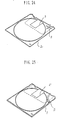
- FIG. 1 shows the front side of a cartridge C of one-side type in which informations are recorded on only one side of an optical disc or a magnetic disc
- FIG. 2 shows the back side of the cartridge C.
- the cartridge C has an upper shell half 1 and a lower shell half 2 in alignment with each other. At the center portion of the lower shell half 2 is formed a spindle hole 3 into which a spindle is inserted for rotating a disc d accommodated therein. A hub 20 provided at the center portion of the disc d is engaged with the spindle hole 3. A head insertion hole 4 is formed adjacent to the spindle hole 3 so that a write and read head is inserted into the spindle hole 3. The write and read head may be a read head which is not provided with a writing function.
- the upper shell half 1 has a magnetic bias hole 5 into which a magnetic head is inserted when informations are recorded again. In this cartridge, a spindle hole is not formed on the upper half shell 1.
- a shutter 7 is slidably provided at a guide portion G located at the end portion on the side of a recording and reproducing appatatus (player) in order to open and close the three holes.
- the shutter 7 is formed of a single metal sheet such as a stainless plate as shown in FIGS. 3 and 4.
- the shutter 7 has a long closing plate 8 whose lower end is guided by a retainer plate 6 (FIG.2).
- a short closing plate 12 is provided opposite to the long closing plate 8 whose lower end forms a guiding side l1 abutting against a guiding side l0 provided on the upper shell half 1 of the cartridge C (FIG.1).
- a slide portion 13 which has an elongated arm 13a extended from the bent portion.
- the slide portion 13 engages with the guide portion G formed at the end portion of the cartridge C on the side of a recording and reproducing apparatus when the cartridge C is inserted thereinto.
- the slide portion 13 has a guide groove engagement part 11 at its one end while the slide portion 13 has a spring engagement part 14 at the opposite side of the guide groove engagement part 11, to which one end of a spring 15 is fixed for urging the shutter 7 in one direction.
- the shutter 7 can be stably slid.
- the guide side l1 is guided by the guide side l0 formed on the upper shell half 1, the shutter 7 can be smoothly slid.
- the elongated arm 13a of the slide portion has a cutout 16 through which the write and read head H can be smoothly inserted into the head insertion hole 4 along the elongated direction of the cartridge C as shown in FIG.8.
- a cutout 22 At the front end of the cartridge C is formed a cutout 22 corresponding to the cutout 16 of the elongated arm 13a.
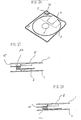
- FIGS. 5, 6 and 7 shows another shutter 107.
- the shutter 107 has a window frame 10 integrally formed on the short closing plate 12.
- the window frame 10 defines a window 9 which is opposed to the magnetic bias hole 5 when the shutter 107 is opened.
- the lower ends of the short closing plate 12 and the window frame 10 form a long guide side l10 which abuts against a guide side l0 formed on the upper shell half 1 of the cartridge C.
- FIG.9 show an embodiment of a cartridge of double-side type. This type of cartridge can be adapted for a double-side optical disc of 3.5 inches.
- the spindle hole 3 and the head insertion hole 4 are opened and closed by a shutter 30 (FIG.10) whose lower end is guided by a retainer plate 31.
- the shutter 30 is formed in such a manner that a sheet of stainless plate is bent at its enter portion.
- the shutter 30 has a pair of closing plates 32, 32 opposed to each other and a slide portion 33 at its bent portion.
- the slide portion 33 engages with the front side of the cartridge C1.
- Each closing plate 32 has a window 34 at a position opposed to each of the spindle hole 3 and the head insertion hole 4.
- the shutter 30 is urged by a spring (not shown) in the direction where the two holes 3, 4 are closed.
- the slide portion 33 has a recess 115 for receiving a drive pin P1 of the recording and reproducing apparatus.
- the shutter 30 is slidingly moved by the drive pin P1 and is returned to an original position to close the two holes 3, 4 when the drive pin P1 releases the shutter 30.
- the slide portion 33 has an elongated arm 36 at a position corresponding to the windows 34.
- the opposite ends of the elongated arm 36 in its lateral direction are provided with a pair of cutouts 37, 37 each of which correspond to the cutout 22 of the front end of the cartridge (FIG.9). These cutouts 22, 37 make it possible to guide smoothly the write and read head H into the head insertion hole 4.
- the elongated arm 37 has a guide groove engagement portion 39 at its distal end.
- FIG. 11 shows a modified embodiment of the shutter shown in FIGS. 3 and 4.
- a shutter 40 has an elongated arm 41 whose opposite sides are cut away to form a pair of cutouts 42, 42, respectively.
- the shutter 40 is moved by a drive pin (not shown) to open the head insertion hole 4.
- the write and read head H is inserted into the head insertion hole 4 in the direction indicated by an arrow A.
- the head H reads the informations on the disc d accommodated in the cartridge C2.
- the formation of the two cutouts 22, 42 make it possible to guide the head H close to the surface of the disc d.
- a magnetic head M is inserted into the magnetic bias hole 5 in the direction indicated by an arrow B at the same time when the write and read head H is inserted into the head insertion hole 4.
- the formation of the cutout 42 makes it possible to guide the head M close to the surface of the disc d thereby to increase ability for writing and reading the informations.
- the elongated arm 13a has a reinforcing piece 50 at its one side, which is formed in a manner that a cutout poirtion 13d is bent downwardly.
- the reinforcing piece 50 can effectively prevent the deformation of the elongated arm when the drive pin P pushes the guide groove engagement portion to move the shutter 55.
- the reinforcing piece 50 is bent perpendicular to the surface of the elongated arm to avoid obstruction of smooth insertion of the head H.
- FIG. 13 The shutter 55 in FIG. 13 is of the one-side type.
- FIG. 15 shows a shutter 56 of double-side type.
- the shutter 56 has a pair of long closing plates 8, 54 opposed to each other, and its elongated arm 13a has a pair of reinforcing pieces 51, 51 at its both ends, which are formed in a manner that a pair of cutouts 13e, 13e are bent perendicular to the surface of the elongated arm 13a (FIG. 16).
- the reinforcing pieces can guide the head H close to the surface of the disc d.
- An elongated arm 57 shown in FIGS. 17 and 18 has a configuration of an inverted mountain. In this case, the opposite end faces of the elongated arm 57 are extended in the direction of the insertion of the head H.
- the guide portion G of the cartridge C3 has, as shown in FIG. 19, a first guide surface 30 located at a downward position dropped from the upper end of the cartridge C3 and a second guide surface 31 at an upward position opposite to the first guide surface 30 with respect to the head insertion hole 4.
- the cutout 22 corresponding to the cutouts of elongated arms of the above shutters 7, 30, 40, 55, 56 107.
- a recess 15 for receiving the drive pin P is formed between the first surface 30 and the cutout 22. The drive pin P drops into the recess 15 when a shutter is moved to the right as viewed in FIG. 19 thereby to open completely the head insertion hole 4.
- first guide groove 120 and a second guide groove 121 located opposite to the first guide groove 120. These two grooves 120, 121 are extended through substantially total length of left and right parts of the cartridge C3.
- the first guide groove 120 is engaged with the guide groove engagement portion 11 of the shutter 7, 40, 55, 56 107, while the second guide groove 121 is engaged with a guide groove engagement portion 13b (FIGS. 4 and 7) located opposite to the portion 11.
- the first guide groove 120 is formed at a position lower than the bottom of the recess 115 while the second guide groove 121 is formed at a position upper than that of the first guide groove 120.
- the arrangement of the first and second guide grooves 120, 121 makes it possible to move the shutter steadily.
- the recess 115 has, as shown in FIG. 20, a first guide face 60 for guiding the drive pin P and a second guide face 61 opposite to the first guide face 60 and a bottom face 62.
- a curved surface 63 having a radius of r.
- the curved surface can guide smoothly the drive pin P into the recess 115 and, further, the amount of wear of the intersecting portion between the first guide surface 30 and the first guide face 60 becomes less to avoid the contamination of the disc surface due to dust caused by the movement of the shutter.
- the smooth movement of the drive pin P makes it possible to slide the shutter smoothly.
- a spring accommodating portion 70 At the end face of a spring accommodating portion 70 is provided a spring insertion inlet 71 through which the spring 15 is inserted thereinto.
- a wall defining the portion 70 has a reinforcing rib S which is formed not so as to obstruct the movement of the spring 15 as shown in FIGS. 21 to 28.
- the formation of the reinforcing rib S can prevent the deformation of the walls defining the spring accommodating portion 70 thereby to enable the shutter to move smoothly.
- Two reinforcing ribs S formed on the upper and lower shell halves, respectively, may be intersected when the upper and lower shell halves are assembled. That is, one rib S is provided with the upper shell 1 to form a triangle corner together with the two end sides of the upper shell half as shown in FIG. 22 while the other rib S is provided with the lower shell 2 along a diagonal line as shown in FIG. 23. Further, as shown in FIG. 24, the reinforcing rib S may be in the form of a cross.
- a reinforcing rib S may be in the form of an arc extending along the moving locus of a coil portion 15a of the coil spring 15 when the coil spring 15 is expanded and shrunken.
- the rib S may be formed on not only both shell halves 1, 2 but also either shell half 1 or 2.
- the rib S reinforces the wall of the cartridge and guides the coil portion 15a of the coil spring 15 thereby to enable the coil spring 15 to expand and shrink smoothly. This smooth movement of the spring 15 enalbles the shutter to move smoothly and steadily.
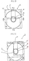
- FIGS. 29 and 30 shows two plan views of one-side cartridge as viewed from the front side and the back side, respectively.
- On the inner surfaces of the upper and lower shell halves 1, 2 are formed two annular ribs 81, 81, respectively, in which a disc is accommodated.
- the inner surface of the upper shell half 1 has an annular rib 83 at its center portion, the diameter of which is slightly larger than that of the hub 20 of the disc d.
- the rib 83 is opposed to a non-recording portion of the disc d, on which informations are not recorded (FIGS. 31 and 32).
- the height of the rib 83 projected from the inner surface 1b of the upper shell half 1 is determined at e. g., 0.3mm and the depth of the recess, surrounded by the rib 83, dropped from the lower surface of the rib 83 is determined at e. g., 0.6mm.
- the height of the hub 20 projected from the surface of the disc d is about 0.6mm. Accordingly, when the disc d is moved upwardly, the rib 83 abuts against the upper surface of the disc d to maintain a proper space between the disc d and the inner surface of the upper shell half 1. At this time, the hub 20 does not abut against the inner surface of the recess surrounded by the annular rib 83.
- the hub 20 is projected into the spindle hole 3 defined by an annular rib 82 thereby to refrain the movement of the disc d in its radial direction.
- a slanted corner 90 which is located at a position opposite to that of a slanted corner of a conventional magnetic disc cartridge.
- the cartridge C is normally adapted for a optical disc. Therefore, there is no fear that an operator inserts, by mistake, a conventional magnetic disc into a recording and reproducing apparatus for a optical disc.
- the cartridge C is accommodated in a case 93, as shown in FIG.33, which is made of polypropylene having a thickness of about 0.5mm.
- the case 93 has an inlet 93a which is provided with a pair of pick-up recesses 93b.
- the inner wall of the case 93 is rough (sand-like surface) to prevent the slip of the cartridge from the inside of the case 93 (FIG. 34).
- a side surface 93c and a bottom surface 93d are bonded by a supersonic sealing operation.
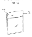
- the case 93 accommodating the disc cartridge C may be covered with a bag made of drawing polypropylene. Adhesive is applied to the covering piece 96a of the bag 96 to reliably close the inlet of the bag 96.
Landscapes
- Feeding And Guiding Record Carriers (AREA)
Abstract
Description
- The present invention relates to a disc cartridge for encasing a recording medium such as an optical disc or a magnetic disc.
- In general, a magnetic disc or an optical disc is encased in a cassette case made of two shell halves. A hole into which a spindle for rotating the disc is to be inserted is formed in a central portion of the cassette case. Adjacent to the spindle hole, a head insertion hole into which a write and read head is to be inserted is formed in the radial direction to traverse the recording surface of the disc. The head insertion hole is opened and closed by a shutter having an opening corresponding to the head insertion hole.
- However, in this disc cartridge, only the head insertion hole is closed by the shutter in a state wherein the spindle hole is exposed to the atmosphere. In this manner, if the spindle hole is exposed to the atmosphere, dust enters inside the cartridge to contaminate the surface of the disc.
- Moreover, since an opening of the shutter for opening and closing the spindle hole is simply formed so as to cut a rectangle portion of a planar plate of the cartridge, a write and read head cannot be inserted close to the surface of the disc when the head is inserted into the head insertion hole along the surface of the cartridge.
- In addition, the shutter is reciprocatingly moved, along a guide portion of the cartridge, by a drive pin provided in a recording and reproducing apparatus (player) and, however, the shutter cannot be smoothly moved because of various defects of the guide portion thereof.
- It is an object to provide a cartridge in which all openings of a cartridge can be closed and a shutter can be smoothly moved.
- It is another object to provide a cartridge in which a shutter is formed so that a write and read head is smoothly inserted in a longitudinal direction of a head insertion hole.
- According to this invention, there is provided a cartridge a disc cartridge for accommodating a disc therein, which comprises; a spindle hole into which a spindle is inserted to rotate the disc; a head insertion hole into which a read and/or write head is inserted and which is located adjacent to the spindle hole; and a shutter for closing and opening the spindle hole and a head insertion hole at the same time, which is slidingly moved along a guide portion formed at the front end of the cartridge, opposed to a recording and reproducing apparatus, which is urged by an elastic member in the direction where the spindle hole and the head insertion hole are closed, and which is formed in a manner that a sheet of plate is bent to provide a pair of closing plates opposite to each other, at least one of the two closing plates closing the spindle hole and the head insertion hole at the same time, a bent portion between the two closing plates forming a slide portion for engaging with the guide portion, the slide portion having an elongated arm extending in its longitudinal direction, one end of the elastic member being fixed to one end of the slide portion, a guide groove engagement portion for engaging with a guide groove provided on the guide portion being formed at a front end of the elongated arm.
- The nature, utility, and further features of this invention will be more clearly apparent from the following detailed description with respect to preferred embodiments of the invention when read in conjunction with the accompanying drawings briefly described below.
- In the accompanying drawings:
- FIG.1 is a perspective view of a cartridge, as viewed from the side of an upper shell half, showing a first embodiment of this invention;
- FIG. 2 is a perspective view, as viewed from the side of a lower shell half, showing the first embodiment of this invention;
- FIG. 3 is a perspective view of a shutter as viewed in a certain direction;
- FIG. 4 is a perspective view of the shutter in FIG. 3 as viewed in another direction;
- FIG. 5 is a perspective view of a cartridge showing a second embodiment of this invention;
- FIG. 6 is a perspective view of a shutter as viewed in a certain direction;
- FIG. 7 is a perspective view of the shutter in FIG.6 as viewed in another direction;
- FIG. 8 is a perspective view of a cartridge in which a shutter is opened;
- FIG. 9 is a perspective view of a cartridge of double-side disc type, showing a third embodiment of this invention;
- FIG. 10 is a perspective view of a shutter for a cartridge of double-side disc type;
- FIG. 11 is a perspective view of a shutter for a cartride of write and read type, showing a fourth embodiment of this invention;
- FIG. 12 is a perspective wiew of a cartridge provided with the shutter in FIG. 11;
- FIG. 13 is a perspective view of a cartridge of one-side type, showing a fifth embodiment of this invention;
- FIG. 14 is a cross-sectional view of an elongated arm of the cartridge of FIG. 13;
- FIG. 15 is a perspective view of a cartridge of double-side type, showing a sixth embodiment of this invention;
- FIG. 16 is a cross-sectional view of an elongated arm of the cartridge in FIG. 15;
- FIG. 17 is a partial perspective view of another elongated arm;
- FIG. 18 is a cross-sectional view of the elongated arm in FIG. 17;
- FIG. 19 is a plan view of a lower shell half of a cartride, showing a seventh embodiment of this invention;
- FIG. 20 is an enlarged view of a recess for receiving a drive pin;
- FIG. 21 is an enlarged view of a spring accommodating space of a cartridge, showing a ninth embodiment of this invention;
- FIG. 22 is a perspective view of an upper shell half of a cartridge having a reinforcing rib;
- FIG. 23 is a perspective view of a lower shell half of a cartridge having a reinforcing rib;
- FIG. 24 is a perspective view of a lower shell half of a cartridge having a reinforcing rib in another form:
- FIG. 25 is a perspective view of an upper shell half of a cartridge having a reinforcing rib in still another form;
- FIG. 26 is a perspective view of a lower shell half of a cartridge having a reinforcing rib in still another form;
- FIG. 27 is an elevational view of a spring accommodating space of a cartridge formed by the upper and lower shell halves in FIGS 25 and 26, respectively;
- FIG. 28 is an elevational view of a spring accommodating space of a cartridge whose upper shell half has a reinforcing rib;
- FIG. 29 is a plan view of a cartridge as viewed from the upper shell half thereof, showing a tenth embodiment;
- FIG. 30 is a plan view of a cartridge as viewed from the lower shell half thereof;
- FIG. 31 is a cross-sectional view taken along the line A-A of FIG. 29;
- FIG. 32 is a cross-sectional view talken along the line B-B of FIG. 29;
- FIG. 33 is a perspective view of a cartridge and a case, showing an eleventh embodiment of this invention;
- FIG. 34 is an elevational view of a case wall of a case in FIG. 33; and
- FIG. 35 is a perspective view of a bag accommodating therein the cartridge and the case in FIG. 33.
- FIG. 1 shows the front side of a cartridge C of one-side type in which informations are recorded on only one side of an optical disc or a magnetic disc, and FIG. 2 shows the back side of the cartridge C.
- The cartridge C has an
upper shell half 1 and alower shell half 2 in alignment with each other. At the center portion of thelower shell half 2 is formed aspindle hole 3 into which a spindle is inserted for rotating a disc d accommodated therein. Ahub 20 provided at the center portion of the disc d is engaged with thespindle hole 3. Ahead insertion hole 4 is formed adjacent to thespindle hole 3 so that a write and read head is inserted into thespindle hole 3. The write and read head may be a read head which is not provided with a writing function. Theupper shell half 1 has amagnetic bias hole 5 into which a magnetic head is inserted when informations are recorded again. In this cartridge, a spindle hole is not formed on theupper half shell 1. Ashutter 7 is slidably provided at a guide portion G located at the end portion on the side of a recording and reproducing appatatus (player) in order to open and close the three holes. Theshutter 7 is formed of a single metal sheet such as a stainless plate as shown in FIGS. 3 and 4. Theshutter 7 has along closing plate 8 whose lower end is guided by a retainer plate 6 (FIG.2). Ashort closing plate 12 is provided opposite to thelong closing plate 8 whose lower end forms a guiding side ℓ₁ abutting against a guiding side ℓ₀ provided on theupper shell half 1 of the cartridge C (FIG.1). - At the bent portion of the
shutter 7 is formed aslide portion 13 which has anelongated arm 13a extended from the bent portion. Theslide portion 13 engages with the guide portion G formed at the end portion of the cartridge C on the side of a recording and reproducing apparatus when the cartridge C is inserted thereinto. Theslide portion 13 has a guidegroove engagement part 11 at its one end while theslide portion 13 has aspring engagement part 14 at the opposite side of the guidegroove engagement part 11, to which one end of aspring 15 is fixed for urging theshutter 7 in one direction. - In this manner, if the
slide portion 13 is formed long and if theshutter 7 is slidingly moved while the guidegroove engagement part 11 located at its distal end is engaged with a guide groove go of the guide portion G, theshutter 7 can be stably slid. In addition, as the guide side ℓ₁ is guided by the guide side ℓ₀ formed on theupper shell half 1, theshutter 7 can be smoothly slid. - The
elongated arm 13a of the slide portion has acutout 16 through which the write and read head H can be smoothly inserted into thehead insertion hole 4 along the elongated direction of the cartridge C as shown in FIG.8. At the front end of the cartridge C is formed acutout 22 corresponding to thecutout 16 of theelongated arm 13a. - These structures of the cartridge C make it possible to simultaneously close the spindle hole and the head insertion hole and to stably move the shutter. Further, the write and read head can be smoothly inserted into the
head insertion hole 4 in its longitudinal direction. - FIGS. 5, 6 and 7 shows another
shutter 107. Theshutter 107 has awindow frame 10 integrally formed on theshort closing plate 12. Thewindow frame 10 defines awindow 9 which is opposed to themagnetic bias hole 5 when theshutter 107 is opened. The lower ends of theshort closing plate 12 and thewindow frame 10 form a long guide side ℓ₁₀ which abuts against a guide side ℓ₀ formed on theupper shell half 1 of the cartridge C. FIG.9 show an embodiment of a cartridge of double-side type. This type of cartridge can be adapted for a double-side optical disc of 3.5 inches. Thespindle hole 3 and thehead insertion hole 4 are opened and closed by a shutter 30 (FIG.10) whose lower end is guided by aretainer plate 31. - The
shutter 30 is formed in such a manner that a sheet of stainless plate is bent at its enter portion. Theshutter 30 has a pair ofclosing plates slide portion 33 at its bent portion. Theslide portion 33 engages with the front side of the cartridge C₁. Each closingplate 32 has awindow 34 at a position opposed to each of thespindle hole 3 and thehead insertion hole 4. When the twowindows 34 are opposed to the twoholes holes shutter 30 is urged by a spring (not shown) in the direction where the twoholes slide portion 33 has arecess 115 for receiving a drive pin P₁ of the recording and reproducing apparatus. Theshutter 30 is slidingly moved by the drive pin P₁ and is returned to an original position to close the twoholes shutter 30. - At one end of the
slide portion 33 is formed a slantingsurface 35 for guiding smoothly a so-called useless pin, i.e., unnecessary opening and closing pin P₀. Theslide portion 33 has anelongated arm 36 at a position corresponding to thewindows 34. The opposite ends of theelongated arm 36 in its lateral direction are provided with a pair ofcutouts cutout 22 of the front end of the cartridge (FIG.9). Thesecutouts head insertion hole 4. Theelongated arm 37 has a guidegroove engagement portion 39 at its distal end. - FIG. 11 shows a modified embodiment of the shutter shown in FIGS. 3 and 4. A
shutter 40 has an elongated arm 41 whose opposite sides are cut away to form a pair ofcutouts - The function of the
shutter 40 will now be explained with respect to FIG. 12. - First, when the informations on the disc d are read, the
shutter 40 is moved by a drive pin (not shown) to open thehead insertion hole 4. Then, the write and read head H is inserted into thehead insertion hole 4 in the direction indicated by an arrow A. The head H reads the informations on the disc d accommodated in the cartridge C₂. At this time, the formation of the twocutouts magnetic bias hole 5 in the direction indicated by an arrow B at the same time when the write and read head H is inserted into thehead insertion hole 4. Also, at this time, the formation of thecutout 42 makes it possible to guide the head M close to the surface of the disc d thereby to increase ability for writing and reading the informations. - In case that the above elongated arms have the cutouts, the strength of the arms become low. Therefore, it is desirable to reinforce the weak elongated arms as shown in FIGS. 13 to 18. In FIGS. 13 and 14, the
elongated arm 13a has a reinforcingpiece 50 at its one side, which is formed in a manner that acutout poirtion 13d is bent downwardly. The reinforcingpiece 50 can effectively prevent the deformation of the elongated arm when the drive pin P pushes the guide groove engagement portion to move the shutter 55. Moreover, the reinforcingpiece 50 is bent perpendicular to the surface of the elongated arm to avoid obstruction of smooth insertion of the head H. - The shutter 55 in FIG. 13 is of the one-side type. In contrast, FIG. 15 shows a shutter 56 of double-side type. The shutter 56 has a pair of
long closing plates elongated arm 13a has a pair of reinforcing pieces 51, 51 at its both ends, which are formed in a manner that a pair of cutouts 13e, 13e are bent perendicular to the surface of theelongated arm 13a (FIG. 16). The reinforcing pieces can guide the head H close to the surface of the disc d. - An
elongated arm 57 shown in FIGS. 17 and 18 has a configuration of an inverted mountain. In this case, the opposite end faces of theelongated arm 57 are extended in the direction of the insertion of the head H. - The guide portion G of the cartridge C₃ has, as shown in FIG. 19, a
first guide surface 30 located at a downward position dropped from the upper end of the cartridge C₃ and asecond guide surface 31 at an upward position opposite to thefirst guide surface 30 with respect to thehead insertion hole 4. - Between the first and
second surfaces cutout 22 corresponding to the cutouts of elongated arms of theabove shutters recess 15 for receiving the drive pin P is formed between thefirst surface 30 and thecutout 22. The drive pin P drops into therecess 15 when a shutter is moved to the right as viewed in FIG. 19 thereby to open completely thehead insertion hole 4. - Near the guide portion G of the
lower shell half 2 are formed afirst guide groove 120 and asecond guide groove 121 located opposite to thefirst guide groove 120. These twogrooves first guide groove 120 is engaged with the guidegroove engagement portion 11 of theshutter second guide groove 121 is engaged with a guidegroove engagement portion 13b (FIGS. 4 and 7) located opposite to theportion 11. Thefirst guide groove 120 is formed at a position lower than the bottom of therecess 115 while thesecond guide groove 121 is formed at a position upper than that of thefirst guide groove 120. The arrangement of the first andsecond guide grooves - The
recess 115 has, as shown in FIG. 20, a first guide face 60 for guiding the drive pin P and asecond guide face 61 opposite to the first guide face 60 and a bottom face 62. At an intersecting position of thefirst guide surface 30 and the first guide face 60 is formed a curved surface 63 having a radius of r. The curved surface can guide smoothly the drive pin P into therecess 115 and, further, the amount of wear of the intersecting portion between thefirst guide surface 30 and the first guide face 60 becomes less to avoid the contamination of the disc surface due to dust caused by the movement of the shutter. In addition, the smooth movement of the drive pin P makes it possible to slide the shutter smoothly. - At the end face of a spring accommodating portion 70 is provided a
spring insertion inlet 71 through which thespring 15 is inserted thereinto. A wall defining the portion 70 has a reinforcing rib S which is formed not so as to obstruct the movement of thespring 15 as shown in FIGS. 21 to 28. The formation of the reinforcing rib S can prevent the deformation of the walls defining the spring accommodating portion 70 thereby to enable the shutter to move smoothly. Two reinforcing ribs S formed on the upper and lower shell halves, respectively, may be intersected when the upper and lower shell halves are assembled. That is, one rib S is provided with theupper shell 1 to form a triangle corner together with the two end sides of the upper shell half as shown in FIG. 22 while the other rib S is provided with thelower shell 2 along a diagonal line as shown in FIG. 23. Further, as shown in FIG. 24, the reinforcing rib S may be in the form of a cross. - As shown in FIGS. 25 to 28, a reinforcing rib S may be in the form of an arc extending along the moving locus of a coil portion 15a of the
coil spring 15 when thecoil spring 15 is expanded and shrunken. The rib S may be formed on not only bothshell halves shell half coil spring 15 thereby to enable thecoil spring 15 to expand and shrink smoothly. This smooth movement of thespring 15 enalbles the shutter to move smoothly and steadily. - FIGS. 29 and 30 shows two plan views of one-side cartridge as viewed from the front side and the back side, respectively. On the inner surfaces of the upper and
lower shell halves upper shell half 1 has anannular rib 83 at its center portion, the diameter of which is slightly larger than that of thehub 20 of the disc d. Therib 83 is opposed to a non-recording portion of the disc d, on which informations are not recorded (FIGS. 31 and 32). - The height of the
rib 83 projected from the inner surface 1b of theupper shell half 1 is determined at e. g., 0.3mm and the depth of the recess, surrounded by therib 83, dropped from the lower surface of therib 83 is determined at e. g., 0.6mm. In a normal disc, the height of thehub 20 projected from the surface of the disc d is about 0.6mm. Accordingly, when the disc d is moved upwardly, therib 83 abuts against the upper surface of the disc d to maintain a proper space between the disc d and the inner surface of theupper shell half 1. At this time, thehub 20 does not abut against the inner surface of the recess surrounded by theannular rib 83. Thehub 20 is projected into thespindle hole 3 defined by anannular rib 82 thereby to refrain the movement of the disc d in its radial direction. - In FIG. 30, at the left front corner of the cartridge C is formed a
slanted corner 90 which is located at a position opposite to that of a slanted corner of a conventional magnetic disc cartridge. The cartridge C is normally adapted for a optical disc. Therefore, there is no fear that an operator inserts, by mistake, a conventional magnetic disc into a recording and reproducing apparatus for a optical disc. - The cartridge C is accommodated in a
case 93, as shown in FIG.33, which is made of polypropylene having a thickness of about 0.5mm. Thecase 93 has an inlet 93a which is provided with a pair of pick-uprecesses 93b. When a user takes the cartridge out of thecase 93, he holds the cartridge with his fingers through the pick-uprecesses 93b. The inner wall of thecase 93 is rough (sand-like surface) to prevent the slip of the cartridge from the inside of the case 93 (FIG. 34). Aside surface 93c and a bottom surface 93d are bonded by a supersonic sealing operation. - The
case 93 accommodating the disc cartridge C may be covered with a bag made of drawing polypropylene. Adhesive is applied to the covering piece 96a of thebag 96 to reliably close the inlet of thebag 96.
Claims (15)
Priority Applications (2)
| Application Number | Priority Date | Filing Date | Title |
|---|---|---|---|
| EP95101629A EP0653755B1 (en) | 1988-06-29 | 1989-06-28 | Disc cartridge |
| EP95101630A EP0653756B1 (en) | 1988-06-29 | 1989-06-28 | Disc cartridge |
Applications Claiming Priority (10)
| Application Number | Priority Date | Filing Date | Title |
|---|---|---|---|
| JP85106/88U | 1988-06-29 | ||
| JP1988085107U JPH0739104Y2 (en) | 1988-06-29 | 1988-06-29 | Single-sided disk cartridge shutter |
| JP85109/88U | 1988-06-29 | ||
| JP85107/88U | 1988-06-29 | ||
| JP85108/88U | 1988-06-29 | ||
| JP1988085103U JPH0739103Y2 (en) | 1988-06-29 | 1988-06-29 | Shutter guide structure for optical disk cartridge |
| JP1988085108U JPH0739105Y2 (en) | 1988-06-29 | 1988-06-29 | Single-sided disk cartridge shutter |
| JP85103/88U | 1988-06-29 | ||
| JP8510688U JPH0621097Y2 (en) | 1988-06-29 | 1988-06-29 | Single-sided disk cartridge shutter |
| JP1988085109U JPH0739106Y2 (en) | 1988-06-29 | 1988-06-29 | Double-sided optical disk cartridge shutter |
Related Child Applications (4)
| Application Number | Title | Priority Date | Filing Date |
|---|---|---|---|
| EP95101630A Division EP0653756B1 (en) | 1988-06-29 | 1989-06-28 | Disc cartridge |
| EP95101629A Division EP0653755B1 (en) | 1988-06-29 | 1989-06-28 | Disc cartridge |
| EP95101630.2 Division-Into | 1989-06-28 | ||
| EP95101629.4 Division-Into | 1989-06-28 |
Publications (3)
| Publication Number | Publication Date |
|---|---|
| EP0348937A2 true EP0348937A2 (en) | 1990-01-03 |
| EP0348937A3 EP0348937A3 (en) | 1990-06-27 |
| EP0348937B1 EP0348937B1 (en) | 1996-03-13 |
Family
ID=27525128
Family Applications (3)
| Application Number | Title | Priority Date | Filing Date |
|---|---|---|---|
| EP89111763A Expired - Lifetime EP0348937B1 (en) | 1988-06-29 | 1989-06-28 | Disc cartridge |
| EP95101629A Expired - Lifetime EP0653755B1 (en) | 1988-06-29 | 1989-06-28 | Disc cartridge |
| EP95101630A Expired - Lifetime EP0653756B1 (en) | 1988-06-29 | 1989-06-28 | Disc cartridge |
Family Applications After (2)
| Application Number | Title | Priority Date | Filing Date |
|---|---|---|---|
| EP95101629A Expired - Lifetime EP0653755B1 (en) | 1988-06-29 | 1989-06-28 | Disc cartridge |
| EP95101630A Expired - Lifetime EP0653756B1 (en) | 1988-06-29 | 1989-06-28 | Disc cartridge |
Country Status (3)
| Country | Link |
|---|---|
| US (1) | US5051857A (en) |
| EP (3) | EP0348937B1 (en) |
| DE (3) | DE68925929T2 (en) |
Cited By (6)
| Publication number | Priority date | Publication date | Assignee | Title |
|---|---|---|---|---|
| EP0494794A3 (en) * | 1991-01-11 | 1992-07-22 | Sony Corporation | Disc cartridge |
| EP0510681A3 (en) * | 1991-04-25 | 1993-10-06 | Sony Corporation | Disk cartridge |
| US5416654A (en) * | 1992-07-14 | 1995-05-16 | U.S. Philips Corporation | Method and device for snap opening of a cover of a cassette |
| EP0691650A3 (en) * | 1990-02-14 | 1997-07-23 | Dainippon Printing Co Ltd | Disk cartridge |
| EP0778569A3 (en) * | 1990-01-29 | 1997-09-24 | Dainippon Printing Co Ltd | Disk cartridge |
| WO1999008277A1 (en) * | 1997-08-08 | 1999-02-18 | Sony Corporation | Disc cartridge |
Families Citing this family (17)
| Publication number | Priority date | Publication date | Assignee | Title |
|---|---|---|---|---|
| JPH03113772A (en) * | 1989-09-22 | 1991-05-15 | Victor Co Of Japan Ltd | Small-sized magneto-optical disk device |
| JP2827332B2 (en) * | 1989-10-06 | 1998-11-25 | ソニー株式会社 | Disk cartridge |
| CA2062100C (en) * | 1991-03-05 | 2000-10-31 | Hirotoshi Fujisawa | Disc cartridge |
| US5815344A (en) * | 1992-02-17 | 1998-09-29 | Sony Corporation | Disc cartridge loading apparatus |
| US6721266B1 (en) * | 1992-07-23 | 2004-04-13 | Sony Corporation | Disc cartridge with slidably mounted shutter |
| US5515358A (en) * | 1993-01-14 | 1996-05-07 | Matsushita Electric Industrial Co., Ltd. | Disk cartridge and method for constructing the same |
| JPH0887851A (en) * | 1994-09-16 | 1996-04-02 | Sony Corp | Disc cartridge |
| USD366476S (en) | 1995-03-09 | 1996-01-23 | Nomai Sa | Disk cartridge |
| USD381644S (en) * | 1995-09-13 | 1997-07-29 | Imation Corp. | Triangle-shaped movable shutter for a data storage diskette cartridge |
| US5812351A (en) * | 1995-09-15 | 1998-09-22 | Imation Corp. | Raised-region having sloped edges under cleaning fabric in flexible magnetic recording diskette cartridge cover shell |
| US5980791A (en) * | 1996-07-17 | 1999-11-09 | Imation Corp. | Method for forming a molded-in lifter for cleaning a flexible magnetic disc |
| USD420999S (en) * | 1997-08-11 | 2000-02-22 | Sony Corporation | Shutter for magnetic disc cartridge |
| AU134900S (en) * | 1997-10-13 | 1998-08-31 | Sony Corp | Shutter for magnetic disc cartridge |
| US5969916A (en) * | 1997-11-12 | 1999-10-19 | Iomega Corporation | Disk cartridge with shutter opening arm alignment surface and retraction slot |
| JP4103257B2 (en) * | 1998-07-13 | 2008-06-18 | ソニー株式会社 | Disc cartridge |
| JP2000048522A (en) | 1998-07-24 | 2000-02-18 | Sony Corp | Disk cartridge |
| CA108613S (en) * | 2004-05-10 | 2006-10-26 | Sony Computer Entertainment Inc | Disk cartridge |
Family Cites Families (22)
| Publication number | Priority date | Publication date | Assignee | Title |
|---|---|---|---|---|
| JPS6138145Y2 (en) * | 1980-08-14 | 1986-11-04 | ||
| JPS5897166A (en) * | 1981-12-03 | 1983-06-09 | Sony Corp | Floppy disc cassette |
| JPS59177073U (en) * | 1983-05-13 | 1984-11-27 | ソニー株式会社 | disc cassette |
| US4626949A (en) * | 1983-05-19 | 1986-12-02 | Verbatim Corporation | Magnetic record disk cleaning and stabilizing assembly |
| JPS60145582A (en) * | 1984-01-09 | 1985-08-01 | Fujitsu Ltd | Magnetic disk cartridge |
| JPS60146953U (en) * | 1984-03-06 | 1985-09-30 | アルプス電気株式会社 | Recording/playback device for disk cartridges |
| NL8402602A (en) * | 1984-08-27 | 1986-03-17 | Philips Nv | DISC CASSETTE. |
| JPH0240626Y2 (en) * | 1984-10-26 | 1990-10-30 | ||
| JPH0351823Y2 (en) * | 1984-12-05 | 1991-11-07 | ||
| JPH0424536Y2 (en) * | 1985-04-15 | 1992-06-10 | ||
| JPS6290448U (en) * | 1985-11-22 | 1987-06-10 | ||
| US4794480A (en) * | 1986-04-21 | 1988-12-27 | Iomega Corporation | Bernoulli plate in cartridge |
| JPS6361484A (en) * | 1986-09-01 | 1988-03-17 | Toshiba Corp | Cartridge for information memory medium |
| JPS6370976A (en) | 1986-09-13 | 1988-03-31 | Hitachi Maxell Ltd | Disk cartridge |
| JPS6396784A (en) | 1986-10-13 | 1988-04-27 | Hitachi Maxell Ltd | Disk cartridge |
| JPS63306576A (en) * | 1987-06-08 | 1988-12-14 | Hitachi Maxell Ltd | Disk cartridge |
| US4858050A (en) * | 1987-06-09 | 1989-08-15 | Verbatim Corp. | Structurally rigid disk cartridge adaptable to eliminating relative axial cartridge and/or transducer head loading/unloading movement |
| CA1312375C (en) * | 1987-07-16 | 1993-01-05 | Sadao Kadokura | Magnetic recording disk cartridge |
| GB2208330B (en) * | 1987-07-27 | 1991-12-04 | Hitachi Ltd | An optical disc cartridge and a mechanism for preventing an incorrect insertion of a cartridge. |
| KR0124147B1 (en) * | 1987-07-29 | 1997-11-28 | 나가이 아쯔시 | Disc cartridge |
| JPH0739100Y2 (en) * | 1988-04-04 | 1995-09-06 | 日立マクセル株式会社 | Disk Cartridge |
| EP0650165B1 (en) * | 1988-04-28 | 1999-07-21 | Dai Nippon Insatsu Kabushiki Kaisha | Disc cartridge |
-
1989
- 1989-06-28 EP EP89111763A patent/EP0348937B1/en not_active Expired - Lifetime
- 1989-06-28 DE DE68925929T patent/DE68925929T2/en not_active Expired - Fee Related
- 1989-06-28 EP EP95101629A patent/EP0653755B1/en not_active Expired - Lifetime
- 1989-06-28 US US07/373,020 patent/US5051857A/en not_active Expired - Lifetime
- 1989-06-28 DE DE68929173T patent/DE68929173T2/en not_active Expired - Fee Related
- 1989-06-28 EP EP95101630A patent/EP0653756B1/en not_active Expired - Lifetime
- 1989-06-28 DE DE68929327T patent/DE68929327T2/en not_active Expired - Fee Related
Cited By (12)
| Publication number | Priority date | Publication date | Assignee | Title |
|---|---|---|---|---|
| EP0778569A3 (en) * | 1990-01-29 | 1997-09-24 | Dainippon Printing Co Ltd | Disk cartridge |
| EP0785554A3 (en) * | 1990-01-29 | 1998-03-18 | Dai Nippon Insatsu Kabushiki Kaisha | Method of manufacturing disk cartridge, disk cartridge produced by the same and mold for manufacturing disk cartridge |
| EP0691650A3 (en) * | 1990-02-14 | 1997-07-23 | Dainippon Printing Co Ltd | Disk cartridge |
| EP0690443A3 (en) * | 1990-02-14 | 1997-07-23 | Dainippon Printing Co Ltd | Disk cartridge |
| EP0690444A3 (en) * | 1990-02-14 | 1997-07-23 | Dainippon Printing Co Ltd | Disk cartridge |
| EP0494794A3 (en) * | 1991-01-11 | 1992-07-22 | Sony Corporation | Disc cartridge |
| US5467239A (en) * | 1991-01-11 | 1995-11-14 | Sony Corporation | Disc cartridge withribbed shutter |
| EP0510681A3 (en) * | 1991-04-25 | 1993-10-06 | Sony Corporation | Disk cartridge |
| US5315470A (en) * | 1991-04-25 | 1994-05-24 | Sony Corporation | Disk cartridge with centered magnetic plate |
| US5416654A (en) * | 1992-07-14 | 1995-05-16 | U.S. Philips Corporation | Method and device for snap opening of a cover of a cassette |
| WO1999008277A1 (en) * | 1997-08-08 | 1999-02-18 | Sony Corporation | Disc cartridge |
| US6327117B1 (en) | 1997-08-08 | 2001-12-04 | Sony Corporation | Recording/reproducing apertures for disc cartridge |
Also Published As
| Publication number | Publication date |
|---|---|
| DE68929173D1 (en) | 2000-04-13 |
| EP0653755A2 (en) | 1995-05-17 |
| EP0348937A3 (en) | 1990-06-27 |
| EP0348937B1 (en) | 1996-03-13 |
| DE68929173T2 (en) | 2000-07-13 |
| EP0653755A3 (en) | 1995-10-18 |
| DE68925929T2 (en) | 1996-07-18 |
| DE68929327D1 (en) | 2001-10-31 |
| EP0653756A2 (en) | 1995-05-17 |
| US5051857A (en) | 1991-09-24 |
| EP0653755B1 (en) | 2000-03-08 |
| EP0653756B1 (en) | 2001-09-26 |
| EP0653756A3 (en) | 1995-10-04 |
| DE68925929D1 (en) | 1996-04-18 |
| DE68929327T2 (en) | 2002-04-25 |
Similar Documents
| Publication | Publication Date | Title |
|---|---|---|
| EP0348937A2 (en) | Disc cartridge | |
| US5040167A (en) | Disk cartridge | |
| EP0778571B1 (en) | Disk cartridge | |
| EP0652563B1 (en) | Disc Cartridge | |
| EP0442502B1 (en) | Disk cartridge | |
| EP0421775B1 (en) | Disc cartridge | |
| JPS6361484A (en) | Cartridge for information memory medium | |
| EP0929070B1 (en) | Disk cartridge | |
| EP0793231B1 (en) | Tape cartridge | |
| US6866216B2 (en) | Cartridge | |
| JP2926015B2 (en) | cartridge | |
| JP3000753B2 (en) | Disk cartridge erroneous recording prevention mechanism | |
| JPS61211888A (en) | Disk cartridge | |
| JP2515313Y2 (en) | Disk cartridge | |
| JPH05342795A (en) | Disk cartridge | |
| KR100268589B1 (en) | Disc cartridge | |
| JP2925852B2 (en) | Method of manufacturing cartridge and shutter in cartridge | |
| JP2654423B2 (en) | Disk cartridge | |
| JPH0739102Y2 (en) | 3.5 inch optical disk cartridge | |
| JPH1131371A (en) | Magnetic disk cartridge | |
| JPS6361486A (en) | Cartridge for information memory medium | |
| JP2000163907A (en) | Disk cartridge | |
| JP2000036176A (en) | Magnetic disk cartridge | |
| JPH09134582A (en) | Disk cartridge | |
| JPH033181A (en) | Disk cartridge |
Legal Events
| Date | Code | Title | Description |
|---|---|---|---|
| PUAI | Public reference made under article 153(3) epc to a published international application that has entered the european phase |
Free format text: ORIGINAL CODE: 0009012 |
|
| AK | Designated contracting states |
Kind code of ref document: A2 Designated state(s): DE FR GB NL |
|
| PUAL | Search report despatched |
Free format text: ORIGINAL CODE: 0009013 |
|
| AK | Designated contracting states |
Kind code of ref document: A3 Designated state(s): DE FR GB NL |
|
| 17P | Request for examination filed |
Effective date: 19900706 |
|
| 17Q | First examination report despatched |
Effective date: 19920609 |
|
| GRAA | (expected) grant |
Free format text: ORIGINAL CODE: 0009210 |
|
| AK | Designated contracting states |
Kind code of ref document: B1 Designated state(s): DE FR GB NL |
|
| XX | Miscellaneous (additional remarks) |
Free format text: TEILANMELDUNG 95101629.4 EINGEREICHT AM 28/06/89. |
|
| REF | Corresponds to: |
Ref document number: 68925929 Country of ref document: DE Date of ref document: 19960418 |
|
| ET | Fr: translation filed | ||
| GRAH | Despatch of communication of intention to grant a patent |
Free format text: ORIGINAL CODE: EPIDOS IGRA |
|
| PLBE | No opposition filed within time limit |
Free format text: ORIGINAL CODE: 0009261 |
|
| 26N | No opposition filed | ||
| REG | Reference to a national code |
Ref country code: GB Ref legal event code: IF02 |
|
| PGFP | Annual fee paid to national office [announced via postgrant information from national office to epo] |
Ref country code: FR Payment date: 20020524 Year of fee payment: 14 |
|
| PG25 | Lapsed in a contracting state [announced via postgrant information from national office to epo] |
Ref country code: FR Free format text: LAPSE BECAUSE OF NON-PAYMENT OF DUE FEES Effective date: 20040227 |
|
| REG | Reference to a national code |
Ref country code: FR Ref legal event code: ST |
|
| PGFP | Annual fee paid to national office [announced via postgrant information from national office to epo] |
Ref country code: NL Payment date: 20040524 Year of fee payment: 16 |
|
| PGFP | Annual fee paid to national office [announced via postgrant information from national office to epo] |
Ref country code: GB Payment date: 20040526 Year of fee payment: 16 |
|
| PGFP | Annual fee paid to national office [announced via postgrant information from national office to epo] |
Ref country code: DE Payment date: 20040608 Year of fee payment: 16 |
|
| PG25 | Lapsed in a contracting state [announced via postgrant information from national office to epo] |
Ref country code: GB Free format text: LAPSE BECAUSE OF NON-PAYMENT OF DUE FEES Effective date: 20050628 |
|
| PG25 | Lapsed in a contracting state [announced via postgrant information from national office to epo] |
Ref country code: NL Free format text: LAPSE BECAUSE OF NON-PAYMENT OF DUE FEES Effective date: 20060101 |
|
| PG25 | Lapsed in a contracting state [announced via postgrant information from national office to epo] |
Ref country code: DE Free format text: LAPSE BECAUSE OF NON-PAYMENT OF DUE FEES Effective date: 20060103 |
|
| GBPC | Gb: european patent ceased through non-payment of renewal fee |
Effective date: 20050628 |
|
| NLV4 | Nl: lapsed or anulled due to non-payment of the annual fee |
Effective date: 20060101 |