EP0348596A2 - Pilgerschrittwalzwerk zum Warmwalzen von Rohren - Google Patents
Pilgerschrittwalzwerk zum Warmwalzen von Rohren Download PDFInfo
- Publication number
- EP0348596A2 EP0348596A2 EP89102566A EP89102566A EP0348596A2 EP 0348596 A2 EP0348596 A2 EP 0348596A2 EP 89102566 A EP89102566 A EP 89102566A EP 89102566 A EP89102566 A EP 89102566A EP 0348596 A2 EP0348596 A2 EP 0348596A2
- Authority
- EP
- European Patent Office
- Prior art keywords
- bush
- spindle
- rolling mill
- rolling
- mandrel
- Prior art date
- Legal status (The legal status is an assumption and is not a legal conclusion. Google has not performed a legal analysis and makes no representation as to the accuracy of the status listed.)
- Withdrawn
Links
Images


Classifications
-
- B—PERFORMING OPERATIONS; TRANSPORTING
- B21—MECHANICAL METAL-WORKING WITHOUT ESSENTIALLY REMOVING MATERIAL; PUNCHING METAL
- B21B—ROLLING OF METAL
- B21B21/00—Pilgrim-step tube-rolling, i.e. pilger mills
- B21B21/04—Pilgrim-step feeding mechanisms
-
- B—PERFORMING OPERATIONS; TRANSPORTING
- B21—MECHANICAL METAL-WORKING WITHOUT ESSENTIALLY REMOVING MATERIAL; PUNCHING METAL
- B21B—ROLLING OF METAL
- B21B25/00—Mandrels for metal tube rolling mills, e.g. mandrels of the types used in the methods covered by group B21B17/00; Accessories or auxiliary means therefor ; Construction of, or alloys for, mandrels or plugs
- B21B25/06—Interchanging mandrels, fixing plugs on mandrel rods or cooling during interchanging mandrels
-
- B—PERFORMING OPERATIONS; TRANSPORTING
- B21—MECHANICAL METAL-WORKING WITHOUT ESSENTIALLY REMOVING MATERIAL; PUNCHING METAL
- B21C—MANUFACTURE OF METAL SHEETS, WIRE, RODS, TUBES, PROFILES OR LIKE SEMI-MANUFACTURED PRODUCTS OTHERWISE THAN BY ROLLING; AUXILIARY OPERATIONS USED IN CONNECTION WITH METAL-WORKING WITHOUT ESSENTIALLY REMOVING MATERIAL
- B21C45/00—Separating mandrels from work or vice versa
Definitions
- This invention relates to a crawl-process rolling mill for hot rolling pipes of a type which comprises a spindle formed with a seat which extends along the rolling axis and is adapted to accommodate a mandrel.
- a so-called mandrel-breaker bush is generally used which fits slidably over the mandrel and abuts against one end of the rolled pipe. With the bush tightened down and by applying a sharp pull to the mandrel in the axial direction, the mandrel can be released from the pipe.
- the mandrel is removed from the spindle and sent to a cooling station, and a new mandrel is set up.
- the mandrel change involves of necessity the handling of the mandrel-breaker bushes, which is currently performed by means of specially provided devices. This, additionally to making the rolling mill still more complex, contributes toward longer downtime in a rolling course.
- a crawl-process rolling mill being characterized in that it comprises a mandrel-breaker bush of substantially cradle-like shape mounted to the spindle in alignment relationship with said seat and being open thereinto, said bush being movable in a guided fashion along the rolling axis between two ledges formed on the spindle.
- the rolling mill comprises a locking means mounted on the spindle for locking the bush angularly.
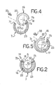
- the numeral 1 comprehensively designates a mitos rolling mill for hot rolling seamless pipes 2.
- the rolling mill 1 comprises a hydropneumatic box 3, known per se, which has a piston 4 movable in the direction of the rolling axis along guides 5 and rotatable about its own axis by a drive means, not shown, associated with the hydropneumatic box 3.
- the piston 4 has a piston rod 6 to which a spindle 7 is fitted to rotate as a unit therewith.
- the spindle 7 is formed with a cradle-shaped seat 8 which extends along the rolling axis and is accessible from the spindle outside axially through an axial opening provided at a forward end 7a of the spindle 7, as well radially through a longitudinal opening bordered laterally by two longitudinal edges 7b and 7c.
- the seat 8 receives a tang 9 of a mandrel 10 over which fits the pipe 2 being rolled.
- the rolling mill 1 comprises, in order to hold the mandrel 10 axially into the seat 8, retainer means 11 consisting of a groove 12 formed circumferentially around the tang 9 and having a cylindrical cross-section shape, for engagement by a raised portion 13 concentrical with the rolling axis and formed in the shape of a half-ring integrally with the cradle seat 8 and having the same length os the groove 12 in the axial direction.
- the sprung means 14 include an eave 14a adapted to overlap the tang 9 and hold it radially within the seat 8.
- pusher means 15 mounted on the hydropneumatic box 3 to act on the sprung means 14 to move the eave 14a from a position where it interferes with the cradle seat 8 to a position where it does not interfere with it, thereby the tang 9 is released and can be removed from the spindle 7.
- the rolling mill 1 comprises a so-called mandrel-breaker bush 16 mounted to the spindle 7 and effective to pull the mandrel 10 off the pipe 2 on completion of the rolling operation.
- the bush 16 is configured substantially cradle-like concentrically with the rolling axis and accessible from the outside both axially, and radially through a longitudinal opening bordered laterally by two parallel longitudinal edges 17 and 18 set at a distance apart, thereby the mandrel 10 can be inserted and withdrawn in the radial direction. Further, the bush 16 extends aligned to the cradle seat 8 in the spindle 7 and opens thereinto.
- the bush 16 can be driven in a guided fashion along the rolling axis between two edges 19 and 20 formed on the spindle 7, as explained in detail hereinafter.
- a rearward section 21 having, formed integrally on a free end thereof a radially raised collar 22 which fits slidably into a substantially half-ring-shaped groove 23 whose angular extension exceeds 180°, being formed in the cradle seat 8 between the raised portion 13 and the forward end 7a of the spindle 7.
- the groove 23 defines two walls, facing each other and lying perpendicularly to the rolling axis, which constitute said rearward 19 and forward 20 ledges for the collar 22. Furthermore, the axial length of the groove 23 represents, less the thickness of the collar 22, the stroke length of the bush 16 relatively to the spindle 7.
- the bush 16 also comprises, outside the spindle 7, a forward section 24 which also extends over a predetermined distance in the direction of the rolling axis and tapers toward it.
- the rolling mill 1 further comprises face interfit means 29 formed on one end of the forward section 24 of the bush 16 and adapted to engage one end of a pipe 2 being rolled.
- the interfit means 29 comprise a plurality of teeth 30 arranged annularly around the rolling axis and extending along it; furthermore, each tooth 30 has a back 30a tapering toward its free end.
- locking means collectively indicated at 31 are used and comprise a detent 32 affixed to the spindle 7, preferably in interfit relationship, at the edge 7b, and an insert 33 mounted removably by means of screws 34 on the opposed edge 7c. Both the detent 32 and the insert 33 jut out of their respective edges 7b and 7c of the spindle 7 over the cradle seat 8.
- Figure 4 depicts a start condition with the insert 33 removed from the edge 7c.
- the rearward section 21 of the bush 16 is inserted into the cradle seat 8 with a substantially pivotal movement (see Figure 5) by inserting the edge 17 of the bush 16 in between the edges 7b and 7c of the spindle 7, turning the bush 16, and sliding it into the seat 8 until the edge 17 abuts the detent 32.
- the insert 33 is then mounted on the edge 7c so as to retain the edge 18 and lock the bush 6 angularly (see Figure 2), with the collar 22 fitted in the groove 23.
- the pusher means 15 is first operated to move the eave 14a of the sprung means 14 to the position of no interference with the cradle seat 8, and the tang 9 of the mandrel 10 is then introduced radially into the seat 8 and the bush 16, with the groove 12 of the tang located at the raised portion 13.
- the mandrel 10 is retained axially by the fit of the raised portion 13 in the groove 12.
- the sprung means 14 are released to allow the eave 14a to locate at the interfering position so as to overlie the end of the tang 9 and hold the mandrel 10 radially.
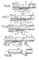
- the hot rolling of the pipe 2 on the pilgrim-process rolling mill 1 is carried out in a conventional manner not described herein. It matters to remark, however, that during the initial rolling steps, referred to as the tacking, the bush 10 locates at a partway retracted position inside the spindle 7, with the collar 22 abutting the rearward ledge 19 of the groove 23 and the face teeth 30 of the bush 16 in engagement with the rearward end of the pipe 2 and locking the pipe angularly to the bush.
- initial slip or play is advantageously prevented as may occur while the pipe 2 is yet to fit closely over the mandrel 10 and, accordingly, not yet unitized therewith, whereas as the rolling process progresses, the pipe 2 would tighten around the mandrel 10 by deformation.
- the mandrel 10 can be easile uncoupled angularly from the spindle 7, and the rotary motion required to roll the pipe 2 is imparted by the cited drive means of the hydropneumatic box 3 on the spindle 7, then on the bush 16 rigid rotatively with the spindle 7, and finally on the pipe 2 through the teeth 30.
- the mandrel-breaker rest 28 is first positioned in the groove 27 of the bush 16 (see Figure 6). Then, a first pull is applied in the axial direction, using conventional means and causing the spindle 7 and mandrel 10 to move back by a distance equal to the stroke length of the bush 16 as locked by the rest 28 relatively to the spindle 7, until the collar 22 abuts against the forward ledge 20 (see Figure 7), thereby the mandrel 10 is disengaged partway from the pipe 2.
- the mandrel-breaker bush is mounted directly to the spindle and does not require, therefore, to be manipulated and replaced on the occasion of a change of a mandrel at the end of a rolling course.
- tool handling, and specifically mandrel changes is made much easier, which reflects in improved reliability of the rolling mill.
- a further advantage afforded by a vocational-process rolling mill according to the invention is that by providing face interfit means between the mandrel-breaker bush and the pipe to be rolled, the rolling operations can be performed in an optimum manner even at the tacking stage, by eliminating any play or slip of the pipe.
- the pipe itself is made to cooperate mechanically with the bush, thereby the latter may have reduced size and weight to bring about lower costs.
Landscapes
- Engineering & Computer Science (AREA)
- Mechanical Engineering (AREA)
- Reduction Rolling/Reduction Stand/Operation Of Reduction Machine (AREA)
Applications Claiming Priority (2)
| Application Number | Priority Date | Filing Date | Title |
|---|---|---|---|
| IT2117788 | 1988-06-30 | ||
| IT21177/88A IT1217978B (it) | 1988-06-30 | 1988-06-30 | Laminatoio a passo di pellegrino per la laminazione a caldo di tubi |
Publications (2)
| Publication Number | Publication Date |
|---|---|
| EP0348596A2 true EP0348596A2 (de) | 1990-01-03 |
| EP0348596A3 EP0348596A3 (de) | 1991-10-02 |
Family
ID=11177935
Family Applications (1)
| Application Number | Title | Priority Date | Filing Date |
|---|---|---|---|
| EP19890102566 Withdrawn EP0348596A3 (de) | 1988-06-30 | 1989-02-15 | Pilgerschrittwalzwerk zum Warmwalzen von Rohren |
Country Status (2)
| Country | Link |
|---|---|
| EP (1) | EP0348596A3 (de) |
| IT (1) | IT1217978B (de) |
Cited By (1)
| Publication number | Priority date | Publication date | Assignee | Title |
|---|---|---|---|---|
| WO2007110416A1 (en) * | 2006-03-27 | 2007-10-04 | Danieli & C. Officine Meccaniche S.P.A. | Mandrel holder head with release device |
Family Cites Families (7)
| Publication number | Priority date | Publication date | Assignee | Title |
|---|---|---|---|---|
| HU155159A (de) * | 1964-10-21 | |||
| FR2060414A1 (en) * | 1969-09-05 | 1971-06-18 | Innocenti Gle Ind Metal | Mandrel arrangement for seamless tube - reciprocating rolling mill |
| SU450603A1 (ru) * | 1972-12-22 | 1974-11-25 | Предприятие П/Я В-8173 | Дорновое устройство подающего аппарата пилигримового стана |
| IT1011620B (it) * | 1974-03-22 | 1977-02-10 | Innocenti Santeustacchio Spa | Dispositivo di demandrinaggio per laminatoi a passo di pellegrino |
| SU740318A1 (ru) * | 1976-06-08 | 1980-06-15 | Предприятие П/Я В-8173 | Дорновое устройство подающего аппарата пилигримового стана |
| IT1217979B (it) * | 1988-06-30 | 1990-03-30 | Innocenti Santeustacchio Spa | Laminatoio a basso di pellegrino |
| IT1217980B (it) * | 1988-06-30 | 1990-03-30 | Innocenti Santeustacchio Spa | Laminatoio a passo di pellegrino |
-
1988
- 1988-06-30 IT IT21177/88A patent/IT1217978B/it active
-
1989
- 1989-02-15 EP EP19890102566 patent/EP0348596A3/de not_active Withdrawn
Cited By (4)
| Publication number | Priority date | Publication date | Assignee | Title |
|---|---|---|---|---|
| WO2007110416A1 (en) * | 2006-03-27 | 2007-10-04 | Danieli & C. Officine Meccaniche S.P.A. | Mandrel holder head with release device |
| CN101410197B (zh) * | 2006-03-27 | 2010-12-08 | 达涅利机械工业有限公司 | 带有释放装置的芯棒支座头 |
| RU2405641C2 (ru) * | 2006-03-27 | 2010-12-10 | Даньели Энд К. Оффичине Мекканике С.П.А. | Головка держателя оправки с устройством разгрузки |
| US9446438B2 (en) | 2006-03-27 | 2016-09-20 | Danieli & C. Officine Meccaniche S.P.A. | Mandrel holder head with release device |
Also Published As
| Publication number | Publication date |
|---|---|
| EP0348596A3 (de) | 1991-10-02 |
| IT1217978B (it) | 1990-03-30 |
| IT8821177A0 (it) | 1988-06-30 |
Similar Documents
| Publication | Publication Date | Title |
|---|---|---|
| EP0581385B1 (de) | Kaltexpansion für geschlitzte Buchse | |
| EP0605916B1 (de) | Verfahren zur Herstellung eines Kupplungsgehäuses | |
| US4302958A (en) | Making rings from tube stock | |
| EP0995584B1 (de) | Reifenwulstwickelvorrichtung und verfahren | |
| EP0275369B1 (de) | Maschine zum Formen von Konus und Flansch an Sprühdosen und dergleichen | |
| EP1259334B1 (de) | Vorrichtung zum auf- und abwickeln von dünnen bändern mit automatischer zentrierung | |
| EP0348596A2 (de) | Pilgerschrittwalzwerk zum Warmwalzen von Rohren | |
| JP2009208184A (ja) | 組付装置 | |
| US4355450A (en) | Method of operating a tube extracting mechanism | |
| JPH0354241B2 (de) | ||
| EP0348589A2 (de) | Pilgerwalzwerk | |
| US5315904A (en) | Apparatus for cutting inner circumferential surface of thick walled small diameter pipe | |
| US4395897A (en) | Rolling head support assembly for a rolling mill | |
| JPH07223005A (ja) | 圧延機ロールとチョックの固定装置および固定方法 | |
| US4488421A (en) | Mandrel-carrier head for a restrained-mandrel continuous rolling mill | |
| US4467631A (en) | Apparatus for splining thin-wall power transmission sleeves | |
| EP2007533B9 (de) | Dornhalterkopf mit trennvorrichtung | |
| EP0348588A2 (de) | Pilgerwalzwerk | |
| US4102244A (en) | Pot broach | |
| CN218835598U (zh) | 用于皮尔格冷轧机的送进小车 | |
| EP0040971A2 (de) | Verfahren und Vorrichtung zum Verbinden eines Rohres mit einem Flansch | |
| JP2799986B2 (ja) | ローラストレートナーおよびロール交換装置 | |
| JP4089993B2 (ja) | シール部材自動挿入装置及び挿入方法 | |
| CN211439137U (zh) | 一种多刀位刀库 | |
| JP4123549B2 (ja) | マンドレル緊急引抜装置およびそれを用いるマンドレルミル |
Legal Events
| Date | Code | Title | Description |
|---|---|---|---|
| PUAI | Public reference made under article 153(3) epc to a published international application that has entered the european phase |
Free format text: ORIGINAL CODE: 0009012 |
|
| AK | Designated contracting states |
Kind code of ref document: A2 Designated state(s): AT BE CH DE ES FR GB GR IT LI LU NL SE |
|
| PUAL | Search report despatched |
Free format text: ORIGINAL CODE: 0009013 |
|
| AK | Designated contracting states |
Kind code of ref document: A3 Designated state(s): AT BE CH DE ES FR GB GR IT LI LU NL SE |
|
| 17P | Request for examination filed |
Effective date: 19920314 |
|
| RAP1 | Party data changed (applicant data changed or rights of an application transferred) |
Owner name: INNSE INNOCENTI ENGINEERING S.P.A. |
|
| 17Q | First examination report despatched |
Effective date: 19930823 |
|
| STAA | Information on the status of an ep patent application or granted ep patent |
Free format text: STATUS: THE APPLICATION IS DEEMED TO BE WITHDRAWN |
|
| 18D | Application deemed to be withdrawn |
Effective date: 19940104 |