EP0348566A1 - Erkennungssystem für Ferngläser und Fernrohre - Google Patents
Erkennungssystem für Ferngläser und Fernrohre Download PDFInfo
- Publication number
- EP0348566A1 EP0348566A1 EP88305922A EP88305922A EP0348566A1 EP 0348566 A1 EP0348566 A1 EP 0348566A1 EP 88305922 A EP88305922 A EP 88305922A EP 88305922 A EP88305922 A EP 88305922A EP 0348566 A1 EP0348566 A1 EP 0348566A1
- Authority
- EP
- European Patent Office
- Prior art keywords
- objective lens
- principal
- lens
- binocular
- magnification
- Prior art date
- Legal status (The legal status is an assumption and is not a legal conclusion. Google has not performed a legal analysis and makes no representation as to the accuracy of the status listed.)
- Granted
Links
- 230000003287 optical effect Effects 0.000 claims abstract description 32
- 230000004438 eyesight Effects 0.000 claims abstract description 5
- 230000000903 blocking effect Effects 0.000 claims description 2
- 239000000835 fiber Substances 0.000 claims 1
- 238000010276 construction Methods 0.000 description 4
- 230000000994 depressogenic effect Effects 0.000 description 2
- 230000000694 effects Effects 0.000 description 2
- 230000002411 adverse Effects 0.000 description 1
- 230000001427 coherent effect Effects 0.000 description 1
- 238000004519 manufacturing process Methods 0.000 description 1
- 230000011514 reflex Effects 0.000 description 1
- 230000007474 system interaction Effects 0.000 description 1
Images
Classifications
-
- G—PHYSICS
- G02—OPTICS
- G02B—OPTICAL ELEMENTS, SYSTEMS OR APPARATUS
- G02B23/00—Telescopes, e.g. binoculars; Periscopes; Instruments for viewing the inside of hollow bodies; Viewfinders; Optical aiming or sighting devices
- G02B23/16—Housings; Caps; Mountings; Supports, e.g. with counterweight
- G02B23/18—Housings; Caps; Mountings; Supports, e.g. with counterweight for binocular arrangements
-
- G—PHYSICS
- G02—OPTICS
- G02B—OPTICAL ELEMENTS, SYSTEMS OR APPARATUS
- G02B23/00—Telescopes, e.g. binoculars; Periscopes; Instruments for viewing the inside of hollow bodies; Viewfinders; Optical aiming or sighting devices
- G02B23/02—Telescopes, e.g. binoculars; Periscopes; Instruments for viewing the inside of hollow bodies; Viewfinders; Optical aiming or sighting devices involving prisms or mirrors
-
- G—PHYSICS
- G02—OPTICS
- G02B—OPTICAL ELEMENTS, SYSTEMS OR APPARATUS
- G02B23/00—Telescopes, e.g. binoculars; Periscopes; Instruments for viewing the inside of hollow bodies; Viewfinders; Optical aiming or sighting devices
- G02B23/14—Viewfinders
Definitions
- This invention relates to telescopes and binoculars, and more particularly pertains to a novel spotting system for such instruments which facilitates locating the target and which permits instantaneous shift to magnification of the target after it is located.
- Binoculars are usually provided with magnifying capacities or power ranges of from 6x to 10x and at the latter magnifying power the field of view is fairly limited. Consequently, if one wants to locate a target, e.g., an airplane in the sky or a buoy at sea, it usually means sighting through the binocular and scanning the field of vision more or less randomly until the target is picked up. In some cases the approximate general location of the target can be ascertained with the naked eye; however, one is still faced with then having to locate the target through the binocular at the magnifying power. Since the field of view is limited, this can be a difficult task especially in those instances where the target is small or is moving.
- a zoom lens arrangement could be employed, the lower power being used first to sight the target and the magnifying power thereafter increased as desired.
- To achieve the desired magnification takes time as the relative positions of the optical elements in the zoom lens arrangement are changed to effect magnification. During this time the target may have moved out of the field of view, necessitating relocation of the target.
- zoom lenses because of their relatively sophisticated and complex construction are expensive to manufacture, cannot stand up to rough handling and are susceptible to failure in severe or adverse use conditions. Further, such lenses are bulky and increase the weight as well as the cost of the binocular.
- the invention seeks to provide a novel spotting system for binoculars and telescopes which facilitates target location and magnification of the target.
- a telescope or binocular comprises a barrel and, within the barrel, (a) a principal objective lens and an ocular lens defining a principal magnification optical path; (b) an auxiliary objective lens; (c) light diverting means comprising a mirror movable between a first and a second position; and (d) actuation means adapted to displace said mirror from said first position to said second position and from said second position to said first position; said movable mirror in said first position reflecting light passing through said auxiliary objective lens onto the focal plane of said ocular lens to permit a substantially unmagnified view through said ocular lens and blocking said principal magnification optical path, and in said second position breaking said optical path through said auxiliary objective lens and opening said principal magnification optical path to permit the magnified target image to be viewed through said ocular lens.
- the user first sights through the telescope or binocular with the movable mirror in its first position and the active light path through the spotting system which comprises the auxiliary objective lens, and is thus afforded a wide field of view with substantially no magnification.
- the user can then shift the mirror into its second position thereby breaking the light path through the spotting system and the active light path is through the principal magnification system.
- the principal magnification optical path has a fixed magnification of from 6x to 10x.
- the auxiliary lens desirably lies proximate to, and substantially coplanar with, the principal objective lens.
- a principal magnification optical path field of view indicator means is situated between said auxiliary objective lens and said ocular lens, said field of view indicator means defining the area to be viewed through said principal magnification optical path when said optical path through said objective lens and said field of view indicator means is broken.
- the user can thus move the binocular until the desired target is within the field indicator, and on changing the position of the movable mirror the area in the field indicator will then appear in the user's view magnified to the power of the principal magnification system.
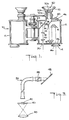
- a binocular incorporating the subject invention is identified generally by the reference numeral 10 in Fig. 1.
- the spotting system of the present invention is adapted for use in a conventional prism binocular.
- the subject invention is adapted for use in a conventional telescope and the terms binocular and telescope are used interchangeably herein.
- the prism binocular 10 includes two barrels 12 each of which house the principal magnification optics of the binocular principal magnifying optics system.
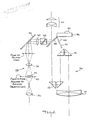
- the details of the construction of the spotting system and the system's interaction with the principal magnification system of the binoculars can be understood best with reference to Fig. 2, wherein the principal magnification optical system is identified generally by reference numeral 26 and includes the principal objective lens 14, prism sets 16 and 18, and ocular lens 20 which function in the manner described above.
- the auxiliary spotting system 28 includes an auxiliary objective lens 30 of the same focal length as the ocular lens 20 mounted at the front of the binocular preferably in the same plane as and proximate the principal objective Lens 14.
- the auxiliary objective lens 30 has a relatively small diameter as compared to the principal objective lens 14 and will be equal to or only slightly greater than the diameter of the ocular lens 20.
- the image created by the auxiliary objective lens 30 will appear between one and two focal lengths (depending upon the distance to the target) behind said lens. Since the ocular lens 20 is in a relatively fixed position with respect to the lens 30 a gap exists between the image plane of the lens 30 and the focal plane of the ocular lens 20.
- An image transfer arrangement is therefore utilized to bridge this optical gap, and may include one or more lenses of a suitable focal length so as to produce a 1x magnification of the spotting system, comprising lens 30, the transfer lenses and the ocular lens 20.
- the focal length of the auxiliary lens 30 is equal to the focal length of lens 20.
- the lenses 32 and 34 are arranged so that the optical system composed of lenses 30, 32, 34 and 20 produces a 1x magnification to an observer with normal eyesight. A slight deviation from these criteria caused by the fact that the image of the auxiliary objective lens 30 might be at differing locations depending on the distance to the viewed target will have the effect that said target viewed through the spotting system will be slightly magnified; however this will not detract from the present invention.
- a transfer lens arrangement is shown as comprising a first transfer lens 32 and a second transfer lens 34 with a mirror 36 positioned therebetween to reflect the light at a forty-five degree angle to assist in routing the light path of the spotting system to the ocular lens.
- the transfer lenses 32 and 34 will also invert the image and this can be rectified by a prism arrangement 38 which functions in a manner similar to the prism arrangement in the principal magnification system.
- the image transfer arrangement could consist of a fiberoptics image conduit 39 (coherent fiberoptics bundle) in lieu of the transfer lenses 32 and 34, and mirror 36 as shown in Fig. 3.
- a transparent plate 40 is positioned on the focal plane of the auxiliary objective lens 30.
- the plate 40 bears indicia 42 to indicate to one sighting through the spotting system the field of view at that instant of the principal magnifying system.
- the indicia may be simply a circle inscribed on the plate, a color tinted disk or other conventional means.
- a means is provided to allow the user to switch from the spotting system to the principal magnification system almost instantaneously.
- the principal magnification system and the spotting system are configured so that a movable mirror 44 can be positioned in the light path of the principal magnification system between the prisms 18 and the ocular lens 20 and in the light path of the spotting system between the prisms 38 and the ocular lens 20.
- An actuation mechanism 46 similar to one used in singlelens reflex cameras is adapted to move the mirror 44 between first and second positions. With mirror 44 in its first position (48 in Fig. 2) it obstructs or blocks the light path through the principal magnifying system.
- the operating or active light path is through the spotting system, i.e., through the auxiliary objective lens 30, plate 40, transfer lens 32, mirror 36, transfer lens 34, prisms 38, and off mirror 44 to the ocular lens 20.
- the field of view will include the principal field of view indicator to facilitate the location of the target.
- the mirror 44 moves into its second position (52 in Fig. 2) will break the optical path through the spotting system, and open the principal magnification optical path so it becomes the operating or active light path.
- the area seen in the field of view indicator in the spotting system will now appear in view magnified to the power of the principal magnification system.
- the actuation mechanism may be of conventional construction well known to those skilled in the art. It may be such button actuated as shown in which case the movable mirror 44 is normally in its first position and will move to its second position when the actuation button is pressed and remain there as long as the button remains depressed. Alternatively, the movable mirror may normally rest in its second position, moving into the first position when the actuation button is depressed.
- spotting system discussed above need be provided in only one barrel of the binocular to the effective.
- spotting systems can be provided in both barrels.
- Some advantages of the present invention evident from the foregoing description include a spotting system for binoculars which facilitates target location and which will permit instantaneous magnification of the target once located.
Landscapes
- Physics & Mathematics (AREA)
- Astronomy & Astrophysics (AREA)
- General Physics & Mathematics (AREA)
- Optics & Photonics (AREA)
- Telescopes (AREA)
Priority Applications (1)
| Application Number | Priority Date | Filing Date | Title |
|---|---|---|---|
| DE88305922T DE3880673T2 (de) | 1987-03-31 | 1988-06-28 | Erkennungssystem für Ferngläser und Fernrohre. |
Applications Claiming Priority (1)
| Application Number | Priority Date | Filing Date | Title |
|---|---|---|---|
| US07/032,778 US4806005A (en) | 1987-03-31 | 1987-03-31 | Spotting system for binoculars and telescopes |
Publications (2)
| Publication Number | Publication Date |
|---|---|
| EP0348566A1 true EP0348566A1 (de) | 1990-01-03 |
| EP0348566B1 EP0348566B1 (de) | 1993-04-28 |
Family
ID=21866751
Family Applications (1)
| Application Number | Title | Priority Date | Filing Date |
|---|---|---|---|
| EP88305922A Expired - Lifetime EP0348566B1 (de) | 1987-03-31 | 1988-06-28 | Erkennungssystem für Ferngläser und Fernrohre |
Country Status (3)
| Country | Link |
|---|---|
| US (1) | US4806005A (de) |
| EP (1) | EP0348566B1 (de) |
| DE (1) | DE3880673T2 (de) |
Cited By (1)
| Publication number | Priority date | Publication date | Assignee | Title |
|---|---|---|---|---|
| ES2283201A1 (es) * | 2005-10-20 | 2007-10-16 | F. Javier Porras Vila | Largavistas con multiplicador de distancia focal. |
Families Citing this family (12)
| Publication number | Priority date | Publication date | Assignee | Title |
|---|---|---|---|---|
| GB8815299D0 (en) * | 1988-06-28 | 1988-08-03 | Freeman M H | Binocular viewing attachment |
| FR2683330B1 (fr) * | 1991-10-31 | 1994-11-25 | Thomson Csf | Jumelle informatique. |
| US6462770B1 (en) | 1998-04-20 | 2002-10-08 | Xillix Technologies Corp. | Imaging system with automatic gain control for reflectance and fluorescence endoscopy |
| US7466481B2 (en) | 2006-02-14 | 2008-12-16 | Mccabe Timothy Lee | Binocular with disparate fields of view |
| US8498695B2 (en) | 2006-12-22 | 2013-07-30 | Novadaq Technologies Inc. | Imaging system with a single color image sensor for simultaneous fluorescence and color video endoscopy |
| BRPI0906187A2 (pt) | 2008-03-18 | 2020-07-14 | Novadaq Technologies Inc. | método e sistema de representação de imagens para aquisição de imagens nir e imagens em cor total |
| CN103765091B (zh) | 2011-03-08 | 2017-09-26 | 诺瓦达克技术公司 | 全光谱led照明器 |
| EP4442222A3 (de) | 2015-11-13 | 2024-12-18 | Stryker Corporation | Systeme und verfahren zur beleuchtung und bildgebung eines ziels |
| EP3408654B1 (de) | 2016-01-26 | 2022-08-03 | Stryker European Operations Limited | Flurorezenzbildgebungssystem und methode zur fluoreszenzbildgebung |
| USD916294S1 (en) | 2016-04-28 | 2021-04-13 | Stryker European Operations Limited | Illumination and imaging device |
| EP3469420A4 (de) | 2016-06-14 | 2020-02-12 | Novadaq Technologies ULC | Verfahren und systeme zur adaptiven bildgebung zur verstärkung eines schwachen lichtsignals bei einer medizinischen visualisierung |
| EP3580609B1 (de) | 2017-02-10 | 2023-05-24 | Stryker European Operations Limited | Handhaltbare offenfeld-fluoreszenzbildgebungssysteme und verfahren |
Citations (6)
| Publication number | Priority date | Publication date | Assignee | Title |
|---|---|---|---|---|
| FR1474156A (fr) * | 1966-02-09 | 1967-03-24 | Lunette télémétrique pour armes à tir direct | |
| FR2304094A1 (fr) * | 1975-03-14 | 1976-10-08 | Sopelem | Lunette a deux grossissements pour visee de grande precision |
| US4293187A (en) * | 1978-09-11 | 1981-10-06 | Hoya Corporation | Binocular optical system with automatic focussing |
| DE3318011A1 (de) * | 1983-05-18 | 1984-11-22 | Fa. Carl Zeiss, 7920 Heidenheim | Zusatzeinrichtung fuer stereomikroskope |
| US4548481A (en) * | 1983-11-07 | 1985-10-22 | Nippon Kogaku K.K. | Variable magnification observation optical device |
| US4669833A (en) * | 1985-01-25 | 1987-06-02 | Simmons Outdoor Corporation | Spotting scope with alignment viewer |
Family Cites Families (7)
| Publication number | Priority date | Publication date | Assignee | Title |
|---|---|---|---|---|
| US841262A (en) * | 1906-01-02 | 1907-01-15 | Rathenower Optische Ind Anstalt Vorm Emil Busch Actiengesellschaft | Prism-telescope. |
| US2578013A (en) * | 1947-10-10 | 1951-12-11 | Chicago Aerial Survey Co | View finder and drift sight |
| US3043181A (en) * | 1959-11-25 | 1962-07-10 | Eastman Kodak Co | Telescopic finder for motion picture cameras |
| US3152214A (en) * | 1962-02-19 | 1964-10-06 | Bausch & Lomb | Optical system for zoom type telescope having mirror and finder objectives |
| US3468597A (en) * | 1968-09-03 | 1969-09-23 | Harry S Jones | Telescope image switching systems |
| US4465347A (en) * | 1982-11-15 | 1984-08-14 | The United States Of America As Represented By The Secretary Of The Air Force | Helmet mounted telescope |
| FR2563016B1 (fr) * | 1984-04-17 | 1988-04-29 | Trt Telecom Radio Electr | Lunette a deux grossissements |
-
1987
- 1987-03-31 US US07/032,778 patent/US4806005A/en not_active Expired - Fee Related
-
1988
- 1988-06-28 DE DE88305922T patent/DE3880673T2/de not_active Expired - Fee Related
- 1988-06-28 EP EP88305922A patent/EP0348566B1/de not_active Expired - Lifetime
Patent Citations (6)
| Publication number | Priority date | Publication date | Assignee | Title |
|---|---|---|---|---|
| FR1474156A (fr) * | 1966-02-09 | 1967-03-24 | Lunette télémétrique pour armes à tir direct | |
| FR2304094A1 (fr) * | 1975-03-14 | 1976-10-08 | Sopelem | Lunette a deux grossissements pour visee de grande precision |
| US4293187A (en) * | 1978-09-11 | 1981-10-06 | Hoya Corporation | Binocular optical system with automatic focussing |
| DE3318011A1 (de) * | 1983-05-18 | 1984-11-22 | Fa. Carl Zeiss, 7920 Heidenheim | Zusatzeinrichtung fuer stereomikroskope |
| US4548481A (en) * | 1983-11-07 | 1985-10-22 | Nippon Kogaku K.K. | Variable magnification observation optical device |
| US4669833A (en) * | 1985-01-25 | 1987-06-02 | Simmons Outdoor Corporation | Spotting scope with alignment viewer |
Non-Patent Citations (2)
| Title |
|---|
| PATENT ABSTRACTS OF JAPAN, vol. 6, no. 248 (P-160)[1126], 7th December 1982; & JP-A-57 144 519 (CANON K.K.) 07-09-1982 * |
| PATENT ABSTRACTS OF JAPAN, vol. 8, no. 179 (P-295)[1616], 17th August 1984; & JP-A-59 72 416 (MINOLTA CAMERA K.K.) 24-04-1984 * |
Cited By (2)
| Publication number | Priority date | Publication date | Assignee | Title |
|---|---|---|---|---|
| ES2283201A1 (es) * | 2005-10-20 | 2007-10-16 | F. Javier Porras Vila | Largavistas con multiplicador de distancia focal. |
| ES2283201B1 (es) * | 2005-10-20 | 2008-09-16 | F. Javier Porras Vila | Largavistas con multiplicador de distancia focal. |
Also Published As
| Publication number | Publication date |
|---|---|
| EP0348566B1 (de) | 1993-04-28 |
| US4806005A (en) | 1989-02-21 |
| DE3880673D1 (de) | 1993-06-03 |
| DE3880673T2 (de) | 1993-11-25 |
Similar Documents
| Publication | Publication Date | Title |
|---|---|---|
| US4465347A (en) | Helmet mounted telescope | |
| EP0348566B1 (de) | Erkennungssystem für Ferngläser und Fernrohre | |
| EP0687932A2 (de) | Anzeigevorrichtung | |
| US4136963A (en) | Collimator gunsight | |
| US4383741A (en) | Binocular night telescope | |
| US5126549A (en) | Automatic focusing telescope | |
| US3909106A (en) | Inclined prism ocular systems for stereomicroscope | |
| US4892399A (en) | Door viewer | |
| US4293187A (en) | Binocular optical system with automatic focussing | |
| US5546224A (en) | Viewfinder device wherein the spacing between the display and the optical system is variable to effect diopter adjustment | |
| US5790306A (en) | Microscope beamsplitter | |
| US4812023A (en) | Zoom finder | |
| CA2076898C (en) | Direct view and infrared imaging apparatus for a portable missile launcher | |
| US3554630A (en) | Alignment telescope | |
| US4652094A (en) | Binocular microscope including a detachable optical deflecting unit | |
| EP0578200A1 (de) | Fernglas mit Zusatzinformation | |
| US2466455A (en) | Reflecting means for folding the light path in optical systems | |
| WO1996026415A3 (en) | Target acquiring telescope | |
| US2554798A (en) | Range finder-view finder unit | |
| DE3070516D1 (en) | Multiple-field optical system | |
| SU767681A1 (ru) | Оптическа система двойного изображени | |
| US2456728A (en) | Lens system with chromatic aberration and without noticeable magnification | |
| US7466481B2 (en) | Binocular with disparate fields of view | |
| JPH0247618A (ja) | 双眼鏡及び望遠鏡の照準装置 | |
| CA1245492A (en) | System for incorporating additional information in the optical path of a telescope |
Legal Events
| Date | Code | Title | Description |
|---|---|---|---|
| PUAI | Public reference made under article 153(3) epc to a published international application that has entered the european phase |
Free format text: ORIGINAL CODE: 0009012 |
|
| AK | Designated contracting states |
Kind code of ref document: A1 Designated state(s): CH DE FR GB IT LI |
|
| 17P | Request for examination filed |
Effective date: 19900625 |
|
| 17Q | First examination report despatched |
Effective date: 19920403 |
|
| GRAA | (expected) grant |
Free format text: ORIGINAL CODE: 0009210 |
|
| AK | Designated contracting states |
Kind code of ref document: B1 Designated state(s): CH DE FR GB IT LI |
|
| PG25 | Lapsed in a contracting state [announced via postgrant information from national office to epo] |
Ref country code: IT Free format text: LAPSE BECAUSE OF FAILURE TO SUBMIT A TRANSLATION OF THE DESCRIPTION OR TO PAY THE FEE WITHIN THE PRE;WARNING: LAPSES OF ITALIAN PATENTS WITH EFFECTIVE DATE BEFORE 2007 MAY HAVE OCCURRED AT ANY TIME BEFORE 2007. THE CORRECT EFFECTIVE DATE MAY BE DIFFERENT FROM THE ONE RECORDED.SCRIBED TIME-LIMIT Effective date: 19930428 Ref country code: CH Effective date: 19930428 Ref country code: LI Effective date: 19930428 Ref country code: FR Effective date: 19930428 |
|
| REF | Corresponds to: |
Ref document number: 3880673 Country of ref document: DE Date of ref document: 19930603 |
|
| REG | Reference to a national code |
Ref country code: CH Ref legal event code: PL |
|
| EN | Fr: translation not filed | ||
| PLBE | No opposition filed within time limit |
Free format text: ORIGINAL CODE: 0009261 |
|
| STAA | Information on the status of an ep patent application or granted ep patent |
Free format text: STATUS: NO OPPOSITION FILED WITHIN TIME LIMIT |
|
| 26N | No opposition filed | ||
| PGFP | Annual fee paid to national office [announced via postgrant information from national office to epo] |
Ref country code: DE Payment date: 19950526 Year of fee payment: 8 |
|
| PGFP | Annual fee paid to national office [announced via postgrant information from national office to epo] |
Ref country code: GB Payment date: 19950530 Year of fee payment: 8 |
|
| PG25 | Lapsed in a contracting state [announced via postgrant information from national office to epo] |
Ref country code: GB Effective date: 19960628 |
|
| GBPC | Gb: european patent ceased through non-payment of renewal fee |
Effective date: 19960628 |
|
| PG25 | Lapsed in a contracting state [announced via postgrant information from national office to epo] |
Ref country code: DE Effective date: 19970301 |