EP0348552B1 - Foldable cart for shopping - Google Patents
Foldable cart for shopping Download PDFInfo
- Publication number
- EP0348552B1 EP0348552B1 EP88115000A EP88115000A EP0348552B1 EP 0348552 B1 EP0348552 B1 EP 0348552B1 EP 88115000 A EP88115000 A EP 88115000A EP 88115000 A EP88115000 A EP 88115000A EP 0348552 B1 EP0348552 B1 EP 0348552B1
- Authority
- EP
- European Patent Office
- Prior art keywords
- frameworks
- bag
- seizing
- folded
- shopping
- Prior art date
- Legal status (The legal status is an assumption and is not a legal conclusion. Google has not performed a legal analysis and makes no representation as to the accuracy of the status listed.)
- Expired - Lifetime
Links
- 230000002829 reductive effect Effects 0.000 claims abstract description 5
- 238000004049 embossing Methods 0.000 claims description 6
- 230000002093 peripheral effect Effects 0.000 claims description 5
- 230000000717 retained effect Effects 0.000 claims description 3
- 238000004080 punching Methods 0.000 claims description 2
- 230000037431 insertion Effects 0.000 claims 1
- 238000003780 insertion Methods 0.000 claims 1
- 238000000926 separation method Methods 0.000 claims 1
- 230000014759 maintenance of location Effects 0.000 abstract description 4
- 230000002787 reinforcement Effects 0.000 abstract 1
- 238000004873 anchoring Methods 0.000 description 2
- 238000005553 drilling Methods 0.000 description 2
- 230000008878 coupling Effects 0.000 description 1
- 238000010168 coupling process Methods 0.000 description 1
- 238000005859 coupling reaction Methods 0.000 description 1
- 230000036961 partial effect Effects 0.000 description 1
- 230000035515 penetration Effects 0.000 description 1
- 230000000284 resting effect Effects 0.000 description 1
- 238000005096 rolling process Methods 0.000 description 1
- 230000003068 static effect Effects 0.000 description 1
Images


Classifications
-
- B—PERFORMING OPERATIONS; TRANSPORTING
- B62—LAND VEHICLES FOR TRAVELLING OTHERWISE THAN ON RAILS
- B62B—HAND-PROPELLED VEHICLES, e.g. HAND CARTS OR PERAMBULATORS; SLEDGES
- B62B1/00—Hand carts having only one axis carrying one or more transport wheels; Equipment therefor
- B62B1/10—Hand carts having only one axis carrying one or more transport wheels; Equipment therefor in which the load is intended to be transferred totally to the wheels
- B62B1/12—Hand carts having only one axis carrying one or more transport wheels; Equipment therefor in which the load is intended to be transferred totally to the wheels involving parts being adjustable, collapsible, attachable, detachable, or convertible
- B62B1/125—Hand carts having only one axis carrying one or more transport wheels; Equipment therefor in which the load is intended to be transferred totally to the wheels involving parts being adjustable, collapsible, attachable, detachable, or convertible by means of telescoping elements
-
- B—PERFORMING OPERATIONS; TRANSPORTING
- B62—LAND VEHICLES FOR TRAVELLING OTHERWISE THAN ON RAILS
- B62B—HAND-PROPELLED VEHICLES, e.g. HAND CARTS OR PERAMBULATORS; SLEDGES
- B62B2202/00—Indexing codes relating to type or characteristics of transported articles
- B62B2202/26—Handbags, e.g. shopping bags
-
- B—PERFORMING OPERATIONS; TRANSPORTING
- B62—LAND VEHICLES FOR TRAVELLING OTHERWISE THAN ON RAILS
- B62B—HAND-PROPELLED VEHICLES, e.g. HAND CARTS OR PERAMBULATORS; SLEDGES
- B62B2205/00—Hand-propelled vehicles or sledges being foldable or dismountable when not in use
-
- B—PERFORMING OPERATIONS; TRANSPORTING
- B62—LAND VEHICLES FOR TRAVELLING OTHERWISE THAN ON RAILS
- B62B—HAND-PROPELLED VEHICLES, e.g. HAND CARTS OR PERAMBULATORS; SLEDGES
- B62B2205/00—Hand-propelled vehicles or sledges being foldable or dismountable when not in use
- B62B2205/04—Hand-propelled vehicles or sledges being foldable or dismountable when not in use box-shaped in folded position
-
- B—PERFORMING OPERATIONS; TRANSPORTING
- B62—LAND VEHICLES FOR TRAVELLING OTHERWISE THAN ON RAILS
- B62B—HAND-PROPELLED VEHICLES, e.g. HAND CARTS OR PERAMBULATORS; SLEDGES
- B62B2205/00—Hand-propelled vehicles or sledges being foldable or dismountable when not in use
- B62B2205/12—Collapsible wheels
-
- Y—GENERAL TAGGING OF NEW TECHNOLOGICAL DEVELOPMENTS; GENERAL TAGGING OF CROSS-SECTIONAL TECHNOLOGIES SPANNING OVER SEVERAL SECTIONS OF THE IPC; TECHNICAL SUBJECTS COVERED BY FORMER USPC CROSS-REFERENCE ART COLLECTIONS [XRACs] AND DIGESTS
- Y10—TECHNICAL SUBJECTS COVERED BY FORMER USPC
- Y10S—TECHNICAL SUBJECTS COVERED BY FORMER USPC CROSS-REFERENCE ART COLLECTIONS [XRACs] AND DIGESTS
- Y10S280/00—Land vehicles
- Y10S280/03—Wheeled shopping bag
Definitions
- the wheels are welded to corresponding frameworks, articulated to a resistant base situated beneath the bottom of the bag, said frameworks being folded.
- the bag handle is a doble one, formed by two "U"-tubes being parallelly displaced, which only aim is to be extended when the bag is pulled on fixed wheels or to withdraw in order to carry the bag hanging on the hand or on the arm.
- These cases correspond to non-foldable bags.
- Different types of frameworks allow their folding, together with the bag and the wheels, in order to convert the assembly into a bag or reduced size and carry it hanging on until the moment when shopping is done, at which moment the wheels are extended and unfolded so that the loaded bag leans thereon and transport is easier.
- the object of the invention is a foldable cart for buying, of the type of those being converted into a bag of reduced size, with the peculiarity that the bag and the wheels are automatically unfolded when one proceeds to extend both seizing frameworks, parallelly arranged, that it comprises.
- one of the frameworks has been provided with points of junction over the high part of the bag and the other with angular plates at its articulation ends on the resistant plate of the bottom of the bag, by which the wheels frameworks are forced to unfold and which are retained in this position until proceeding on the contrary, i.e., until proceeding to reduce the height of the seizing frameworks and to fold the bag and the resistant base.
- the base is provided with two plates with notches for fitting under pressure against the frameworks, when the cart is folded.
- the retention means of the bag both in the folded and in the unfolded positions can be improved without needing a great effort for changing position, being, however, sufficient to maintain the chosen position static.
- the prismatic piece of the lower ends of one of the parallelly displacing seizing frameworks has a second lug, parallel to the first one and with a higher flexibility index than this one, so that, while the latter carries out the unfolding of the wheel frameworks, the former fits in in the working position of the resistant base.
- the latter is provided with two wide paths whereinto the ends of said framework articulate, so that the second lug passes through a guiding space, touching one of the walls and being sufficiently away from the opposite wall as to provide with the necessary room for the lateral movement of said lug, which lug is provided, at the surface that touches said wall, with a step which acts as an anchoring means on the upper edge of said path.
- the double tubular parallel sleeves are provided with a quadrangular passage of the same section as the sliding frameworks, thereby being able to eliminate lateral movements.
- one of the sockets of each pair is provided with axial projections, coincident with each face or facet, having inner notches, provided with flexibility, in which notches the peripheral web of a ferrule provided at the end of the frame not attached to the resistant base engages in the extension position of the parallel frames.
- this peripheral web constitutes the means by which the resistant base disengages the retaining lug through its penetration between the two ones with which the terminal or prismatic piece that relates it to the other frame is provided.
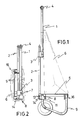
- Figure 1. It is a side elevational view with the framework and the bag unfolded in the position of use.
- Figure 2. It is a side view of the cart completely folded, in form of a bag.
- Figure 4. It is a front elevational view at the beginning of the folding operation or of the extension operation, indistinctly. Such as in the preceding figure really in an intermediate position both in the folding or in the extension.
- Figure 5. It is a perspective detail of the resistant base of the bag, from beneath, by the prismatic piece whereto the wheel frameworks are articulated, as well as the inner piece of the framework, which is taken apart.
- Figure 6. It is a plan view of the detail itself of the articulation prismatic piece which forms part of the resistant base of the bag.
- Figure 7.-It is the same perspective view as in Figure 5, wherein the lower piece of the framework is engaged in its articulation point, the lower piece and the framework carrying it being seen in a partial unfolded position. The wheel frame is folded in the resting position.
- Figure 8. It is a perspective view from the lower face, such as in the preceding figures, wherein the frame is unfolded and the lug of the lower piece has forced the wheel framework to be in the rolling position.
- Figure 9. It is a perspective view, also from beneath, wherein the frame is folded, the same as the wheel framework. This position corresponds to that of full folding in the form of a bag, such as represented in Figure 2.
- Figure 10. It represents three views of the prismatic piece of the lower ends of one of the seizing frameworks, according to other more improved embodiment.
- Figure 11.- It shows the perspective of said prismatic piece according to Figure 10.
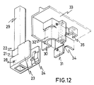
- Figure 12. It corresponds to the perspective view of the prismatic piece attached to the end of the framework, as well as the perspective of the zone of the rigid base which forms the framework of the bottom of the bag, wherein the prismatic piece articulation lodging is located, according to Figure 11.
- Figure 13 It represents a side elevational view of the prismatic piece according to Figure 10 attached to the framework, as well as the disposition in it of the tubular socket that joins them to the other displaceable framework, with their mutual fitting elements, in this improved way of embodiment.
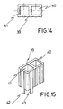
- Figure 14.- It is a plan view of the tubular socket according to the preceding figure.
- Figure 15.- It is a perspective view of the tubular socket.
- the frame 2 and the base 5 are joined to each other through the prismatic piece 7, which is provided with a lug 8 by means of which the extension of the wheel frameworks 9 and 10 is carried out, which wheels can be folded over the lower face of the rigid base 5.
- the prismatic piece 7 is articulated to the housing 11 of the rigid base 5 and its lug, 8, in the frames extension and folding movement, passes inside the zone 12 of the housing in order to attack the wheel frameworks 9 and 10, respectively.
- the wheel frameworks can be automatically unfolded by merely displacing both frames for their extension.
- the unfolded position of the frames can be maintained by means of retention elements situated either at the sleeves or in the housing that articulates the frames to the resistant plate of the bottom of the bag. In any case a solution tending to reinforce the retention system in the unfolded position will be advisable.
- the improvements provided by the invention are located in the housing articulated in one of the frames of the rigid base of the bag; in said rigid base and in the tubular socket that enables both seizing frameworks to slide in-between, and in the mechanism that fixes the positions of the frameworks and of the socket.
- said quadrangular prismatic piece 21 has a tubular extension 22. Two sides of the tubular extension are extended into parallel walls 23 and 24. Inside these walls, there are vertical opposing wedge-shaped embossings 25 and 26 and other quadrangular embossing 27, the base of which constitutes a stop.
- the anchoring axle not represented, is made to pass through the drilling 28 that goes through the lower part of the quadrangular piece towards one of the seizing frameworks.
- the axle itself, mounted in the drilling 28, goes through the walls 30 and 31 of the housing 32 which is formed at an edge of the rigid base 33.
- the housing 32 forms two recesses 34 and 35, parallel to each other, for the passage of walls 23 and 24 of the quadrangular piece.
- the lug or wall 23 has a higher flexibility index, for which purpose it has a smaller thickness than the other wall 24.
- the projection inside the lug 23 is intended to constitute the engagement on the end of said wall in order to fix the unfolded position of the framework and of the bag, when it is displaced in its assembly sliding inside the paths 34 and 35 provided at the platform.
- the projections 25 and 26 of the walls 23 and 24 have been conceived to retain the peripheral web 36 of the ferrule 37 whereinto the mobile frame 38 finishes.
- a one-single-piece double socket 39 forms two paths.
- the path 41 has some extensions 42 of the lower ends of its walls and the transversal grooves 43 which fit the web 36 of the ferrule 37 for retaining the frames in the extended position are formed in said walls.
- One of the extensions 42 just the corresponding one parallel to the frame 29, is provided with a semispherical embossing 44 that, in the extension position, fits the punching 45 of said frame.
- the seizing framework formed by two parallel frames, can be folded by sliding until the ferrule web fits the projections of the flexible wall of the quadrangular piece by which one of the frames is articulated to the rigid platform of the bag. Flexibility has been studied so that the ferrule can disengage itself with a slight pressure, but with no possibility of fortuitous uncoupling during handling.
Landscapes
- Engineering & Computer Science (AREA)
- Chemical & Material Sciences (AREA)
- Combustion & Propulsion (AREA)
- Transportation (AREA)
- Mechanical Engineering (AREA)
- Handcart (AREA)
Abstract
Description
- It is a foldable cart for shopping,of those having a wheeled framework to which the bottom of the bag is attached, which framework allows said wheels to be folded over the base, and the bag-framework assembly can be folded until forming a bag being seized by a part of the framework with which the cart is pulled in the unfolded position.
- According to the prior art, the wheels are welded to corresponding frameworks, articulated to a resistant base situated beneath the bottom of the bag, said frameworks being folded.
- In some cases, the bag handle is a doble one, formed by two "U"-tubes being parallelly displaced, which only aim is to be extended when the bag is pulled on fixed wheels or to withdraw in order to carry the bag hanging on the hand or on the arm. These cases correspond to non-foldable bags.
- Different types of frameworks allow their folding, together with the bag and the wheels, in order to convert the assembly into a bag or reduced size and carry it hanging on until the moment when shopping is done, at which moment the wheels are extended and unfolded so that the loaded bag leans thereon and transport is easier.
- The object of the invention is a foldable cart for buying, of the type of those being converted into a bag of reduced size, with the peculiarity that the bag and the wheels are automatically unfolded when one proceeds to extend both seizing frameworks, parallelly arranged, that it comprises.
- With that aim, one of the frameworks has been provided with points of junction over the high part of the bag and the other with angular plates at its articulation ends on the resistant plate of the bottom of the bag, by which the wheels frameworks are forced to unfold and which are retained in this position until proceeding on the contrary, i.e., until proceeding to reduce the height of the seizing frameworks and to fold the bag and the resistant base.
- At the side opposite that one whereto the seizing frameworks are articulated, the base is provided with two plates with notches for fitting under pressure against the frameworks, when the cart is folded.
- There are, at the parallel sleeves which are crossed by the seizing frameworks, for their extension and folding, retaining means so as to avoid an untimely folding.
- In a more improved embodiment of the invention, the retention means of the bag both in the folded and in the unfolded positions, can be improved without needing a great effort for changing position, being, however, sufficient to maintain the chosen position static.
- In this regard, the prismatic piece of the lower ends of one of the parallelly displacing seizing frameworks has a second lug, parallel to the first one and with a higher flexibility index than this one, so that, while the latter carries out the unfolding of the wheel frameworks, the former fits in in the working position of the resistant base. The latter is provided with two wide paths whereinto the ends of said framework articulate, so that the second lug passes through a guiding space, touching one of the walls and being sufficiently away from the opposite wall as to provide with the necessary room for the lateral movement of said lug, which lug is provided, at the surface that touches said wall, with a step which acts as an anchoring means on the upper edge of said path.
- The double tubular parallel sleeves are provided with a quadrangular passage of the same section as the sliding frameworks, thereby being able to eliminate lateral movements.
- On the other hand, one of the sockets of each pair is provided with axial projections, coincident with each face or facet, having inner notches, provided with flexibility, in which notches the peripheral web of a ferrule provided at the end of the frame not attached to the resistant base engages in the extension position of the parallel frames. Just this peripheral web constitutes the means by which the resistant base disengages the retaining lug through its penetration between the two ones with which the terminal or prismatic piece that relates it to the other frame is provided.
- For a better comprehension of the above description, the present specification has nine sheets of drawings attached thereto, wherein the cart assembly has been represented in different extension and folding positions, as well as details of the elements by which the extension and folding are attained.
- Figure 1.- It is a side elevational view with the framework and the bag unfolded in the position of use.
- Figure 2.- It is a side view of the cart completely folded, in form of a bag.
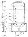
- Figure 3.- It is a side elevational detail at the beginning of the folding operation.
- Figure 4.- It is a front elevational view at the beginning of the folding operation or of the extension operation, indistinctly. Such as in the preceding figure really in an intermediate position both in the folding or in the extension.
- Figure 5.- It is a perspective detail of the resistant base of the bag, from beneath, by the prismatic piece whereto the wheel frameworks are articulated, as well as the inner piece of the framework, which is taken apart.
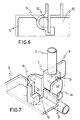
- Figure 6.- It is a plan view of the detail itself of the articulation prismatic piece which forms part of the resistant base of the bag.
- Figure 7.-It is the same perspective view as in Figure 5, wherein the lower piece of the framework is engaged in its articulation point, the lower piece and the framework carrying it being seen in a partial unfolded position. The wheel frame is folded in the resting position.
- Figure 8.- It is a perspective view from the lower face, such as in the preceding figures, wherein the frame is unfolded and the lug of the lower piece has forced the wheel framework to be in the rolling position.
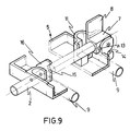
- Figure 9.- It is a perspective view, also from beneath, wherein the frame is folded, the same as the wheel framework. This position corresponds to that of full folding in the form of a bag, such as represented in Figure 2.
- Figure 10.- It represents three views of the prismatic piece of the lower ends of one of the seizing frameworks, according to other more improved embodiment.
- Figure 11.- It shows the perspective of said prismatic piece according to Figure 10.
- Figure 12.- It corresponds to the perspective view of the prismatic piece attached to the end of the framework, as well as the perspective of the zone of the rigid base which forms the framework of the bottom of the bag, wherein the prismatic piece articulation lodging is located, according to Figure 11.
- Figure 13.- It represents a side elevational view of the prismatic piece according to Figure 10 attached to the framework, as well as the disposition in it of the tubular socket that joins them to the other displaceable framework, with their mutual fitting elements, in this improved way of embodiment.
- Figure 14.- It is a plan view of the tubular socket according to the preceding figure.
- Figure 15.- It is a perspective view of the tubular socket.
- The elements constituting the cart for shopping have been numerically referenced for identification purposes.
- Thus, there are two
frames tubular sleeves 3 fixedly engaged to theframe 1 that constitutes theseizing handle 4 and which are sliding on theframe 2 being attached by the lower part to therigid base 5 of the bottom of thebag 6. - The
frame 2 and thebase 5 are joined to each other through theprismatic piece 7, which is provided with alug 8 by means of which the extension of thewheel frameworks rigid base 5. - The
prismatic piece 7 is articulated to thehousing 11 of therigid base 5 and its lug, 8, in the frames extension and folding movement, passes inside thezone 12 of the housing in order to attack thewheel frameworks - In the unfolding position (figures 5 and 8), the
pivot 13 of the prismatic piece fits into theslot 14 of the housing, as retaining element for the assembly. - In the same folding position (figure 9), the
frame 2 fits into thenotch 15 of thepiece 16. - By means of the herein described elements, the wheel frameworks can be automatically unfolded by merely displacing both frames for their extension.
- It has been foreseen that the unfolded position of the frames can be maintained by means of retention elements situated either at the sleeves or in the housing that articulates the frames to the resistant plate of the bottom of the bag. In any case a solution tending to reinforce the retention system in the unfolded position will be advisable.
- According to the most improved embodiment, as shown in figures 10 to 15, it is understood that the improvements provided by the invention are located in the housing articulated in one of the frames of the rigid base of the bag; in said rigid base and in the tubular socket that enables both seizing frameworks to slide in-between, and in the mechanism that fixes the positions of the frameworks and of the socket.
- In accordance with this, said quadrangular
prismatic piece 21 has atubular extension 22. Two sides of the tubular extension are extended intoparallel walls shaped embossings drilling 28 that goes through the lower part of the quadrangular piece towards one of the seizing frameworks. The axle itself, mounted in thedrilling 28, goes through thewalls 30 and 31 of thehousing 32 which is formed at an edge of therigid base 33. Thehousing 32 forms tworecesses walls wall 23 has a higher flexibility index, for which purpose it has a smaller thickness than theother wall 24. The projection inside thelug 23 is intended to constitute the engagement on the end of said wall in order to fix the unfolded position of the framework and of the bag, when it is displaced in its assembly sliding inside thepaths - The
projections walls peripheral web 36 of the ferrule 37 whereinto themobile frame 38 finishes. - A one-single-piece
double socket 39 forms two paths. The first one 40 for theframe 29 and the second one 41 for theframe 38. Both frames move along said paths of the socket in a parallel position. - The
path 41 has someextensions 42 of the lower ends of its walls and thetransversal grooves 43 which fit theweb 36 of the ferrule 37 for retaining the frames in the extended position are formed in said walls. - One of the
extensions 42, just the corresponding one parallel to theframe 29, is provided with asemispherical embossing 44 that, in the extension position, fits thepunching 45 of said frame. - It is inferred from the above description that the seizing framework, formed by two parallel frames, can be folded by sliding until the ferrule web fits the projections of the flexible wall of the quadrangular piece by which one of the frames is articulated to the rigid platform of the bag. Flexibility has been studied so that the ferrule can disengage itself with a slight pressure, but with no possibility of fortuitous uncoupling during handling.
- It happens the same in the coupling of the ferrule between the lugs of the double sockets, wherein it is retained in the unfolded position, until a certain force is exerted for the uncoupling thereof.
- With these characteristics, the folding and unfolding of the bag becomes simple and efficient.
Claims (7)
- A FOLDABLE CART FOR SHOPPING,of those having a rigid base whereat frameworks carrying each one of the two wheels on which the bag is supported in unfolded position for its transport are arranged, said frameworks allowing the wheels to be folded underneath the rigid base that gives form to the bottom of the bag, whilst the seizing frameworks can be extended and folded by parallel sliding, in order to allow their extension for pulling the cart, or be folded in the form of a bag of reduced size for its hand transport, characterized in that one of the parallelly displacing frameworks is attached to the upper zone of the bag, pulling it for its extension and/or folding, whilst the other one is provided, close to its articulation axle over the resistant base of the bag, with some plates or lugs which on rotating go through a slot provided in said base, thereby falling into the wheel framework, making said wheels be unfolded and retained in this position.
- A FOLDABLE CART FOR SHOPING,according to claim 1, characterized in that both parallel frameworks move along both parallel tubular sockets, joined to each other two by two, these sockets being provided with retaining elements for the ends of one of the frameworks in order to fix it in the unfolded position.
- A FOLDABLE CART FOR SHOPPING,according to claims 1 and 2, characterized in that the resistant plate that gives form to the bottom of the bag is provided, at points opposed those of articulation of the seizing frameworks, with two plates with notches by which they fit under pressure onto said seizing frameworks when the assembly is folded so as to be converted into a bag of reduced size.
- A FOLDABLE CART FOR SHOPPING,according to claim 1, characterized by providing the quadrangular piece of the lower ends of one of the seizing frameworks, with a second lug, parallel to the first one and having a higher flexibility index, having at its inner face a projection which, as it slides on assemblying on the wall of the path provided in the platform, constitutes an engagement on the end of said wall in order to fix the unfolded position of the framework and of the bag.
- A FOLDABLE CART FOR SHOPPING,according to claim 4, characterized by providing the two lugs of the quadrangular piece with an embossing, both embossings facing each other in order to establish a passage in-between for a ferrule with which the mobile frame of the seizing framework is provided, said ferrule having a peripheral web which determines, in the insertion between the lugs of the quadrangular piece, the separation and disengagement thereof that allows the assembly to be folded.
- A FOLDABLE CART FOR SHOPPING,according to claims 4 and 5, characterized in that the peripheral web of the ferrule is located, in the unfolded position of the assembly, between the lugs established as an extension of the double sockets which guide in-between the seizing frameworks, said lugs being provided, with that aim, with transversal notches.
- A FOLDABLE CART FOR SHOPPING,according to claims 4, 5 and 6, characterized in that one of the lugs extending from the double sockets is provided at the outer face coinciding with the position of the opposing framework with a semispherically-shaped embossing by which it is coupled in the unfolded situation of the seizing framework, into a punching foreseen in said opposing framework, thereby fixing the position thereof.
Priority Applications (1)
| Application Number | Priority Date | Filing Date | Title |
|---|---|---|---|
| AT88115000T ATE89792T1 (en) | 1988-06-28 | 1988-09-14 | FOLDABLE HANDCART FOR SHOPPING. |
Applications Claiming Priority (2)
| Application Number | Priority Date | Filing Date | Title |
|---|---|---|---|
| ES8802023A ES2011354A6 (en) | 1988-06-28 | 1988-06-28 | Foldable cart for shopping. |
| ES8802023 | 1988-06-28 |
Publications (3)
| Publication Number | Publication Date |
|---|---|
| EP0348552A2 EP0348552A2 (en) | 1990-01-03 |
| EP0348552A3 EP0348552A3 (en) | 1990-07-04 |
| EP0348552B1 true EP0348552B1 (en) | 1993-05-26 |
Family
ID=8257056
Family Applications (1)
| Application Number | Title | Priority Date | Filing Date |
|---|---|---|---|
| EP88115000A Expired - Lifetime EP0348552B1 (en) | 1988-06-28 | 1988-09-14 | Foldable cart for shopping |
Country Status (7)
| Country | Link |
|---|---|
| US (1) | US4989889A (en) |
| EP (1) | EP0348552B1 (en) |
| AT (1) | ATE89792T1 (en) |
| DE (1) | DE3881388T2 (en) |
| ES (1) | ES2011354A6 (en) |
| HK (1) | HK55995A (en) |
| MX (1) | MX172344B (en) |
Families Citing this family (37)
| Publication number | Priority date | Publication date | Assignee | Title |
|---|---|---|---|---|
| US5072958A (en) * | 1991-02-19 | 1991-12-17 | Young Horace J | Hand truck |
| US5348325A (en) * | 1991-10-11 | 1994-09-20 | Martin Abrams | Portable, collapsible luggage carrier |
| USD352145S (en) | 1992-10-15 | 1994-11-01 | Germans Server, S.L. | Shopping cart |
| ATE168335T1 (en) * | 1995-06-21 | 1998-08-15 | Moll Jaime Garcia | FOLDABLE SHOPPING CART |
| CN2241659Y (en) * | 1995-11-16 | 1996-12-04 | 孙勇 | Folding barrow with soft packing bag |
| US5649718A (en) * | 1996-08-01 | 1997-07-22 | Groglio; Valerie Defede | Utility cart |
| US5765702A (en) * | 1997-03-04 | 1998-06-16 | L&P Property Management Company | Wheeled merchandise display rack |
| US5863055A (en) * | 1997-09-03 | 1999-01-26 | Kasravi; Kasra | Personal cart |
| FR2770192A1 (en) | 1997-10-23 | 1999-04-30 | N3P Sa | Individual trolley for transporting merchandise |
| US6070899A (en) * | 1998-05-28 | 2000-06-06 | Gines; Roberto | Self-retracting cart for use in the cargo bay of a sport utility vehicle |
| US7458600B1 (en) * | 1998-12-09 | 2008-12-02 | Berke Joseph J | Cart and bag carrier |
| US6102433A (en) * | 1999-10-15 | 2000-08-15 | Stevens; Terence | Compact cart |
| ES1046485Y (en) * | 2000-06-02 | 2001-06-01 | Germans Server Sl | IMPROVED SHOPPING CART. |
| US6328329B1 (en) | 2000-06-20 | 2001-12-11 | William L. Smith | Collapsible shopping cart with removable mesh basket |
| US6491318B1 (en) * | 2000-08-29 | 2002-12-10 | Tamara Lyn Galt | Folding cart |
| US6378892B1 (en) * | 2000-09-22 | 2002-04-30 | Ben M. Hsia | Foldable stroller with detachable supplemental seat |
| RU2223191C2 (en) * | 2001-11-01 | 2004-02-10 | Александр Иванович Худолий | Hand truck |
| AU2002364546A1 (en) * | 2001-12-10 | 2003-06-23 | Darren J. Kady | Folding cart with bag |
| ES2237301B1 (en) * | 2003-09-01 | 2007-03-16 | Germans Server, S.L. | FOLDING CART FOR PURCHASE. |
| US20050140103A1 (en) * | 2003-12-30 | 2005-06-30 | Marchant Michael D. | Carrying bag for folding chair |
| US7140635B2 (en) * | 2004-05-18 | 2006-11-28 | Franzus Company Llc | Portable luggage carts/carriers |
| US7188859B2 (en) * | 2004-08-05 | 2007-03-13 | Hardin Kelly L | Shopping bag carrier |
| ES1058599Y (en) * | 2004-09-22 | 2005-04-16 | Germans Server Sl | SHOPPING CART. |
| RU2282549C1 (en) * | 2005-02-09 | 2006-08-27 | Александр Иванович Худолий | Hand truck |
| US20060198562A1 (en) * | 2005-03-04 | 2006-09-07 | California Innovations Inc. | Foldable insulated bag with trailing member |
| WO2007041770A1 (en) * | 2005-10-07 | 2007-04-19 | Maclaw No. 477 Pty Ltd | Foldable shopping bag with ground-engaging wheels |
| US7594669B2 (en) * | 2007-05-14 | 2009-09-29 | Linda Acosta | Halloween portable container |
| US20080309038A1 (en) * | 2007-06-14 | 2008-12-18 | James Gilligan | Trash bag holder and transporter |
| US20090039621A1 (en) * | 2007-08-06 | 2009-02-12 | Marjorie Parmenter | Foldable compact carry-all |
| USD642798S1 (en) * | 2008-04-09 | 2011-08-09 | Mccollum James D | Wheeled tote bag |
| USD599972S1 (en) | 2008-05-08 | 2009-09-08 | Jgr Copa, Llc | Convertible table and cargo cart |
| US7784816B2 (en) * | 2008-09-12 | 2010-08-31 | Jian Shikun | Flat platform cart with collapsible casters |
| US8544857B2 (en) * | 2009-09-30 | 2013-10-01 | Randy Schnarr | Foldable wheeled container |
| TWI542498B (en) * | 2013-11-05 | 2016-07-21 | Yee Shiuann Entpr Co Ltd | Trolley structure |
| US10160470B2 (en) | 2015-01-20 | 2018-12-25 | Nancy K. N. Unrath | Market trolley |
| CN115046117A (en) * | 2022-06-28 | 2022-09-13 | 苏州德锐朗智能科技有限公司 | Folding type roller device of power generation equipment |
| CN114962940A (en) * | 2022-06-28 | 2022-08-30 | 苏州德锐朗智能科技有限公司 | A folding roller device with supporting feet |
Family Cites Families (12)
| Publication number | Priority date | Publication date | Assignee | Title |
|---|---|---|---|---|
| FR1488011A (en) * | 1965-07-29 | 1967-07-07 | Improvements to hand trucks and similar rolling vehicles | |
| US3348857A (en) * | 1965-12-03 | 1967-10-24 | Rollin Libby | Convertible two-wheeled carrier |
| GB1126122A (en) * | 1966-07-09 | 1968-09-05 | Albert Norman Hadley | Shopping trolley |
| GB1145447A (en) * | 1967-03-01 | 1969-03-12 | John Dennis Clegg | Improvements relating to wheeled carriers for use by pedestrian shoppers |
| US4335895A (en) * | 1979-08-02 | 1982-06-22 | Brooks Walker | Wheeled carrier for suitcases and the like |
| GB2111917A (en) * | 1981-07-16 | 1983-07-13 | Angus Christopher Firth | Trolley |
| US4448434A (en) * | 1981-12-30 | 1984-05-15 | Anderson Milan B | Collapsible hand truck |
| US4458914A (en) * | 1982-11-22 | 1984-07-10 | Holtz Gilbert J | Luggage cart |
| US4570958A (en) * | 1984-06-13 | 1986-02-18 | Brooks Walker | Carrier for suitcases, luggage, garment bags, and the like |
| FR2567470B1 (en) * | 1984-07-12 | 1987-01-30 | Ampafrance | FOLDING TROLLEY |
| US4554034A (en) * | 1984-11-15 | 1985-11-19 | Battelle Memorial Institute | Bonding capsules |
| US4754985A (en) * | 1986-10-20 | 1988-07-05 | Im Byung Do | Luggage carrier |
-
1988
- 1988-06-28 ES ES8802023A patent/ES2011354A6/en not_active Expired - Lifetime
- 1988-09-14 EP EP88115000A patent/EP0348552B1/en not_active Expired - Lifetime
- 1988-09-14 DE DE8888115000T patent/DE3881388T2/en not_active Expired - Fee Related
- 1988-09-14 AT AT88115000T patent/ATE89792T1/en active
-
1989
- 1989-01-10 US US07/295,747 patent/US4989889A/en not_active Expired - Lifetime
- 1989-03-01 MX MX015118A patent/MX172344B/en unknown
-
1995
- 1995-04-11 HK HK55995A patent/HK55995A/en not_active IP Right Cessation
Also Published As
| Publication number | Publication date |
|---|---|
| DE3881388D1 (en) | 1993-07-01 |
| MX172344B (en) | 1993-12-13 |
| EP0348552A2 (en) | 1990-01-03 |
| ES2011354A6 (en) | 1990-01-01 |
| HK55995A (en) | 1995-04-21 |
| DE3881388T2 (en) | 1993-09-09 |
| ATE89792T1 (en) | 1993-06-15 |
| US4989889A (en) | 1991-02-05 |
| EP0348552A3 (en) | 1990-07-04 |
Similar Documents
| Publication | Publication Date | Title |
|---|---|---|
| EP0348552B1 (en) | Foldable cart for shopping | |
| US5613696A (en) | Shopping trolley for supermarkets and the like | |
| US6336234B1 (en) | Bottom frame structure for playpen | |
| GB2214903A (en) | Collapsible container | |
| JP3963279B2 (en) | Transport and storage containers | |
| US11375788B2 (en) | Luggage with support | |
| US5718444A (en) | Folding collapsible stroller | |
| AU741452C (en) | Folding stage | |
| US5207333A (en) | Multi-storied parking/displaying rack | |
| CA2948454A1 (en) | Carrier having foldable wheels | |
| KR200488592Y1 (en) | Cart | |
| EP1288101A1 (en) | Stroller foldable in three | |
| KR20060044510A (en) | stroller | |
| US2847227A (en) | Collapsible hamper cart | |
| GB2156747A (en) | Baby carriage grip rod locking mechanism | |
| EP1593324B1 (en) | Bed rail assembly | |
| JPH06286752A (en) | Folding trolley that doubles as a box | |
| CN1325335C (en) | Foldable container | |
| KR102078726B1 (en) | Apparatus for unfolding foldable display device | |
| EP1323614A1 (en) | Collapsible infant stroller | |
| JP7459323B2 (en) | Furniture and furniture parts assembly | |
| KR200263363Y1 (en) | The Handcart for Transporting Things | |
| US6017052A (en) | Folding collapsible frame assembly for a golf cart | |
| KR200221306Y1 (en) | Collapsible display stand | |
| JP3020116U (en) | Folding wagon |
Legal Events
| Date | Code | Title | Description |
|---|---|---|---|
| PUAI | Public reference made under article 153(3) epc to a published international application that has entered the european phase |
Free format text: ORIGINAL CODE: 0009012 |
|
| AK | Designated contracting states |
Kind code of ref document: A2 Designated state(s): AT BE CH DE FR GB GR IT LI LU NL SE |
|
| PUAL | Search report despatched |
Free format text: ORIGINAL CODE: 0009013 |
|
| AK | Designated contracting states |
Kind code of ref document: A3 Designated state(s): AT BE CH DE FR GB GR IT LI LU NL SE |
|
| 17P | Request for examination filed |
Effective date: 19901130 |
|
| 17Q | First examination report despatched |
Effective date: 19920812 |
|
| GRAA | (expected) grant |
Free format text: ORIGINAL CODE: 0009210 |
|
| AK | Designated contracting states |
Kind code of ref document: B1 Designated state(s): AT BE CH DE FR GB GR IT LI LU NL SE |
|
| PG25 | Lapsed in a contracting state [announced via postgrant information from national office to epo] |
Ref country code: SE Effective date: 19930526 Ref country code: GR Free format text: LAPSE BECAUSE OF FAILURE TO SUBMIT A TRANSLATION OF THE DESCRIPTION OR TO PAY THE FEE WITHIN THE PRESCRIBED TIME-LIMIT Effective date: 19930526 Ref country code: AT Effective date: 19930526 |
|
| REF | Corresponds to: |
Ref document number: 89792 Country of ref document: AT Date of ref document: 19930615 Kind code of ref document: T |
|
| REF | Corresponds to: |
Ref document number: 3881388 Country of ref document: DE Date of ref document: 19930701 |
|
| ITF | It: translation for a ep patent filed | ||
| ET | Fr: translation filed | ||
| EPTA | Lu: last paid annual fee | ||
| PLBE | No opposition filed within time limit |
Free format text: ORIGINAL CODE: 0009261 |
|
| STAA | Information on the status of an ep patent application or granted ep patent |
Free format text: STATUS: NO OPPOSITION FILED WITHIN TIME LIMIT |
|
| 26N | No opposition filed | ||
| REG | Reference to a national code |
Ref country code: CH Ref legal event code: PUE Owner name: GERMANS SERVER, S.L. |
|
| REG | Reference to a national code |
Ref country code: GB Ref legal event code: 732E |
|
| REG | Reference to a national code |
Ref country code: FR Ref legal event code: TP |
|
| NLS | Nl: assignments of ep-patents |
Owner name: GERMANS SERVER, S.L. TE PEDREGUER, SPANJE. |
|
| ITPR | It: changes in ownership of a european patent |
Owner name: CESSIONE;GERMANS SERVER S.L. |
|
| PGFP | Annual fee paid to national office [announced via postgrant information from national office to epo] |
Ref country code: LU Payment date: 19950901 Year of fee payment: 8 |
|
| PGFP | Annual fee paid to national office [announced via postgrant information from national office to epo] |
Ref country code: CH Payment date: 19950928 Year of fee payment: 8 |
|
| PGFP | Annual fee paid to national office [announced via postgrant information from national office to epo] |
Ref country code: NL Payment date: 19950929 Year of fee payment: 8 |
|
| PG25 | Lapsed in a contracting state [announced via postgrant information from national office to epo] |
Ref country code: LU Free format text: LAPSE BECAUSE OF NON-PAYMENT OF DUE FEES Effective date: 19960914 |
|
| PG25 | Lapsed in a contracting state [announced via postgrant information from national office to epo] |
Ref country code: LI Effective date: 19960930 Ref country code: CH Effective date: 19960930 |
|
| PG25 | Lapsed in a contracting state [announced via postgrant information from national office to epo] |
Ref country code: NL Effective date: 19970401 |
|
| REG | Reference to a national code |
Ref country code: CH Ref legal event code: PL |
|
| NLV4 | Nl: lapsed or anulled due to non-payment of the annual fee |
Effective date: 19970401 |
|
| REG | Reference to a national code |
Ref country code: FR Ref legal event code: CL |
|
| REG | Reference to a national code |
Ref country code: GB Ref legal event code: IF02 |
|
| PGFP | Annual fee paid to national office [announced via postgrant information from national office to epo] |
Ref country code: BE Payment date: 20020719 Year of fee payment: 15 |
|
| PGFP | Annual fee paid to national office [announced via postgrant information from national office to epo] |
Ref country code: GB Payment date: 20020911 Year of fee payment: 15 |
|
| PGFP | Annual fee paid to national office [announced via postgrant information from national office to epo] |
Ref country code: DE Payment date: 20020926 Year of fee payment: 15 |
|
| PG25 | Lapsed in a contracting state [announced via postgrant information from national office to epo] |
Ref country code: GB Free format text: LAPSE BECAUSE OF NON-PAYMENT OF DUE FEES Effective date: 20030914 |
|
| PG25 | Lapsed in a contracting state [announced via postgrant information from national office to epo] |
Ref country code: BE Free format text: LAPSE BECAUSE OF NON-PAYMENT OF DUE FEES Effective date: 20030930 |
|
| BERE | Be: lapsed |
Owner name: *GERMANS SERVER S.L. Effective date: 20030930 |
|
| PG25 | Lapsed in a contracting state [announced via postgrant information from national office to epo] |
Ref country code: DE Free format text: LAPSE BECAUSE OF NON-PAYMENT OF DUE FEES Effective date: 20040401 |
|
| GBPC | Gb: european patent ceased through non-payment of renewal fee |
Effective date: 20030914 |
|
| PG25 | Lapsed in a contracting state [announced via postgrant information from national office to epo] |
Ref country code: IT Free format text: LAPSE BECAUSE OF NON-PAYMENT OF DUE FEES Effective date: 20050914 |
|
| PGFP | Annual fee paid to national office [announced via postgrant information from national office to epo] |
Ref country code: FR Payment date: 20070629 Year of fee payment: 20 |