EP0348084A1 - Data conversion circuit for well logging system - Google Patents
Data conversion circuit for well logging system Download PDFInfo
- Publication number
- EP0348084A1 EP0348084A1 EP89305888A EP89305888A EP0348084A1 EP 0348084 A1 EP0348084 A1 EP 0348084A1 EP 89305888 A EP89305888 A EP 89305888A EP 89305888 A EP89305888 A EP 89305888A EP 0348084 A1 EP0348084 A1 EP 0348084A1
- Authority
- EP
- European Patent Office
- Prior art keywords
- signal
- output
- converter
- amplifier
- sonde
- Prior art date
- Legal status (The legal status is an assumption and is not a legal conclusion. Google has not performed a legal analysis and makes no representation as to the accuracy of the status listed.)
- Withdrawn
Links
- 238000006243 chemical reaction Methods 0.000 title claims abstract description 28
- 239000000872 buffer Substances 0.000 claims abstract description 21
- 230000015572 biosynthetic process Effects 0.000 claims abstract description 8
- 238000005755 formation reaction Methods 0.000 claims abstract description 8
- 238000005259 measurement Methods 0.000 claims abstract description 6
- 230000003321 amplification Effects 0.000 claims abstract description 3
- 238000003199 nucleic acid amplification method Methods 0.000 claims abstract description 3
- 230000001105 regulatory effect Effects 0.000 claims abstract description 3
- 239000004020 conductor Substances 0.000 claims description 27
- 239000003990 capacitor Substances 0.000 claims description 7
- 230000005540 biological transmission Effects 0.000 claims description 2
- 238000002955 isolation Methods 0.000 claims description 2
- 230000002596 correlated effect Effects 0.000 claims 1
- 238000010586 diagram Methods 0.000 description 1
- 230000009977 dual effect Effects 0.000 description 1
- 230000000977 initiatory effect Effects 0.000 description 1
- 230000001788 irregular Effects 0.000 description 1
- 238000000034 method Methods 0.000 description 1
- 230000000737 periodic effect Effects 0.000 description 1
- 230000000630 rising effect Effects 0.000 description 1
- 238000005070 sampling Methods 0.000 description 1
- 230000035939 shock Effects 0.000 description 1
- 238000001228 spectrum Methods 0.000 description 1
Images
Classifications
-
- E—FIXED CONSTRUCTIONS
- E21—EARTH OR ROCK DRILLING; MINING
- E21B—EARTH OR ROCK DRILLING; OBTAINING OIL, GAS, WATER, SOLUBLE OR MELTABLE MATERIALS OR A SLURRY OF MINERALS FROM WELLS
- E21B49/00—Testing the nature of borehole walls; Formation testing; Methods or apparatus for obtaining samples of soil or well fluids, specially adapted to earth drilling or wells
-
- E—FIXED CONSTRUCTIONS
- E21—EARTH OR ROCK DRILLING; MINING
- E21B—EARTH OR ROCK DRILLING; OBTAINING OIL, GAS, WATER, SOLUBLE OR MELTABLE MATERIALS OR A SLURRY OF MINERALS FROM WELLS
- E21B47/00—Survey of boreholes or wells
- E21B47/12—Means for transmitting measuring-signals or control signals from the well to the surface, or from the surface to the well, e.g. for logging while drilling
-
- G—PHYSICS
- G01—MEASURING; TESTING
- G01V—GEOPHYSICS; GRAVITATIONAL MEASUREMENTS; DETECTING MASSES OR OBJECTS; TAGS
- G01V5/00—Prospecting or detecting by the use of ionising radiation, e.g. of natural or induced radioactivity
- G01V5/04—Prospecting or detecting by the use of ionising radiation, e.g. of natural or induced radioactivity specially adapted for well-logging
- G01V5/045—Transmitting data to recording or processing apparatus; Recording data
Definitions
- This invention relates to a data conversion circuit for use in well logging.
- a logging sonde having a pulsed neutron source is lowered on a cable into a well to provide periodic bursts of neutrons into the immediate formations.
- the response of the formations is measured by observation of a scintillation counter or photomultiplier tube (PMT).
- the formation response has the form of a number of close nuclear events of irregular spacing, but typically is an avalanche of pulses where pulse energy level varies over a relatively wide range.
- This provides an output signal from a typical PMT which is a plurality of pulses of variant height.
- the pulses occur so rapidly that it is difficult to obtain a count of the pulses as well as pulse height measurements.
- these measurements must be accomplished in a logging tool which is lowered in downhole circumstances, exposed to extremely high temperatures and subjected to shock loading as the sonde is retrieved from the well.
- a data conversion circuit apparatus for use in a downhole logging tool in a sonde for making measurements of nuclear events occasioned by logging formations adjacent a well borehole, wherein the nuclear events have variable frequency and amplitude and such nuclear events are measured by a measuring means which forms a measured signal, wherein said data conversion circuit comprises:
- the converter is adapted to form an output of N digits on N digit conductors and also an output handshake signal for a sonde-located telemetry system to prompt said telemetry system for data transmission along the logging cable supporting said sonde in a well borehole.
- the circuit may advantageously include an enabling clamp means connected to the output of said amplifier means and to the input of said A/D converter and having an enabled input preventing clamping of an input analog signal to said A/D converter.
- the circuit may also with advantage include an input unity gain buffer amplifier connected to said input circuit having a high input impedance for providing isolation to the measured voltage source.
- the circuit includes a sample and hold switch driving said buffer amplifier with
- control means includes means responsive to said peak current timing signal forming a latching signal holding said control means in the operated condition until receipt of an end of conversion signal from said A/D converter.
- the invention also includes a sonde having a data conversion circuit of the invention installed therein.
- the numeral 10 identifies a sonde which is lowered into a cased well 11 supported on a logging cable 12.
- the sonde encloses a telemetry system 13 to transmit data to the surface; as needed, the cable transmits instructions for operation of the sonde.
- a pulsed neutron source 14 is likewise included in the sonde.
- a PMT 15 located in the sonde responds after the burst of neutrons which irradiate the adjacent formations. On irradiation, an avalanche of nuclear events is observed in the PMT which provides an output signal for handling by the present circuit.
- the logging cable 12 passes over a sheave 16 and is stored on a drum 17.
- the logging cable provides signals on insulated conductors in the cable to a CPU 18.
- the CPU forms signals which are recorded on a recorder as a function of depth.
- the recorder is connected by suitable mechanical or electrical measuring means 19 to sheave 16 so that the data from the CPU 18 are recorded as a function of depth in the well 11.
- the numeral 20 identifies the exemplary circuit of the invention. It is comprised of several major segments. The first major segment is located within the dotted line 21 and is described as a voltage pulse peak detector. It cooperates with the other components, namely a voltage pulse amplifier 26, a base line restoring circuit 22, a peak sample and hold circuit 23, an A/D converter 24 and an output buffer register 25 shown as two circuit components.
- the output of the PMT 15 is supplied through a typical pre-amp 28 and then is input to a MOSFET high impedance input circuit Q2.
- the input signal is applied to the gate of a first MOSFET forming an output across a voltage follower and thus has unity gain.
- the circuit incorporating Q2, R27, R28, C36, C37 and C38 forms an output on a conductor 30.
- This output signal is applied to a pair of circuits at AR3 and AR4, a peak detector and threshold voltage discriminator respectively.
- the circuit AR4 which incorporates additional components R20, R22, R23, R24, R26, C28, C29, C30 and C31 sets a threshold above which signals are detected. Pulses which do not rise to this threshold are ignored by the system.
- the output of the amplifier AR4 enables the peak detector AR3 to recognize only pulses of a certain amplitude or greater.
- the signal on the conductor 30 is input to pins 4 and 5 of the amplifier AR3.
- the circuit AR3 includes components C27, C32, C33, C34, R21 and R25. Components R21 and C34 operate as an integrator circuit. So long as the input voltage on the conductor is rising, the input at pin 5 increases more rapidly than the input at pin 4. When the voltage peaks and begins to decrease, this provides a voltage reversal at the pins 4 and 5.
- the output of AR3 at pin 14 goes from high to low on conductor 31 to provide a switching signal which causes the sample and hold circuit 23 to switch from sampling to hold and also starts the analog-to-digital conversion occurring in the circuit 24.
- a conductor 32 provides the enable signal for the amplifier AR3.
- the pulse amplifier AR1 incorporates components C22, C24, C25, R14, R15, R16, R18, R19, R13, C15 and CR1.
- This circuit is an amplifier providing an inverted output.
- the differential signal formed between the input at pins 4 and 5 is controlled by the output of the base restorer circuit supplied over the conductor 33 from the amplifier AR2.
- the output pulse is sharpened by the diode CR1 and R15 which function as a clamp at about 0.6 volts below ground when the output is unloaded and free to drift to the switching circuit to be described.
- the conductor 33 provides the restored baseline value for AR1 from AR2.
- the baseline restorer includes the amplifier AR2 and also C19, C20, C21, C23, C26 and R17.
- This system is an inverting voltage integrating circuit which responds to the average DC level at the input pin 4 and forms a correction voltage for the conductor 33.
- the feedback loop around AR2 incorporates the capacitor C20 to establish the reference or baseline value.
- the output of the amplifier AR1 is supplied on the conductor 34 for a switching circuit to be described.
- the conductor 35 delivers the amplified analog value from Q1 to pin 4 of AR1 as a feedback signal for AR1 for its operation.
- Operation of this circuit revolves around operation of the analog voltage switch U6, the voltage hold capacitor C14 connected to the output of that switch, a voltage buffer including the dual MOSFET unity gain buffer Q1, and control established by the flip flops FF1, FF2, FF3 and the several gates to be described.
- Operation of the circuit 23 involves the following actions. Assume that the peak detector circuit 21 senses a signal above the preset level. In that event, pin 14 of AR3 goes low to form a signal on the conductor 31 applied to an AND gate 36. Assume that the Q output of FF3 is low so that the AND gate 36 is enabled, forming a high output. This provides a start signal on the conductor 37 to the A/D 24. This starts analog-to-digital conversion.
- the signal on the conductor 31 remains low for a short period, and it ultimately reverts to a high level. When this occurs, the signal is coupled through the AND gate 36 and an inverter gate 38. Output goes high on the conductor 39.
- the signal on the conductor 39 is a clock pulse for FF2 which is a control flip flop providing a control signal for the switch U6.
- the FF2 output is on the conductor 40 and is denoted as the HS signal for the hold sample indication.
- the HS signal goes high, thereby opening the analog switch U6.
- the sample peak voltage is held constant at the analog switch hold capacitor C14.
- the voltage on that capacitor is supplied to pin 27 on the conductor 41 through the voltage buffer Q1.
- Q1 is a buffer amplifier with a gain of one.
- the input voltage applied to the input of Q1 is seen on conductor 41 and input to the A/D converter 24.
- the switch U6 selects the voltage on the hold capacitor C14 when U6 is open or the AR1 output when U6 is closed. It should be understood that subsequently occurring spectrum pulses should not be permitted to restart the analog-to-digital conversion. This is accomplished by utilizing the Q ⁇ . Output from pin 8 of FF2 applied to the set terminal of FF3, altering the Q output of FF3 at pin 5 which disables the AND gate 36. This interlock coupled through the start conductor 39 holds until the analog conversion has been completed.
- the A/D 24 provides an output on pin 20 which goes low to form an end of conversion (EOC) signal on the conductor 44.
- EOC end of conversion
- the EOC signal provides a positive going or high signal through the inverter gate 45 providing a clock pulse for FF1.
- the FF1 is thus operated and forms a high signal on the Q ⁇ , the high signal being provided on a conductor 46 which indicates that data is ready. This is input to the buffers 25 to cause such register buffers 25 to latch the values in the buffers.
- This signal is used in the system to initiate a handshake, with a downhole telemetry microprocessor asserting that data is available through the 8 bit digital output from the two buffers 25 to the telemetry microprocessor system.
- a return signal is received from the telemetry microprocessor on the conductor 48 which is the end of the transfer or the termination of the handshake from the telemetry microprocessor. This is input on the conductor 48. It is provided to terminal 3 of FF3 which breaks the routing just described. This indicates that the next peak can be prepared for measurement.
- the A/D 24 provides multiple bit digitation to the output buffers 25 which in turn provide the 8 bits of data digital output for the telemetry microprocessor.
- Additional signals are provided from the telemetry system microprocessor.
- One is a release signal and another output from the telemetry microprocessor circuit is a count overflow signal. These are both input to an OR gate 50. While these may not occur often, should they occur, the gate 50 provides an input to the FF1 which interrupts operation until the two signals are removed.
- Another input from the telemetry microprocessor is OE ⁇ , an enable signal for the buffers 25 to operate.
Landscapes
- Engineering & Computer Science (AREA)
- Life Sciences & Earth Sciences (AREA)
- Physics & Mathematics (AREA)
- Mining & Mineral Resources (AREA)
- Geology (AREA)
- General Life Sciences & Earth Sciences (AREA)
- Fluid Mechanics (AREA)
- Environmental & Geological Engineering (AREA)
- Geochemistry & Mineralogy (AREA)
- Geophysics (AREA)
- Remote Sensing (AREA)
- High Energy & Nuclear Physics (AREA)
- General Physics & Mathematics (AREA)
- Geophysics And Detection Of Objects (AREA)
Abstract
A data conversion circuit apparatus (20) for use in a downhole logging tool in a sonde (10) for making measurements of nuclear events occasioned by logging formations adjacent a well borehole (11), wherein the nuclear events have variable frequency and amplitude and such nuclear events are measured by a measuring means which forms a measured signal, wherein said data conversion circuit comprises:
- (a) an input circuit for receiving the measured signal which represents the nuclear events, said input circuit including:
- (1) threshold voltage determining means selecting a threshold voltage for the measured signal below which value the input circuit forms no response;
- (2) peak time determining means responsive to dynamic reversal and subsequent reduction in the measured signal from a larger value to a smaller value, said peak time determining means forming a peak occurrence timing signal indicative of such dynamic reversal above the threshold value by said threshold value determining means;
- (b) amplifier means connected to the measured signal for forming an amplified output signal;
- (c) base line restoring circuit means connected to said amplifier means for obtaining a regulated baseline value above which amplification by said amplifier means occurs;
- (d) an A/D converter having an analog input connected to said amplifier means for receiving the amplified signal therefrom;
- (e) output buffer register means connected to said A/D converter for providing a multi-bit representation of the measured signal through said amplifier means; and
- (f) control means responsive to said peak occurrence timing signal for forming a control signal supplied to said A/D converter to initiate operation thereof wherein operation continues to thereby provide conversion and outputting of digital representation to said buffer means, and further wherein said A/D converter forms an end of conversion signal output therefrom to said control means to enable said control means to initiate the next conversion.
Description
- This invention relates to a data conversion circuit for use in well logging.
- In certain well logging procedures, a logging sonde having a pulsed neutron source is lowered on a cable into a well to provide periodic bursts of neutrons into the immediate formations. The response of the formations is measured by observation of a scintillation counter or photomultiplier tube (PMT). The formation response has the form of a number of close nuclear events of irregular spacing, but typically is an avalanche of pulses where pulse energy level varies over a relatively wide range. This provides an output signal from a typical PMT which is a plurality of pulses of variant height. The pulses occur so rapidly that it is difficult to obtain a count of the pulses as well as pulse height measurements. Moreover, these measurements must be accomplished in a logging tool which is lowered in downhole circumstances, exposed to extremely high temperatures and subjected to shock loading as the sonde is retrieved from the well.
- We have now devised a data conversion circuit which provides a pulse height measuring system which digitizes the variable energy nuclear events, provides a digitized measure thereof, and which operates at sufficient speed that the consequential burst of nuclear events can be measured.
- According to the present invention, there is provided a data conversion circuit apparatus for use in a downhole logging tool in a sonde for making measurements of nuclear events occasioned by logging formations adjacent a well borehole, wherein the nuclear events have variable frequency and amplitude and such nuclear events are measured by a measuring means which forms a measured signal, wherein said data conversion circuit comprises:
- (a) an input circuit for receiving the measured signal which represents the nuclear events, said input circuit including:
- (1) threshold voltage determining means selecting a threshold voltage for the measured signal below which value the input circuit forms no response;
- (2) peak time determining means responsive to dynamic reversal and subsequent reduction in the measured signal from a larger value to a smaller value, said peak time determining means forming a peak occurrence timing signal indicative of such dynamic reversal above the threshold value by said threshold value determining means;
- (b) amplifier means connected to the measured signal for forming an amplified output signal;
- (c) base line restoring circuit means connected to said amplifier means for obtaining a regulated baseline value above which amplification by said amplifier means occurs;
- (d) an A/D converter having an analog input connected to said amplifier means for receiving the amplified signal therefrom;
- (e) output buffer register means connected to said A/D converter for providing a multi-bit representation of the measured signal through said amplifier means; and
- (f) control means responsive to said peak occurrence timing signal for forming a control signal supplied to said A/D converter to initiate operation thereof wherein operation continues to thereby provide conversion and outputting of digital representation to said buffer means, and further wherein said A/D converter forms an end of conversion signal output therefrom to said control means to enable said control means to initiate the next conversion.
- Preferably, the converter is adapted to form an output of N digits on N digit conductors and also an output handshake signal for a sonde-located telemetry system to prompt said telemetry system for data transmission along the logging cable supporting said sonde in a well borehole.
- The circuit may advantageously include an enabling clamp means connected to the output of said amplifier means and to the input of said A/D converter and having an enabled input preventing clamping of an input analog signal to said A/D converter. The circuit may also with advantage include an input unity gain buffer amplifier connected to said input circuit having a high input impedance for providing isolation to the measured voltage source.
- In one preferred arrangement, the circuit includes a sample and hold switch driving said buffer amplifier with
- (1) said amplified output signal; or
- (2) a nonvariant hold signal wherein said switch is switched to hold by said control means, and wherein said apparatus preferably further includes a hold capacitor connected to the output of said switch for providing a variable voltage responding to variations in said amplified output signal until said switch operates to a hold signal for a hold interval determined by said control means. Such a circuit may also include clamping means connected to the output of said amplifier means to limit amplified output to a specified voltage level.
- In another preferred arrangement, the control means includes means responsive to said peak current timing signal forming a latching signal holding said control means in the operated condition until receipt of an end of conversion signal from said A/D converter.
- The invention also includes a sonde having a data conversion circuit of the invention installed therein.
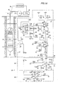
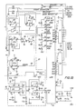
- In order that the invention may be more fully understood, one embodiment thereof will now be described, by way of example only, with reference to the accompanying Figures 1A and 1B which show a schematic wiring diagram of a circuit of the present invention installed in a sonde.
- In a single drawing, the
numeral 10 identifies a sonde which is lowered into a cased well 11 supported on alogging cable 12. The sonde encloses atelemetry system 13 to transmit data to the surface; as needed, the cable transmits instructions for operation of the sonde. Apulsed neutron source 14 is likewise included in the sonde. APMT 15 located in the sonde responds after the burst of neutrons which irradiate the adjacent formations. On irradiation, an avalanche of nuclear events is observed in the PMT which provides an output signal for handling by the present circuit. There may be more than one PMT in the sonde, and in that instance, duplicate sets of equipment can be provided. Thelogging cable 12 passes over asheave 16 and is stored on adrum 17. The logging cable provides signals on insulated conductors in the cable to aCPU 18. The CPU forms signals which are recorded on a recorder as a function of depth. The recorder is connected by suitable mechanical or electrical measuring means 19 to sheave 16 so that the data from theCPU 18 are recorded as a function of depth in thewell 11. - The
numeral 20 identifies the exemplary circuit of the invention. It is comprised of several major segments. The first major segment is located within thedotted line 21 and is described as a voltage pulse peak detector. It cooperates with the other components, namely avoltage pulse amplifier 26, a base line restoring circuit 22, a peak sample and holdcircuit 23, an A/D converter 24 and anoutput buffer register 25 shown as two circuit components. - The output of the
PMT 15 is supplied through a typical pre-amp 28 and then is input to a MOSFET high impedance input circuit Q2. As will be observed, the input signal is applied to the gate of a first MOSFET forming an output across a voltage follower and thus has unity gain. The circuit incorporating Q2, R27, R28, C36, C37 and C38 forms an output on aconductor 30. This output signal is applied to a pair of circuits at AR3 and AR4, a peak detector and threshold voltage discriminator respectively. The circuit AR4 which incorporates additional components R20, R22, R23, R24, R26, C28, C29, C30 and C31 sets a threshold above which signals are detected. Pulses which do not rise to this threshold are ignored by the system. Thus, the output of the amplifier AR4 enables the peak detector AR3 to recognize only pulses of a certain amplitude or greater. The signal on theconductor 30 is input topins pin 5 increases more rapidly than the input atpin 4. When the voltage peaks and begins to decrease, this provides a voltage reversal at thepins pin 14 goes from high to low onconductor 31 to provide a switching signal which causes the sample and holdcircuit 23 to switch from sampling to hold and also starts the analog-to-digital conversion occurring in thecircuit 24. Aconductor 32 provides the enable signal for the amplifier AR3. - The pulse amplifier AR1 incorporates components C22, C24, C25, R14, R15, R16, R18, R19, R13, C15 and CR1. This circuit is an amplifier providing an inverted output. The differential signal formed between the input at
pins conductor 33 from the amplifier AR2. The output pulse is sharpened by the diode CR1 and R15 which function as a clamp at about 0.6 volts below ground when the output is unloaded and free to drift to the switching circuit to be described. Theconductor 33 provides the restored baseline value for AR1 from AR2. The baseline restorer includes the amplifier AR2 and also C19, C20, C21, C23, C26 and R17. This system is an inverting voltage integrating circuit which responds to the average DC level at theinput pin 4 and forms a correction voltage for theconductor 33. The feedback loop around AR2 incorporates the capacitor C20 to establish the reference or baseline value. The output of the amplifier AR1 is supplied on theconductor 34 for a switching circuit to be described. Theconductor 35 delivers the amplified analog value from Q1 topin 4 of AR1 as a feedback signal for AR1 for its operation. - Operation of this circuit revolves around operation of the analog voltage switch U6, the voltage hold capacitor C14 connected to the output of that switch, a voltage buffer including the dual MOSFET unity gain buffer Q1, and control established by the flip flops FF1, FF2, FF3 and the several gates to be described. Operation of the
circuit 23 involves the following actions. Assume that thepeak detector circuit 21 senses a signal above the preset level. In that event, pin 14 of AR3 goes low to form a signal on theconductor 31 applied to an ANDgate 36. Assume that the Q output of FF3 is low so that the ANDgate 36 is enabled, forming a high output. This provides a start signal on theconductor 37 to the A/D 24. This starts analog-to-digital conversion. The signal on theconductor 31 remains low for a short period, and it ultimately reverts to a high level. When this occurs, the signal is coupled through the ANDgate 36 and aninverter gate 38. Output goes high on theconductor 39. The signal on theconductor 39 is a clock pulse for FF2 which is a control flip flop providing a control signal for the switch U6. The FF2 output is on theconductor 40 and is denoted as the HS signal for the hold sample indication. The HS signal goes high, thereby opening the analog switch U6. In turn, the sample peak voltage is held constant at the analog switch hold capacitor C14. The voltage on that capacitor is supplied to pin 27 on theconductor 41 through the voltage buffer Q1. Q1 is a buffer amplifier with a gain of one. The input voltage applied to the input of Q1 is seen onconductor 41 and input to the A/D converter 24. The switch U6 selects the voltage on the hold capacitor C14 when U6 is open or the AR1 output when U6 is closed. It should be understood that subsequently occurring spectrum pulses should not be permitted to restart the analog-to-digital conversion. This is accomplished by utilizing the Q⁻. Output frompin 8 of FF2 applied to the set terminal of FF3, altering the Q output of FF3 atpin 5 which disables the ANDgate 36. This interlock coupled through thestart conductor 39 holds until the analog conversion has been completed. - When the conversion has been finished, the A/
D 24 provides an output onpin 20 which goes low to form an end of conversion (EOC) signal on theconductor 44. This resets FF2 and FF3, converting the HS signal to a low signal and in turn closes the analog voltage switch U6. The EOC signal provides a positive going or high signal through theinverter gate 45 providing a clock pulse for FF1. The FF1 is thus operated and forms a high signal on the Q⁻, the high signal being provided on aconductor 46 which indicates that data is ready. This is input to thebuffers 25 to cause such register buffers 25 to latch the values in the buffers. This signal is used in the system to initiate a handshake, with a downhole telemetry microprocessor asserting that data is available through the 8 bit digital output from the twobuffers 25 to the telemetry microprocessor system. When the handshake has been completed after initiation by the signal on theconductor 46 indicating data is ready, a return signal is received from the telemetry microprocessor on theconductor 48 which is the end of the transfer or the termination of the handshake from the telemetry microprocessor. This is input on theconductor 48. It is provided toterminal 3 of FF3 which breaks the routing just described. This indicates that the next peak can be prepared for measurement. - 'The A/
D 24 provides multiple bit digitation to the output buffers 25 which in turn provide the 8 bits of data digital output for the telemetry microprocessor. - Additional signals are provided from the telemetry system microprocessor. One is a release signal and another output from the telemetry microprocessor circuit is a count overflow signal. These are both input to an
OR gate 50. While these may not occur often, should they occur, thegate 50 provides an input to the FF1 which interrupts operation until the two signals are removed. Another input from the telemetry microprocessor is OE⁻, an enable signal for thebuffers 25 to operate.
Claims (10)
1. A data conversion circuit apparatus (20) for use in a downhole logging tool in a sonde (10) for making measurements of nuclear events occasioned by logging formations adjacent a well borehole (11), wherein the nuclear events have variable frequency and amplitude and such nuclear events are measured by a measuring means which forms a measured signal, wherein said data conversion circuit comprises:
(a) an input circuit for receiving the measured signal which represents the nuclear events, said input circuit including:
(1) threshold voltage determining means selecting a threshold voltage for the measured signal below which value the input circuit forms no response;
(2) peak time determining means responsive to dynamic reversal and subsequent reduction in the measured signal from a larger value to a smaller value, said peak time determining means forming a peak occurrence timing signal indicative of such dynamic reversal above the threshold value by said threshold value determining means;
(b) amplifier means connected to the measured signal for forming an amplified output signal;
(c) base line restoring circuit means connected to said amplifier means for obtaining a regulated baseline value above which amplification by said amplifier means occurs;
(d) an A/D converter having an analog input connected to said amplifier means for receiving the amplified signal therefrom;
(e) output buffer register means connected to said A/D converter for providing a multi-bit representation of the measured signal through said amplifier means; and
(f) control means responsive to said peak occurrence timing signal for forming a control signal supplied to said A/D converter to initiate operation thereof wherein operation continues to thereby provide conversion and outputting of digital representation to said buffer means, and further wherein said A/D converter forms an end of conversion signal output therefrom to said control means to enable said control means to initiate the next conversion.
2. Apparatus according to claim 1, wherein said converter is adapted to form an output of N digits on N digit conductors and also an output handshake signal for a sonde-located telemetry system to prompt said telemetry system for data transmission along the logging cable supporting said sonde in a well borehole.
3. Apparatus according to claim 1 or 2, including an enabling clamp means connected to the output of said amplifier means and to the input of said A/D converter and having an enabled input preventing clamping of an input analog signal to said A/D converter.
4. Apparatus according to claim 1,2 or 3, including an input unity gain buffer amplifier connected to said input circuit having a high input impedance for providing isolation to the measured voltage source.
5. Apparatus according to claim 4, including a sample and hold switch driving said buffer amplifier with
(1) said amplified output signal; or
(2) a nonvariant hold signal wherein said switch is switched to hold by said control means, and wherein said apparatus preferably further includes a hold capacitor connected to the output of said switch for providing a variable voltage responding to variations in said amplified output signal until said switch operates to a hold signal for a hold interval determined by said control means.
6. Apparatus according to claim 5, including clamping means connected to the output of said amplifier means to limit amplified output to a specified voltage level.
7. Apparatus according to any of claims 1 to 6, wherein said control means includes means responsive to said peak current timing signal forming a latching signal holding said control means in the operated condition until receipt of an end of conversion signal from said A/D converter.
8. A data conversion circuit (20) apparatus installed in a sonde (10) for downhole logging.
9. A sonde according to claim 8, which is supported on a logging cable (12) spooled over a sheave (16) at the surface, and said sheave is connected to a measuring means (19) to locate said sonde in the well so that the nuclear events from the well formations are correlated to well depth.
10. A sonde according to claim 8 or 9, which includes a pulsed neutron source (14) sonde to initiate the nuclear events, and a photomultiplier tube (15) in said sonde for measuring nuclear events.
Applications Claiming Priority (2)
| Application Number | Priority Date | Filing Date | Title |
|---|---|---|---|
| US21375288A | 1988-06-13 | 1988-06-13 | |
| US213752 | 1994-03-14 |
Publications (1)
| Publication Number | Publication Date |
|---|---|
| EP0348084A1 true EP0348084A1 (en) | 1989-12-27 |
Family
ID=22796363
Family Applications (1)
| Application Number | Title | Priority Date | Filing Date |
|---|---|---|---|
| EP89305888A Withdrawn EP0348084A1 (en) | 1988-06-13 | 1989-06-12 | Data conversion circuit for well logging system |
Country Status (1)
| Country | Link |
|---|---|
| EP (1) | EP0348084A1 (en) |
Cited By (4)
| Publication number | Priority date | Publication date | Assignee | Title |
|---|---|---|---|---|
| NL1001416C2 (en) * | 1994-10-14 | 1998-09-15 | Western Atlas Int | Method for analyzing the energy level of radiation. |
| CN102094625B (en) * | 2009-12-14 | 2014-04-09 | 西安威尔罗根能源科技有限公司 | Constant power dual laterolog equipment circuit and control method thereof |
| CN111666114A (en) * | 2020-04-28 | 2020-09-15 | 中国石油天然气集团有限公司 | Plug-in type well logging data conversion method |
| CN115977614A (en) * | 2022-12-19 | 2023-04-18 | 中国电波传播研究所(中国电子科技集团公司第二十二研究所) | Lithologic density spectrogram analysis and measurement circuit |
Citations (2)
| Publication number | Priority date | Publication date | Assignee | Title |
|---|---|---|---|---|
| US3046474A (en) * | 1957-07-03 | 1962-07-24 | Arps Corp | Bore-hole logging system and method |
| US4596927A (en) * | 1983-02-24 | 1986-06-24 | Dresser Industries, Inc. | Method and apparatus for induced gamma ray logging |
-
1989
- 1989-06-12 EP EP89305888A patent/EP0348084A1/en not_active Withdrawn
Patent Citations (2)
| Publication number | Priority date | Publication date | Assignee | Title |
|---|---|---|---|---|
| US3046474A (en) * | 1957-07-03 | 1962-07-24 | Arps Corp | Bore-hole logging system and method |
| US4596927A (en) * | 1983-02-24 | 1986-06-24 | Dresser Industries, Inc. | Method and apparatus for induced gamma ray logging |
Non-Patent Citations (1)
| Title |
|---|
| NUCLEAR INSTRUMENTS and METHODS IN PHYSICS RESEARCH, vol. A-238, no. 1, 15th July 1985, pages 104-110, Elsevier science publishers B.V., Amsterdam NL; P.J. BORG et al.: "A microprocessor-based gamma-ray spectrometer with gain stabilized single-channel analyzers" * |
Cited By (5)
| Publication number | Priority date | Publication date | Assignee | Title |
|---|---|---|---|---|
| NL1001416C2 (en) * | 1994-10-14 | 1998-09-15 | Western Atlas Int | Method for analyzing the energy level of radiation. |
| CN102094625B (en) * | 2009-12-14 | 2014-04-09 | 西安威尔罗根能源科技有限公司 | Constant power dual laterolog equipment circuit and control method thereof |
| CN111666114A (en) * | 2020-04-28 | 2020-09-15 | 中国石油天然气集团有限公司 | Plug-in type well logging data conversion method |
| CN111666114B (en) * | 2020-04-28 | 2023-08-22 | 中国石油天然气集团有限公司 | Plug-in logging data conversion method |
| CN115977614A (en) * | 2022-12-19 | 2023-04-18 | 中国电波传播研究所(中国电子科技集团公司第二十二研究所) | Lithologic density spectrogram analysis and measurement circuit |
Similar Documents
| Publication | Publication Date | Title |
|---|---|---|
| US4012712A (en) | System for telemetering well logging data | |
| JP2733839B2 (en) | A device that captures seismic data in a pit and transmits the data to a control system on the ground | |
| US4415895A (en) | Well logging data transmission system | |
| NO304048B1 (en) | Nuclear logger and MWD tool for formation evaluation | |
| NO302981B1 (en) | Nuclear logging method and apparatus using lithium assemblies and gamma ray stripping device | |
| US4481597A (en) | Borehole spectral analog to digital converter | |
| US4239965A (en) | Method and apparatus for neutron induced gamma ray logging for direct porosity identification | |
| ATE25886T1 (en) | DETECTION DEVICE FOR DIGITAL DATA. | |
| US3050150A (en) | Methods for investigating earth formations | |
| EP0348084A1 (en) | Data conversion circuit for well logging system | |
| US5055675A (en) | Pulse height analyzer for spectroscopy thermal multigate decay well logging system | |
| US4916648A (en) | Ultrasonic logging apparatus with improved receiver | |
| US4040001A (en) | Acoustic well logging with threshold adjustment | |
| US3401772A (en) | Method for logging cased boreholes | |
| US4168428A (en) | Sync transmission method and apparatus for high frequency pulsed neutron spectral analysis systems | |
| US4930109A (en) | Method and apparatus of measuring ultrasonic time travel information obtained from logging operations in a well borehole | |
| CA2009399A1 (en) | Wireline transmission method and apparatus | |
| US4172250A (en) | Acoustic well logging with threshold adjustment | |
| US4136278A (en) | Method and apparatus for pulsed neutron spectral analysis using spectral stripping | |
| US4897646A (en) | Method and apparatus for reducing the effective bandwidth of ultrasonic waveform for transmission over a logging cable | |
| US4349896A (en) | Digital acoustic logging method and apparatus | |
| US4317034A (en) | Method and apparatus for measuring neutron characteristics of material surrounding a borehole | |
| US4514809A (en) | Dynamic range control of electrode pad current in well logging tools | |
| SU1163294A1 (en) | Method and equipment for logging wells by acoustic sonde | |
| GB1071416A (en) | Method of and apparatus for logging boreholes |
Legal Events
| Date | Code | Title | Description |
|---|---|---|---|
| PUAI | Public reference made under article 153(3) epc to a published international application that has entered the european phase |
Free format text: ORIGINAL CODE: 0009012 |
|
| AK | Designated contracting states |
Kind code of ref document: A1 Designated state(s): DE FR GB IT NL |
|
| 17P | Request for examination filed |
Effective date: 19900608 |
|
| 17Q | First examination report despatched |
Effective date: 19910821 |
|
| STAA | Information on the status of an ep patent application or granted ep patent |
Free format text: STATUS: THE APPLICATION IS DEEMED TO BE WITHDRAWN |
|
| 18D | Application deemed to be withdrawn |
Effective date: 19940104 |