EP0348078A2 - Technique for improved subjective perfomance in a communication system using attenuated noise-fill - Google Patents
Technique for improved subjective perfomance in a communication system using attenuated noise-fill Download PDFInfo
- Publication number
- EP0348078A2 EP0348078A2 EP89305849A EP89305849A EP0348078A2 EP 0348078 A2 EP0348078 A2 EP 0348078A2 EP 89305849 A EP89305849 A EP 89305849A EP 89305849 A EP89305849 A EP 89305849A EP 0348078 A2 EP0348078 A2 EP 0348078A2
- Authority
- EP
- European Patent Office
- Prior art keywords
- noise
- end user
- signal
- signal transmission
- destined
- Prior art date
- Legal status (The legal status is an assumption and is not a legal conclusion. Google has not performed a legal analysis and makes no representation as to the accuracy of the status listed.)
- Withdrawn
Links
Images


Classifications
-
- H—ELECTRICITY
- H04—ELECTRIC COMMUNICATION TECHNIQUE
- H04B—TRANSMISSION
- H04B1/00—Details of transmission systems, not covered by a single one of groups H04B3/00 - H04B13/00; Details of transmission systems not characterised by the medium used for transmission
- H04B1/06—Receivers
- H04B1/10—Means associated with receiver for limiting or suppressing noise or interference
-
- H—ELECTRICITY
- H04—ELECTRIC COMMUNICATION TECHNIQUE
- H04J—MULTIPLEX COMMUNICATION
- H04J3/00—Time-division multiplex systems
- H04J3/17—Time-division multiplex systems in which the transmission channel allotted to a first user may be taken away and re-allotted to a second user if the first user becomes inactive, e.g. TASI
Definitions
- the present invention relates to a technique for providing improved subjective performance in a communication system or network. More particularly, during moments when no speech or other information signal is being transmitted to an end user during a call, a noise-fill level is provided to a connected end user which is at a predetermined level below that normally found on a channel when there is both an information signal and a noise signal being received.
- an access interface (AI) generates voice packets only when its speech detector determines that there is activity present on a trunk.
- the receiving AI inserts noise at a level corresponding to the continuous read-time estimates of the background noise present in the incoming trunk. These estimates can, for example, be made at the transmitting AI and sent to the receiving AI in the packet headers or preambles. Noise insertion is performed to prevent degradations in voice quality that could result from obvious discontinuities in the background noise level as the speech transmission is switched on and off.
- the term "noise pumping" is frequently used to describe the sudden changes in noise associated with inadequate background noise matching.
- An exemplary communication system that uses a noise-matching technique is described, for example, in (1) the article "TASI-E Communication System" by R. L. Easton et al in IEEE Transactions On Communications, Vol. COM-30, No. 4, April1982, at pages 803-807, and in particular at pages 804 and 805, and (2) in U. S. patent 4,408,324 issued to D. H. A. Black et al. on October 4, 1983.
- a channel-checking arrangement is used to periodically measure, inter alia, the noise on the channels of the system, the measured channel noise then being used along with the measured background noise on the incoming trunk in a noise-matching operation during silent periods on the channel.
- such communication system when a trunk is not connected to a channel, such communication system inserts noise at the transmitting or receiving end of the channel to make the total noise at the channel output equal to the same value as when the trunk is connected to the channel and a signal is being transmitted over the channel, thereby avoiding various effects such as noise-pumping.
- the problem remaining in the prior art is to provide a technique which can further improve, if possible, the subjective performance of a communication system, which includes speech interpolation and may or may not include noise-matching.
- the foregoing problem in the prior art has been solved in accordance with the present invention which relates to a technique in a communication system such as, for example, a Wideband Packet Technology (WPT) Access Interface (AI) with speech interpolation, wherein a noise measurement at the transmitter end, or the reproduced noise-fill at the receiver end, is attenuated or reduced by a predetermined amount from the average monitored level of noise normally received over a channel when communication is taking place before being provided to an end user during non-information transmission periods.
- WPT Wideband Packet Technology
- AI Voice Interpolation
- FIG. 1 shows only pertinent parts of a transmitter 10 and a receiver 20 within a communication system for practicing the present noise-matching technique, where information signal detection and noise measurements are performed at transmitter 10 and used at both the transmitter 10 and the associated receiver 20.
- the information signal used as an input to transmitter 10 is a speech signal, but it should be understood that the information signal could comprise any other information signal, such as a music signal, that a person associated with a remote receiver might be listening to.
- any form of information signal transmission can be used for practicing the present invention of noise matching, as, for example, analog, digital or packet transmission with a wideband or narrow band spectrum, since the form of transmission is arbitrary.
- the input speech signal from a first end user at input 11 is directed to each of (a) a first input terminal 13 of a switching means 12,(b) a speech detector 16, and (c) a noise measuring arrangement 17.
- Another input signal, such as data signals, that might be sent over the same communication channel 18 between transmitter 10 and receiver 20 is provided as an input to a second input terminal 14 of switching means 12.
- Speech detector 16 monitors input 11 to determine whether a speech signal is active (present) or inactive (not present) and provides an output control signal which is representative of the speech activity and is received by both switching means 12 in transmitter 10 and remote receiver 20 via communication channel 18.
- the control signal from speech detector 16 causes switching means 12 in transmitter 10 to (a) connect input terminal 13 to output terminal 15 when a speech signal is being detected at input 11 in order to transmit the detected speech signal to receiver 20 over communication channel 18, and (b) to connect input terminal 14 to output terminal 15 when a speech signal at input 11 is not detected in order to transmit the other input signal, when present, arriving at second input terminal 14 of switching means 12 to receiver 20 over communication channel 18.
- the other input signal on input 14 of switching means 12 can be, for example, a packet signal which has its packets stored in a memory (not shown) for transmission by a gating means (not shown) which is responsive to the same speech detector output control signal that causes switching means 12 to connect its input 14 with its output 15. In this manner other signals can be transmitted on communication channel 18 when it is not being used for the speech signal transmission and thereby provide a Speech Interpolation technique.
- Noise measuring arrangement 17 is used to determine the level of the background noise in the speech signal at input 11 and to generate a background noise level control signal for transmission either directly to receiver 20 over communication channel 18 or indirectly to receiver 20 via optional attenuator arrangement 19.
- attenuator arrangement 19 when attenuator arrangement 19 is present in transmitter 10, it functions to reduce the value of the determined background noise level by a predetermined amount before being transmitted to receiver 20 over channel 18.
- attenuator arrangement 19 is an optional element and (a) is, therefore, shown by dashed lines, and (b) when present in transmitter 10 can form a part of noise measuring arrangement 17.
- attenuator arrangement 19 can be disposed in receiver 20 as an optional attenuator arrangement 22 as will be described hereinafter.
- concurrent information, active/inactive, and noise value signals transmitted on communication channel 18 are transmitted as separate portions of an overall communication signal and, therefore, can be concurrently transmitted in any suitable manner such as, for example, on separate leads or in a composite signal in, for example, the header and information portions of a packet or in different frequency subbands of the composite signal.
- speech detector 16 and noise measuring arrangement 17 may actually be formed as part of one circuit as will be shown hereinafter in FIG. 2, but is described here as separate elements for ease of description.
- the active/inactive control signal portion is received by each of a first and a second switching means 23 and 27 in order to control the path through these switching means; (b) the information signal portion is received at an input terminal 28 of second switching means 27; and (c) the noise value control signal portion is received by a noise generator 21.
- Noise generator 21 is responsive to the background noise level control signal transmitted by noise measuring arrangement 17 in transmitter 10 for generating a level of noise which corresponds to the level of background noise indicated by the received background noise level control signal.
- the background noise signal produced by noise generator 21 is provided to the input terminal 24 of first switching means 23 either (a) directly when the noise value signal from noise measuring arrangement 17 has been previously attenuated by the predetermined amount in attenuator 19, or (b) indirectly via attenuator 22 when the noise value signal from noise measuring arrangement 17 has not been previously attenuated before being transmitted.
- optional attenuator 22 can be a separate circuit, disposed before or after noise generator 21, or form a part of noise generator 21.
- the resultant noise signal provided to input terminal 24 of first switching means 24 is a signal which has been attenuated or reduced in level by a predetermined amount from the background noise level which was determined for the signal at input 11 of transmitter 10.
- speech detector 16 at transmitter 10 detects the presence of a speech signal, including background noise, at input 11, it generates a control signal having first value which is transmitted to receiver 20 while simultaneously causing switching means 12 to connect input terminal 13 to output terminal 15 and thereby transmit the speech signal, and included background noise, to receiver 20.
- the received first value control signal from speech detector 16 causes first switching means 23 to close the path between input terminal 24 and output terminal 25 to divert any noise signal from noise generator 21 away from a first output path 31 of receiver 20, while simultaneously causing second switching means 27 to close the path between input terminal 28 and output terminal 30 to direct the received speech signal, and included background noise, to first output path 31.
- Noise Generator 21 When speech detector 16 does not detect a speech signal at input 11 of transmitter 10, it generates a control signal having a second value which is transmitted to receiver 20 over communication channel 18 while simultaneously causing switching means 12 to connect input terminal 14 to output terminal 15 and thereby transmit other input signals to receiver 20.
- Noise Generator 21 At receiver 20, Noise Generator 21 generates a noise signal at a level specified by the current measured background noise level of the signal at input 11, or by a prior measured background noise level value measured during a last period when speech signal was not detected, this noise level being determined in transmitter 10 by noise measuring arrangement 17 with or without optional attenuator 19.
- the received second value control signal from speech detector 16 causes first switching means 23 to close the path between input terminal 24 and output terminal 26 to direct the attenuated noise fill signal obtained from noise generator 21 and optional attenuator 22 (when present) onto first output path 31 from receiver 20, while simultaneously causing second switching means 27 to close the path between input terminal 28 and output terminal 29 to direct the received other information signals onto a second output path 32 from receiver 20.
- first and second switching means 23 and 27 at receiver 20 can have any suitable arrangement to realize comparable interconnections.
- FIG. 2 In an exemplary wideband packet technology transmitter 10, which is also known as an access interface (AI), with digital speech interpolation, an exemplary arrangement for providing noise matching in transmitter 10 according to the present invention is shown in FIG. 2.
- speech detector 16 noise measuring arrangement 17 and optional attenuator 19 of FIG. 1 can all be formed as part of speech detector 16.
- Noise matching involves two functions, noise level estimation and noise generation. Noise level estimation is performed as part of the speech detection function in speech detector 16 by the following exemplary digital circuits.
- the speech signal at input 11 is high-pass filtered in HP filter 40 to reduce hum and remove any DC component.
- the resultant signal is full-wave rectified in rectifier 41 and then low-pass filtered in LP filter 42.
- the resulting envelope signal is monitored in peak monitor circuit 43 for the peaks and minima levels. These peak and minima levels are taken to be measures of the speech level and the background noise level, respectively, and are used by speech detector 16 in setting its speech threshold.
- attenuator 19 when the noise value to be transmitted to receiver 20 is to be attenuated before transmission to receiver 20, optional attenuator 19 would be used with a noise level translator 44 to provide a digital noise value which is at the predetermined reduced or attenuated value. It is to be understood that attenuator 19 can be either before or after or a part of noise level translator 44.
- the noise level measure from speech detector 16 can be made available as, for example, an 8-bit quantity for transmission to noise level translator 44 and/or attenuator 19.
- the range of noise levels this represents could be divided into 16 exemplary parts and translated to a 4-bit noise level value by noise level translator 44.
- This 4-bit noise level value would be transmitted in, for example, the header of each speech packet during the period when the end user associated with input 11 is active and providing a speech signal.
- the noise level value transmitted in the last packet, and received at receiver 20 is used to generate an appropriate random noise signal by noise generator 21, which noise signal is inserted in the speech gap at output 31 by switching means 23.
- noise generator 21 for each of the 16 noise levels, noise generator 21 can produce a random or pseudorandom sequence of Pulse Code Multiplex (PCM) samples with the desired noise powers.
- PCM Pulse Code Multiplex
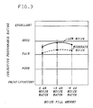
- the noise fill signal to be provided during gaps in the output speech signal at output 31 of receiver 20 to provide improved subjective performance of speech signals was found to occur when the noise signal reduced below the 0 dB noise match value. More particularly, in an illustrative example shown in FIG. 3, the subjective performance of speech transmission is found to be improved, in accordance with the concept of the present invention, as the noise fill signal is reduced below the 0 dB noise match value. From the graph of FIG. 3, it can be seen that the subjective performance was found to increasingly improve as the background noise fill is decreased from the 0 dB noise match value until it reaches a maximum between the -3 and -6 dB noise match value depending on the actual noise level at input 11.
- the subjective performance was found to decrease at noise match values below -3 dB. Therefore, it is shown that the end users find the subjective performance of speech transmission better when the noise match level is reduced below the 0 dB, level with the best subjective performance occurring between the -3 and -6 dB noise match levels.
Abstract
Description
- The present invention relates to a technique for providing improved subjective performance in a communication system or network. More particularly, during moments when no speech or other information signal is being transmitted to an end user during a call, a noise-fill level is provided to a connected end user which is at a predetermined level below that normally found on a channel when there is both an information signal and a noise signal being received.
- In certain communication systems it has been found advantageous to insert noise when a speech or data signal is not present. More particularly, in, for example, a packet communication system, an access interface (AI) generates voice packets only when its speech detector determines that there is activity present on a trunk. When gaps are encountered in the packet stream, the receiving AI inserts noise at a level corresponding to the continuous read-time estimates of the background noise present in the incoming trunk. These estimates can, for example, be made at the transmitting AI and sent to the receiving AI in the packet headers or preambles. Noise insertion is performed to prevent degradations in voice quality that could result from obvious discontinuities in the background noise level as the speech transmission is switched on and off. The term "noise pumping" is frequently used to describe the sudden changes in noise associated with inadequate background noise matching.
- An exemplary communication system that uses a noise-matching technique is described, for example, in (1) the article "TASI-E Communication System" by R. L. Easton et al in IEEE Transactions On Communications, Vol. COM-30, No. 4, April1982, at pages 803-807, and in particular at pages 804 and 805, and (2) in U. S. patent 4,408,324 issued to D. H. A. Black et al. on October 4, 1983. In such communication system, a channel-checking arrangement is used to periodically measure, inter alia, the noise on the channels of the system, the measured channel noise then being used along with the measured background noise on the incoming trunk in a noise-matching operation during silent periods on the channel. In other words, when a trunk is not connected to a channel, such communication system inserts noise at the transmitting or receiving end of the channel to make the total noise at the channel output equal to the same value as when the trunk is connected to the channel and a signal is being transmitted over the channel, thereby avoiding various effects such as noise-pumping.
- Similar techniques are also used in digital conferencing arrangements as described, for example, in U.S. patent 4,482,998 issued to M. A. Marouf et al. on November 13, 1984. There, when no one is momentarily speaking during a conference connection, which is formed from a plurality of ports on a bridge connection, a minimum number of selected ports are maintained in a holdover state to provide background noise on the bridge. This ensures that each conferee receives some minimum background noise to eliminate the feeling that the conferee is cut off from the conference.
- The problem remaining in the prior art is to provide a technique which can further improve, if possible, the subjective performance of a communication system, which includes speech interpolation and may or may not include noise-matching.
- The foregoing problem in the prior art has been solved in accordance with the present invention which relates to a technique in a communication system such as, for example, a Wideband Packet Technology (WPT) Access Interface (AI) with speech interpolation, wherein a noise measurement at the transmitter end, or the reproduced noise-fill at the receiver end, is attenuated or reduced by a predetermined amount from the average monitored level of noise normally received over a channel when communication is taking place before being provided to an end user during non-information transmission periods.
-
- FIG. 1 is a block diagram of pertinent parts of an exemplary communication system employing the reduced noise-fill technique of the present invention:
- FIG. 2 depicts an exemplary arrangement for a combination of a speech detector, noise measuring means and a attenuator in the transmitter of FIG.1; and
- FIG. 3 is a graph representing exemplary result of providing improved subjective performance of speech transmission by reducing the amount of noise fill provided during gaps in the speech transmission below the point (O dB) where the matched noise level is exactly equal to the input noise level.
- FIG. 1 shows only pertinent parts of a
transmitter 10 and areceiver 20 within a communication system for practicing the present noise-matching technique, where information signal detection and noise measurements are performed attransmitter 10 and used at both thetransmitter 10 and theassociated receiver 20. For purposes of explanation hereinafter, it will be assumed that the information signal used as an input totransmitter 10 is a speech signal, but it should be understood that the information signal could comprise any other information signal, such as a music signal, that a person associated with a remote receiver might be listening to. Additionally, it should be understood that any form of information signal transmission can be used for practicing the present invention of noise matching, as, for example, analog, digital or packet transmission with a wideband or narrow band spectrum, since the form of transmission is arbitrary. - More particularly, during a connection between two end users in voice communication, the input speech signal from a first end user at
input 11 is directed to each of (a) afirst input terminal 13 of a switching means 12,(b) aspeech detector 16, and (c) anoise measuring arrangement 17. Another input signal, such as data signals, that might be sent over thesame communication channel 18 betweentransmitter 10 andreceiver 20 is provided as an input to a second input terminal 14 of switching means 12.Speech detector 16monitors input 11 to determine whether a speech signal is active (present) or inactive (not present) and provides an output control signal which is representative of the speech activity and is received by both switching means 12 intransmitter 10 andremote receiver 20 viacommunication channel 18. The control signal fromspeech detector 16 causes switching means 12 intransmitter 10 to (a) connectinput terminal 13 tooutput terminal 15 when a speech signal is being detected atinput 11 in order to transmit the detected speech signal toreceiver 20 overcommunication channel 18, and (b) to connect input terminal 14 tooutput terminal 15 when a speech signal atinput 11 is not detected in order to transmit the other input signal, when present, arriving at second input terminal 14 of switching means 12 toreceiver 20 overcommunication channel 18. The other input signal on input 14 of switching means 12 can be, for example, a packet signal which has its packets stored in a memory (not shown) for transmission by a gating means (not shown) which is responsive to the same speech detector output control signal that causes switching means 12 to connect its input 14 with itsoutput 15. In this manner other signals can be transmitted oncommunication channel 18 when it is not being used for the speech signal transmission and thereby provide a Speech Interpolation technique. -
Noise measuring arrangement 17 is used to determine the level of the background noise in the speech signal atinput 11 and to generate a background noise level control signal for transmission either directly toreceiver 20 overcommunication channel 18 or indirectly toreceiver 20 viaoptional attenuator arrangement 19. In accordance with the present invention, whenattenuator arrangement 19 is present intransmitter 10, it functions to reduce the value of the determined background noise level by a predetermined amount before being transmitted toreceiver 20 overchannel 18. It is to be understood thatattenuator arrangement 19 is an optional element and (a) is, therefore, shown by dashed lines, and (b) when present intransmitter 10 can form a part ofnoise measuring arrangement 17. Alternatively,attenuator arrangement 19 can be disposed inreceiver 20 as anoptional attenuator arrangement 22 as will be described hereinafter. It is to be understood that the concurrent information, active/inactive, and noise value signals transmitted oncommunication channel 18 are transmitted as separate portions of an overall communication signal and, therefore, can be concurrently transmitted in any suitable manner such as, for example, on separate leads or in a composite signal in, for example, the header and information portions of a packet or in different frequency subbands of the composite signal. It is to be understood thatspeech detector 16 andnoise measuring arrangement 17 may actually be formed as part of one circuit as will be shown hereinafter in FIG. 2, but is described here as separate elements for ease of description. - At
receiver 20, (a) the active/inactive control signal portion is received by each of a first and a second switching means 23 and 27 in order to control the path through these switching means; (b) the information signal portion is received at aninput terminal 28 of second switching means 27; and (c) the noise value control signal portion is received by anoise generator 21.Noise generator 21 is responsive to the background noise level control signal transmitted bynoise measuring arrangement 17 intransmitter 10 for generating a level of noise which corresponds to the level of background noise indicated by the received background noise level control signal. In accordance with the present invention, the background noise signal produced bynoise generator 21 is provided to theinput terminal 24 of first switching means 23 either (a) directly when the noise value signal fromnoise measuring arrangement 17 has been previously attenuated by the predetermined amount inattenuator 19, or (b) indirectly viaattenuator 22 when the noise value signal fromnoise measuring arrangement 17 has not been previously attenuated before being transmitted. It is to be understood thatoptional attenuator 22 can be a separate circuit, disposed before or afternoise generator 21, or form a part ofnoise generator 21. Regardless of whichattenuator input terminal 24 of first switching means 24 is a signal which has been attenuated or reduced in level by a predetermined amount from the background noise level which was determined for the signal atinput 11 oftransmitter 10. - In operation, when
speech detector 16 attransmitter 10 detects the presence of a speech signal, including background noise, atinput 11, it generates a control signal having first value which is transmitted toreceiver 20 while simultaneously causing switching means 12 to connectinput terminal 13 tooutput terminal 15 and thereby transmit the speech signal, and included background noise, toreceiver 20.Noise measuring arrangement 17, which has been continuously determining the background noise level received atinput 11, transmits a noise value, which either has been attenuated (whenattenuator 19 is present) or has not been attenuated (whenattenuator 19 is not present) toreceiver 20. Atreceiver 20, the received first value control signal fromspeech detector 16 causes first switching means 23 to close the path betweeninput terminal 24 andoutput terminal 25 to divert any noise signal fromnoise generator 21 away from afirst output path 31 ofreceiver 20, while simultaneously causing second switching means 27 to close the path betweeninput terminal 28 andoutput terminal 30 to direct the received speech signal, and included background noise, tofirst output path 31. - When
speech detector 16 does not detect a speech signal atinput 11 oftransmitter 10, it generates a control signal having a second value which is transmitted toreceiver 20 overcommunication channel 18 while simultaneously causing switching means 12 to connect input terminal 14 tooutput terminal 15 and thereby transmit other input signals toreceiver 20. Atreceiver 20,Noise Generator 21 generates a noise signal at a level specified by the current measured background noise level of the signal atinput 11, or by a prior measured background noise level value measured during a last period when speech signal was not detected, this noise level being determined intransmitter 10 bynoise measuring arrangement 17 with or withoutoptional attenuator 19. The received second value control signal fromspeech detector 16 causes first switching means 23 to close the path betweeninput terminal 24 andoutput terminal 26 to direct the attenuated noise fill signal obtained fromnoise generator 21 and optional attenuator 22 (when present) ontofirst output path 31 fromreceiver 20, while simultaneously causing second switching means 27 to close the path betweeninput terminal 28 andoutput terminal 29 to direct the received other information signals onto asecond output path 32 fromreceiver 20. - By the above technique, when a speech signal, including background noise, is detected at
input 11 oftransmitter 10, the speech plus background noise signal is transmitted toreceiver 20 via switching means 12 andcommunication channel 18, and directed ontofirst output path 31 fromreceiver 20 by second switching means 28. No additional attenuated noise fill signal is provided tofirst output path 31 from first switching means 23 because the path betweeninput terminal 24 andoutput terminal 26 is not closed. When no speech signal is detected atinput 11 oftransmitter 10, then another input signal is transmitted via switching means 12 andcommunication channel 18 toreceiver 20 in place of the normally transmitted speech signal, where this other information signal is directed by second switching means 27 ontosecond output path 32 while only an attenuated noise fill signal is transmitted overfirst output path 31 to the listening, or possibly speaking, end user. It is to be understood that first and second switching means 23 and 27 atreceiver 20 can have any suitable arrangement to realize comparable interconnections. - In an exemplary wideband
packet technology transmitter 10, which is also known as an access interface (AI), with digital speech interpolation, an exemplary arrangement for providing noise matching intransmitter 10 according to the present invention is shown in FIG. 2. In the arrangement of FIG. 2, it will be seen thatspeech detector 16,noise measuring arrangement 17 andoptional attenuator 19 of FIG. 1 can all be formed as part ofspeech detector 16. Noise matching involves two functions, noise level estimation and noise generation. Noise level estimation is performed as part of the speech detection function inspeech detector 16 by the following exemplary digital circuits. The speech signal atinput 11 is high-pass filtered in HPfilter 40 to reduce hum and remove any DC component. The resultant signal is full-wave rectified inrectifier 41 and then low-pass filtered inLP filter 42. The resulting envelope signal is monitored inpeak monitor circuit 43 for the peaks and minima levels. These peak and minima levels are taken to be measures of the speech level and the background noise level, respectively, and are used byspeech detector 16 in setting its speech threshold. In accordance with the present invention, when the noise value to be transmitted toreceiver 20 is to be attenuated before transmission toreceiver 20,optional attenuator 19 would be used with anoise level translator 44 to provide a digital noise value which is at the predetermined reduced or attenuated value. It is to be understood thatattenuator 19 can be either before or after or a part ofnoise level translator 44. - In operation, the noise level measure from
speech detector 16 can be made available as, for example, an 8-bit quantity for transmission tonoise level translator 44 and/orattenuator 19. The range of noise levels this represents could be divided into 16 exemplary parts and translated to a 4-bit noise level value bynoise level translator 44. This 4-bit noise level value would be transmitted in, for example, the header of each speech packet during the period when the end user associated withinput 11 is active and providing a speech signal. When the end user associated withinput 11 becomes inactive and, therefore, packets are no longer sent, the noise level value transmitted in the last packet, and received atreceiver 20, is used to generate an appropriate random noise signal bynoise generator 21, which noise signal is inserted in the speech gap atoutput 31 by switchingmeans 23. In an exemplary arrangement ofnoise generator 21, for each of the 16 noise levels,noise generator 21 can produce a random or pseudorandom sequence of Pulse Code Multiplex (PCM) samples with the desired noise powers. - In accordance with the present invention, the noise fill signal to be provided during gaps in the output speech signal at
output 31 ofreceiver 20 to provide improved subjective performance of speech signals was found to occur when the noise signal reduced below the 0 dB noise match value. More particularly, in an illustrative example shown in FIG. 3, the subjective performance of speech transmission is found to be improved, in accordance with the concept of the present invention, as the noise fill signal is reduced below the 0 dB noise match value. From the graph of FIG. 3, it can be seen that the subjective performance was found to increasingly improve as the background noise fill is decreased from the 0 dB noise match value until it reaches a maximum between the -3 and -6 dB noise match value depending on the actual noise level atinput 11. The subjective performance was found to decrease at noise match values below -3 dB. Therefore, it is shown that the end users find the subjective performance of speech transmission better when the noise match level is reduced below the 0 dB, level with the best subjective performance occurring between the -3 and -6 dB noise match levels.
Claims (7)
CHARACTERIZED IN THAT
the receiver comprises:
means for receiving from a remote transmitter first active signal transmissions interspersed with second inactive signal transmissions which are destined for a predetermined end user of the receiver; and
generating and directing means responsive to (a) a first control signal indicating each period of first active signal transmission for directing the received first active signal transmission to the predetermined end user, and (2) both a second control signal indicating each period of second inactive signal transmission, and a third control signal indicating a background noise level measured at the input of the remote transmitter for generating a noise fill signal comprising a level that is attenuated by a predetermined amount from the background noise level measured at the input of the remote transmitter and directing the attenuated noise fill signal to the predetermined end user during each second inactive signal transmission period for providing improved subjective performance.
CHARACTERIZED IN THAT
the generating and directing means generates and directs a noise fill signal to the predetermined end user which is at a level between -1dB and -6 dB of the background noise level measured at the input of the remote transmitter.
CHARACTERIZED IN THAT
the generating and directing means comprises:
switching means responsive to the second control signal for (1) directing a second different first active signal transmission destined for a predetermined second end user of the receiver which is received from the remote transmitter over a same channel to the predetermined second end user, while concurrently (2) directing the attenuated noise fill signal to the predetermined first end user.
Applications Claiming Priority (2)
| Application Number | Priority Date | Filing Date | Title |
|---|---|---|---|
| US07/209,458 US4864561A (en) | 1988-06-20 | 1988-06-20 | Technique for improved subjective performance in a communication system using attenuated noise-fill |
| US209458 | 1988-06-20 |
Publications (2)
| Publication Number | Publication Date |
|---|---|
| EP0348078A2 true EP0348078A2 (en) | 1989-12-27 |
| EP0348078A3 EP0348078A3 (en) | 1992-03-11 |
Family
ID=22778830
Family Applications (1)
| Application Number | Title | Priority Date | Filing Date |
|---|---|---|---|
| EP19890305849 Withdrawn EP0348078A3 (en) | 1988-06-20 | 1989-06-09 | Technique for improved subjective perfomance in a communication system using attenuated noise-fill |
Country Status (7)
| Country | Link |
|---|---|
| US (1) | US4864561A (en) |
| EP (1) | EP0348078A3 (en) |
| JP (1) | JPH0239744A (en) |
| KR (1) | KR920007478B1 (en) |
| CN (1) | CN1038730A (en) |
| AU (1) | AU596333B2 (en) |
| CA (1) | CA1332453C (en) |
Cited By (2)
| Publication number | Priority date | Publication date | Assignee | Title |
|---|---|---|---|---|
| WO1999013664A1 (en) * | 1997-09-12 | 1999-03-18 | Telefonaktiebolaget Lm Ericsson (Publ) | Method and arrangement for splitting signalling and speech in an analog mobile telephone system |
| EP1017042A1 (en) * | 1994-01-28 | 2000-07-05 | AT&T Corp. | Voice activity detection driven noise remediator |
Families Citing this family (23)
| Publication number | Priority date | Publication date | Assignee | Title |
|---|---|---|---|---|
| US5095540A (en) * | 1990-02-28 | 1992-03-10 | Motorola, Inc. | Hole placement and fill system based on category selection |
| GB9006088D0 (en) * | 1990-03-17 | 1990-05-16 | Digital Equipment Int | Interference suppression |
| US5065395A (en) * | 1990-04-09 | 1991-11-12 | Dsc Communications Corporation | Rudimentary digital speech interpolation apparatus and method |
| ES2240252T3 (en) * | 1991-06-11 | 2005-10-16 | Qualcomm Incorporated | VARIABLE SPEED VOCODIFIER. |
| DE4305961A1 (en) * | 1993-02-26 | 1994-09-01 | Nokia Deutschland Gmbh | Arrangement for generating a noise detector signal |
| US5559832A (en) * | 1993-06-28 | 1996-09-24 | Motorola, Inc. | Method and apparatus for maintaining convergence within an ADPCM communication system during discontinuous transmission |
| TW271524B (en) | 1994-08-05 | 1996-03-01 | Qualcomm Inc | |
| US5742734A (en) * | 1994-08-10 | 1998-04-21 | Qualcomm Incorporated | Encoding rate selection in a variable rate vocoder |
| GB2294614B (en) * | 1994-10-28 | 1999-07-14 | Int Maritime Satellite Organiz | Communication method and apparatus |
| US5740542A (en) * | 1995-08-02 | 1998-04-14 | Motorola, Inc. | Method of transmitting data during voice pauses in a synchronous communication system |
| US5625687A (en) * | 1995-08-31 | 1997-04-29 | Lucent Technologies Inc. | Arrangement for enhancing the processing of speech signals in digital speech interpolation equipment |
| US5615214A (en) * | 1995-10-30 | 1997-03-25 | Motorola, Inc. | System and method of compensating propagation time variations and substituting for lost packets in a packetized voice communication system |
| US5751901A (en) * | 1996-07-31 | 1998-05-12 | Qualcomm Incorporated | Method for searching an excitation codebook in a code excited linear prediction (CELP) coder |
| US5881373A (en) * | 1996-08-28 | 1999-03-09 | Telefonaktiebolaget Lm Ericsson | Muting a microphone in radiocommunication systems |
| US6295302B1 (en) | 1998-04-24 | 2001-09-25 | Telefonaktiebolaget L M Ericsson (Publ) | Alternating speech and data transmission in digital communications systems |
| US6438131B1 (en) * | 1998-07-28 | 2002-08-20 | Lucent Technologies Inc. | Low-overhead service specific convergence layer for voice and telephony over packet-based systems |
| US6691084B2 (en) | 1998-12-21 | 2004-02-10 | Qualcomm Incorporated | Multiple mode variable rate speech coding |
| DE69933929T2 (en) * | 1999-04-09 | 2007-06-06 | Texas Instruments Inc., Dallas | Providing digital audio and video products |
| US7263074B2 (en) * | 1999-12-09 | 2007-08-28 | Broadcom Corporation | Voice activity detection based on far-end and near-end statistics |
| US6873604B1 (en) * | 2000-07-31 | 2005-03-29 | Cisco Technology, Inc. | Method and apparatus for transitioning comfort noise in an IP-based telephony system |
| US8457614B2 (en) * | 2005-04-07 | 2013-06-04 | Clearone Communications, Inc. | Wireless multi-unit conference phone |
| US20070248813A1 (en) * | 2006-04-25 | 2007-10-25 | Xerox Corporation | Imaging member having styrene |
| RU2651803C1 (en) * | 2016-12-22 | 2018-04-24 | Акционерное общество "Научно-производственное предприятие "Полет" | Noise suppressor |
Citations (3)
| Publication number | Priority date | Publication date | Assignee | Title |
|---|---|---|---|---|
| US4408324A (en) * | 1980-10-03 | 1983-10-04 | Black David H A | Noise signal level control in a TASI system |
| JPS59182644A (en) * | 1983-03-31 | 1984-10-17 | Mitsubishi Electric Corp | Noise signal generating circuit of digital sound inserting device |
| JPS59182645A (en) * | 1983-03-31 | 1984-10-17 | Mitsubishi Electric Corp | Noise signal generating circuit of digital sound inserting device |
Family Cites Families (6)
| Publication number | Priority date | Publication date | Assignee | Title |
|---|---|---|---|---|
| US4059730A (en) * | 1976-08-17 | 1977-11-22 | Bell Telephone Laboratories, Incorporated | Apparatus for mitigating signal distortion and noise signal contrast in a communications system |
| JPS6051820B2 (en) * | 1977-03-04 | 1985-11-15 | 日本電気株式会社 | Digital audio input method |
| US4482998A (en) * | 1982-05-27 | 1984-11-13 | At&T Bell Laboratories | Method and apparatus for improving the quality of communication in a digital conference arrangement |
| GB2132452B (en) * | 1982-12-08 | 1986-10-08 | Racel Ses Limited | Radio systems |
| US4648118A (en) * | 1984-04-20 | 1987-03-03 | Matsushita Electric Industrial Co., Ltd. | Apparatus for reducing noise in audio signals |
| US4630304A (en) * | 1985-07-01 | 1986-12-16 | Motorola, Inc. | Automatic background noise estimator for a noise suppression system |
-
1988
- 1988-06-20 US US07/209,458 patent/US4864561A/en not_active Expired - Lifetime
-
1989
- 1989-05-08 CA CA000598961A patent/CA1332453C/en not_active Expired - Fee Related
- 1989-05-31 JP JP1139008A patent/JPH0239744A/en active Pending
- 1989-06-01 AU AU35969/89A patent/AU596333B2/en not_active Ceased
- 1989-06-09 EP EP19890305849 patent/EP0348078A3/en not_active Withdrawn
- 1989-06-16 CN CN89104045A patent/CN1038730A/en active Pending
- 1989-06-17 KR KR1019890008361A patent/KR920007478B1/en not_active IP Right Cessation
Patent Citations (3)
| Publication number | Priority date | Publication date | Assignee | Title |
|---|---|---|---|---|
| US4408324A (en) * | 1980-10-03 | 1983-10-04 | Black David H A | Noise signal level control in a TASI system |
| JPS59182644A (en) * | 1983-03-31 | 1984-10-17 | Mitsubishi Electric Corp | Noise signal generating circuit of digital sound inserting device |
| JPS59182645A (en) * | 1983-03-31 | 1984-10-17 | Mitsubishi Electric Corp | Noise signal generating circuit of digital sound inserting device |
Non-Patent Citations (4)
| Title |
|---|
| NTC 1978 VOL. 1, 3 December 1978, BIRMINGHAM, US PAGES 14.2.1 - 14.2.5 J.A. SCIULLI : " SYSTEM ENGINEERING CONSIDERATIONS IN DSI APPLICATIONS " * |
| NTC 1978 VOL. 1, 3 December 1978, BIRMINGHAM, US PAGES 14.5.1 - 14.5.5 D. LOMBARD et al. : " CELTIC FIELD TRIAL RESULTS" * |
| PATENT ABSTRACTS OF JAPAN vol. 9, no. 43 (E-298)(1766) 22 February 1985 & JP-A-59 182 644 ( MITSUBISHI ) * |
| PATENT ABSTRACTS OF JAPAN vol. 9, no. 43 (E-298)(1766) 22 February 1985 & JP-A-59 182 645 ( MITSUBISHI ) * |
Cited By (4)
| Publication number | Priority date | Publication date | Assignee | Title |
|---|---|---|---|---|
| EP1017042A1 (en) * | 1994-01-28 | 2000-07-05 | AT&T Corp. | Voice activity detection driven noise remediator |
| WO1999013664A1 (en) * | 1997-09-12 | 1999-03-18 | Telefonaktiebolaget Lm Ericsson (Publ) | Method and arrangement for splitting signalling and speech in an analog mobile telephone system |
| US6097946A (en) * | 1997-09-12 | 2000-08-01 | Telefonaktiebolaget Lm Ericsson | Method and arrangement for mobile telephony |
| ES2199621A1 (en) * | 1997-09-12 | 2004-02-16 | Ericsson Telefon Ab L M | Method and arrangement for splitting signalling and speech in an analog mobile telephone system |
Also Published As
| Publication number | Publication date |
|---|---|
| AU596333B2 (en) | 1990-04-26 |
| CN1038730A (en) | 1990-01-10 |
| KR920007478B1 (en) | 1992-09-04 |
| AU3596989A (en) | 1989-12-21 |
| KR910002146A (en) | 1991-01-31 |
| EP0348078A3 (en) | 1992-03-11 |
| JPH0239744A (en) | 1990-02-08 |
| US4864561A (en) | 1989-09-05 |
| CA1332453C (en) | 1994-10-11 |
Similar Documents
| Publication | Publication Date | Title |
|---|---|---|
| US4864561A (en) | Technique for improved subjective performance in a communication system using attenuated noise-fill | |
| CA1254278A (en) | Method and apparatus for improved control and time sharing of an echo canceller | |
| EP0376582B1 (en) | Computer controlled adaptive speakerphone | |
| US6775240B1 (en) | System and methods for measuring quality of communications over packet networks | |
| EP0791251B1 (en) | Echo cancellation using cross-correlation of buffered receive and transmit sample segments to determine cancelling filter coefficients | |
| EP0717913B1 (en) | Data transmission method, base station, and subscriber terminal | |
| US4571461A (en) | Conference telephone apparatus | |
| JP2512418B2 (en) | Voice conditioning device | |
| GB2136253A (en) | Echo envelope generator | |
| CA1236906A (en) | Conference circuits and methods of operating them | |
| CA2055364C (en) | Enhanced acoustic calibration procedure for a voice switched speakerphone | |
| US6078882A (en) | Method and apparatus for extracting speech spurts from voice and reproducing voice from extracted speech spurts | |
| US6771701B1 (en) | Adaptive filter divergence control in echo cancelers by means of amplitude distribution evaluation with configurable hysteresis | |
| US4382164A (en) | Signal stretcher for envelope generator | |
| US6535844B1 (en) | Method of detecting silence in a packetized voice stream | |
| GB2072466A (en) | Time assigned speech interpolation system | |
| US3985979A (en) | Half-echo suppressor for a terminal of a four-wire electric line | |
| US5982755A (en) | System and method for providing high terminal coupling loss in a handsfree terminal | |
| Nakhla et al. | Analysis of a TASI system employing speech storage | |
| US20030198193A1 (en) | Speaker tracking on a single core in a packed based conferencing system | |
| EP0194785A2 (en) | Packet switching system | |
| US6307870B1 (en) | Process for transmitting digitized payload and signalling data over a channel | |
| US6438224B1 (en) | Tone detection | |
| JP3231699B2 (en) | Voice detector, voice detection method, and high-efficiency terminal device | |
| JP3251935B2 (en) | Data modem receiver |
Legal Events
| Date | Code | Title | Description |
|---|---|---|---|
| PUAI | Public reference made under article 153(3) epc to a published international application that has entered the european phase |
Free format text: ORIGINAL CODE: 0009012 |
|
| 17P | Request for examination filed |
Effective date: 19890623 |
|
| AK | Designated contracting states |
Kind code of ref document: A2 Designated state(s): DE ES FR GB IT NL SE |
|
| PUAL | Search report despatched |
Free format text: ORIGINAL CODE: 0009013 |
|
| AK | Designated contracting states |
Kind code of ref document: A3 Designated state(s): DE ES FR GB IT NL SE |
|
| 17Q | First examination report despatched |
Effective date: 19931126 |
|
| RAP3 | Party data changed (applicant data changed or rights of an application transferred) |
Owner name: AT&T CORP. |
|
| STAA | Information on the status of an ep patent application or granted ep patent |
Free format text: STATUS: THE APPLICATION HAS BEEN WITHDRAWN |
|
| 18W | Application withdrawn |
Withdrawal date: 19950315 |