EP0348011A2 - Ceiling mounted air cleaner - Google Patents
Ceiling mounted air cleaner Download PDFInfo
- Publication number
- EP0348011A2 EP0348011A2 EP89201653A EP89201653A EP0348011A2 EP 0348011 A2 EP0348011 A2 EP 0348011A2 EP 89201653 A EP89201653 A EP 89201653A EP 89201653 A EP89201653 A EP 89201653A EP 0348011 A2 EP0348011 A2 EP 0348011A2
- Authority
- EP
- European Patent Office
- Prior art keywords
- air
- air cleaner
- fan
- outer shell
- shell
- Prior art date
- Legal status (The legal status is an assumption and is not a legal conclusion. Google has not performed a legal analysis and makes no representation as to the accuracy of the status listed.)
- Withdrawn
Links
Images



Classifications
-
- F—MECHANICAL ENGINEERING; LIGHTING; HEATING; WEAPONS; BLASTING
- F24—HEATING; RANGES; VENTILATING
- F24F—AIR-CONDITIONING; AIR-HUMIDIFICATION; VENTILATION; USE OF AIR CURRENTS FOR SCREENING
- F24F13/00—Details common to, or for air-conditioning, air-humidification, ventilation or use of air currents for screening
- F24F13/28—Arrangement or mounting of filters
-
- F—MECHANICAL ENGINEERING; LIGHTING; HEATING; WEAPONS; BLASTING
- F24—HEATING; RANGES; VENTILATING
- F24F—AIR-CONDITIONING; AIR-HUMIDIFICATION; VENTILATION; USE OF AIR CURRENTS FOR SCREENING
- F24F8/00—Treatment, e.g. purification, of air supplied to human living or working spaces otherwise than by heating, cooling, humidifying or drying
- F24F8/10—Treatment, e.g. purification, of air supplied to human living or working spaces otherwise than by heating, cooling, humidifying or drying by separation, e.g. by filtering
- F24F8/108—Treatment, e.g. purification, of air supplied to human living or working spaces otherwise than by heating, cooling, humidifying or drying by separation, e.g. by filtering using dry filter elements
-
- F—MECHANICAL ENGINEERING; LIGHTING; HEATING; WEAPONS; BLASTING
- F24—HEATING; RANGES; VENTILATING
- F24F—AIR-CONDITIONING; AIR-HUMIDIFICATION; VENTILATION; USE OF AIR CURRENTS FOR SCREENING
- F24F8/00—Treatment, e.g. purification, of air supplied to human living or working spaces otherwise than by heating, cooling, humidifying or drying
- F24F8/10—Treatment, e.g. purification, of air supplied to human living or working spaces otherwise than by heating, cooling, humidifying or drying by separation, e.g. by filtering
-
- F—MECHANICAL ENGINEERING; LIGHTING; HEATING; WEAPONS; BLASTING
- F24—HEATING; RANGES; VENTILATING
- F24F—AIR-CONDITIONING; AIR-HUMIDIFICATION; VENTILATION; USE OF AIR CURRENTS FOR SCREENING
- F24F2221/00—Details or features not otherwise provided for
- F24F2221/14—Details or features not otherwise provided for mounted on the ceiling
Definitions
- the present invention relates to ceiling mounted air cleaners and in particular to a novel ceiling mounted air cleaner of modular construction which is easily installed by an unassisted individual.
- Ceiling mounted air cleaners are known and currently available as either flush mounted or surface mounted units.
- the surface mounted units generally comprise box-shaped structures having an air intake on the surface remote from the ceiling and a plurality of air exhaust ports on the sides of the unit. They are mounted directly on the ceiling surface and most currently available models are relatively large and bulky.
- the flush mounted units are generally used for suspended ceiling installations, the unit being mounted to the surface which supports the ceiling so that the bottom surface of the unit either arrives flush with the suspended ceiling or projects slightly beyond it. Both the intake and exhaust ports in the known flush mounted air cleaners are located in the bottom surface of the unit.
- the ceiling mounted air cleaner in accordance with the invention is of light weight, modular construction permitting it to be disassembled and installed by an unassisted person.
- a ceiling mounted air cleaner in accordance with the invention may be installed as either a flush mounted or a surface mounted unit, optional decorative panels being provided to match the decor of the environment if the unit is surface mounted.
- the present invention comprises a ceiling mountable air cleaner comprising: an outer shell having top and side surfaces; an inner shell having top and side surfaces, the top surface being provided with an opening having a shroud which projects inwardly from said surface; spacer means to retain the top surfaces of said outer shell and inner shell in a parallel, spaced apart relationship; air outlet means communicating with said space between said outer and inner shells; a fan subassembly located within said inner shell, said subassembly comprising a fan having a plurality of fan blades radiating from a central hub and located within said shroud, means for turning said fan blades and means for supporting said fan; an air filter subassembly comprising an air filter and means for supporting said air filter while providing for the inlet of air, said subassembly being attached to the open side of one of said inner shell or said outer shell; and a skeleton frame for supporting said outer shell, said inner shell and said fan subassembly in the aforesaid relationships.
- a ceiling mounted air cleaner in accordance with the invention is generally referred to by the reference 1.
- Optional decorative panels 2 are provided for surface mounted applications.
- a grill or screen 3 covers the air intake opening in the air filter unit.
- Louvres 4 provided on each lower edge of the unit provide the air outlet passages for the air cleaner.
- Fig. 2 illustrates the air cleaner 1 surface mounted on a ceiling.
- the decorative panels 2 are installed to provide an aesthetically pleasing appearance.
- Decorative panels 2 are optionally provided in a variety of colours and textures to match the decor of the environment. They are attached to the sides of outer shell 5 with an adhesive such as velcro strips (not illustrated) or sliding engagement fasteners (not illustrated).
- Fig. 3 illustrates the air cleaner 1 flush mounted in a suspended ceiling. When flush mounted, only the air outlet louvres 4 and the air intake grill 3 are exposed below the ceiling surface.
- the housing of the air cleaner 1 comprises an outer shell generally referred to by the reference 5, a supporting skeleton frame generally referred to by the reference 7, and an inner shell generally referred to by the reference 15.
- the outer shell 5 comprises a box-shaped structure closed on its top and sides and open on its lower surface.
- a short lip 5a projects outwardly along the bottom edges of outer shell 5.
- the projecting lip 5a contacts the upper edges of louvres 4 as will be explained hereinafter.
- the outer shell 5 is preferably constructed of light weight sheet metal or a durable molded plastic.
- the sturdy skeleton frame 7 is preferably constructed of aluminum or steel and supports all of the components of the air cleaner.
- the inner shell 15 comprises a box structure provided with a circular opening in the center of its top surface which is surrounded by an inwardly projecting shroud 17. The bottom edges of the inner shell 15 are turned outwards and upwards to provide the louvres 4 which act as the outlets for air cleaned by the unit.
- the inner shell 15 is likewise preferably constructed of light weight sheet metal or molded plastic.
- the air cleaner further comprises fan blades 18 which are powered by an electric motor 19.
- Electric motor 19 is attached to a support plate 21 with threaded nuts 23.
- the connection of support plate 21 to the skeleton frame 7 will be explained hereinafter in detail.
- An air filter 26 rests in an air filter frame 27 which is provided with a grill or screen 3 as previously described.
- Fig. 5 illustrates a cross-section of the assembled air cleaner in the configuration for flush mounting in a ceiling as illustrated in Fig. 3.
- a pad of sound insulating material 29, of open celled plastic foam, or the like, is permanently attached to the upper inside surface of outer shell 5.
- the pad 29 helps to absorb sound generated by fan blades 18 as will be explained below in greater detail.
- the outer shell 5 (see Fig. 4a) is provided with four holes 6 positioned in each corner region of its upper surface.
- the skeleton frame 7 is provided with four complementary holes 12. Screw fasteners or lag bolts (not illustrated) are driven through holes 12 and complementary holes 6 to attach the unit to a ceiling or some adequate support surface above a ceiling.
- Four studs 8, 9, 10 and 11 respectively project downward from skeleton frame 7. Studs 8 and 11 support the inner shell 15 while studs 9 and 10 support the fan bracket 21 (see Fig. 4b).
- outer shell 5 and skeleton frame 7 are simultaneously anchored to a support surface by screw fasteners as described above, spacers 13 are placed on studs 8, 9, 10 and 11 and inner shell 15 is raised into position and secured by a pair of threaded nuts 14 which engage the threaded ends of studs 8 and 11 respectively.
- Spacers 13 retain outer shell 5 and inner shell 15 in a spaced apart relationship to provide a passageway for the output of air cleaned by the unit (see Fig. 5).
- the outturned edges 5a of the outer shell 5 rest atop the upper edges of air outlet louvres 4 of the inner shell 15 when the shells are in their assembled condition (Fig. 5).
- fan motor 19 is attached to fan support bracket 21 by threaded nuts 23.
- Spacers 20 are slipped over studs 9 and 10 respectively (see Fig. 4a) followed by fan support bracket 21 which is secured in place by threaded nuts 25.
- the filter frame 27 is secured to the lower edge of inner shell 15 by a hinge 28.
- the air filter 26 is supported inside the upturned edges of the filter frame 27.
- the filter frame is secured in its closed position by latches or friction fasteners (not illustrated) permitting filter 26 to be changed by unlatching filter frame 27 and rotating the free end of the frame downwards to expose the air filter.
- the ceiling mounted air cleaner 1 operates in the following manner.
- Fan blades 18 are turned by an electric motor 19.
- the longitudinal front edges of fan blades 18 are in close proximity to the sound absorbing planar surface 29.
- Shroud 17 closely surrounds the tips of the fan blades 18.
- the fan blades 18 thereby act as centrifugal impellers, drawing air into the unit through the grill or screen 3 and the filter 26 and ejecting it outwardly and downwardly between the outer sides of the inner shell 15 and the inner sides of the outer shell 5 and through the louvres 4 along the upturned outside edges of the inner shell 15.
- the shroud 17 and the restricted space between inner shell 15 and the outer shell 5 prevent the backflow of cleaned air into the low pressure area created within the inner shell 15 by the action of the fan. Since the backflow of air around the fan blades is practically eliminated, there is a minimum of air turbulence within the air cleaner and the noise generated by air turbulence in the airflow paths of the prior art air cleaner units is practically eliminated, providing an air cleaner of exceptionally quiet and efficient operation.
Landscapes
- Engineering & Computer Science (AREA)
- Chemical & Material Sciences (AREA)
- Combustion & Propulsion (AREA)
- Mechanical Engineering (AREA)
- General Engineering & Computer Science (AREA)
- Filtering Of Dispersed Particles In Gases (AREA)
- Residential Or Office Buildings (AREA)
- Finishing Walls (AREA)
Abstract
A conveniently installed, light weight, modular ceiling mounted air cleaner featuring frame-and-chassis construction which may be flush mounted or surface mounted on a ceiling. Optional decorative panels provide flexibility of decor.
Description
- The present invention relates to ceiling mounted air cleaners and in particular to a novel ceiling mounted air cleaner of modular construction which is easily installed by an unassisted individual.
- Ceiling mounted air cleaners are known and currently available as either flush mounted or surface mounted units. The surface mounted units generally comprise box-shaped structures having an air intake on the surface remote from the ceiling and a plurality of air exhaust ports on the sides of the unit. They are mounted directly on the ceiling surface and most currently available models are relatively large and bulky. The flush mounted units are generally used for suspended ceiling installations, the unit being mounted to the surface which supports the ceiling so that the bottom surface of the unit either arrives flush with the suspended ceiling or projects slightly beyond it. Both the intake and exhaust ports in the known flush mounted air cleaners are located in the bottom surface of the unit.
- Both of the known types of ceiling mounted air cleaners described above have certain disadvantages. In general, they are heavy and require too or more people for their installation. They are expressly manufactured for either flush or surface mounting, requiring suppliers to maintain a stock of both types. In addition, the aerodynamic design of these units is generally poor, resulting in the creation of considerable turbulence within their airflow paths. This turbulence is responsible for the generation of high levels of noise and makes the units undesirable for use in relatively quiet environments. The present invention largely overcomes these disadvantages of the prior art.
- The ceiling mounted air cleaner in accordance with the invention is of light weight, modular construction permitting it to be disassembled and installed by an unassisted person.
- A ceiling mounted air cleaner in accordance with the invention may be installed as either a flush mounted or a surface mounted unit, optional decorative panels being provided to match the decor of the environment if the unit is surface mounted.
- It is an especial advantage of the present invention that the turbulence in the airflow path is reduced, thereby minimizing the noise generated by the unit and making it satisfactory for use in relatively quiet environments.
- In general terms, the present invention comprises a ceiling mountable air cleaner comprising:
an outer shell having top and side surfaces;
an inner shell having top and side surfaces, the top surface being provided with an opening having a shroud which projects inwardly from said surface;
spacer means to retain the top surfaces of said outer shell and inner shell in a parallel, spaced apart relationship;
air outlet means communicating with said space between said outer and inner shells;
a fan subassembly located within said inner shell, said subassembly comprising a fan having a plurality of fan blades radiating from a central hub and located within said shroud, means for turning said fan blades and means for supporting said fan;
an air filter subassembly comprising an air filter and means for supporting said air filter while providing for the inlet of air, said subassembly being attached to the open side of one of said inner shell or said outer shell; and
a skeleton frame for supporting said outer shell, said inner shell and said fan subassembly in the aforesaid relationships. - A preferred embodiment of the invention will now be explained by way of example only and with reference to the following drawings wherein:
- Fig. 1 is a perspective view of an air cleaner in accordance with the invention showing the air cleaner with the decorative panels detached;
- Fig. 2 shows the air cleaner of Fig. 1 surface mounted on a ceiling;
- Fig. 3 illustrates the air cleaner of Fig. 1 flush mounted in a suspended ceiling;
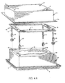
- Fig. 4a illustrates a schematic perspective view of the outside shell, the skeleton frame, and the inside shell of the air cleaner of Fig. 1;
- Fig. 4b illustrates a schematic view of the fan, the air filter and the air filter subassembly of the air cleaner of Fig. 1; and
- Fig. 5 is a schematic cross sectional view of the air cleaner of Fig. 1.
- Referring to the drawings, in Fig. 1 a ceiling mounted air cleaner in accordance with the invention is generally referred to by the reference 1. Optional
decorative panels 2 are provided for surface mounted applications. A grill orscreen 3 covers the air intake opening in the air filter unit. Louvres 4 provided on each lower edge of the unit provide the air outlet passages for the air cleaner. - Fig. 2 illustrates the air cleaner 1 surface mounted on a ceiling. The
decorative panels 2 are installed to provide an aesthetically pleasing appearance.Decorative panels 2 are optionally provided in a variety of colours and textures to match the decor of the environment. They are attached to the sides ofouter shell 5 with an adhesive such as velcro strips (not illustrated) or sliding engagement fasteners (not illustrated). - Fig. 3 illustrates the air cleaner 1 flush mounted in a suspended ceiling. When flush mounted, only the air outlet louvres 4 and the
air intake grill 3 are exposed below the ceiling surface. - Referring now to Fig. 4a, the housing of the air cleaner 1 comprises an outer shell generally referred to by the
reference 5, a supporting skeleton frame generally referred to by thereference 7, and an inner shell generally referred to by thereference 15. Theouter shell 5 comprises a box-shaped structure closed on its top and sides and open on its lower surface. A short lip 5a projects outwardly along the bottom edges ofouter shell 5. The projecting lip 5a contacts the upper edges of louvres 4 as will be explained hereinafter. Theouter shell 5 is preferably constructed of light weight sheet metal or a durable molded plastic. Thesturdy skeleton frame 7 is preferably constructed of aluminum or steel and supports all of the components of the air cleaner. Theinner shell 15 comprises a box structure provided with a circular opening in the center of its top surface which is surrounded by an inwardly projectingshroud 17. The bottom edges of theinner shell 15 are turned outwards and upwards to provide the louvres 4 which act as the outlets for air cleaned by the unit. Theinner shell 15 is likewise preferably constructed of light weight sheet metal or molded plastic. - Referring now to Fig. 4b, the air cleaner further comprises
fan blades 18 which are powered by anelectric motor 19.Electric motor 19 is attached to asupport plate 21 with threadednuts 23. The connection ofsupport plate 21 to theskeleton frame 7 will be explained hereinafter in detail. Anair filter 26 rests in anair filter frame 27 which is provided with a grill orscreen 3 as previously described. - Fig. 5 illustrates a cross-section of the assembled air cleaner in the configuration for flush mounting in a ceiling as illustrated in Fig. 3. A pad of
sound insulating material 29, of open celled plastic foam, or the like, is permanently attached to the upper inside surface ofouter shell 5. Thepad 29 helps to absorb sound generated byfan blades 18 as will be explained below in greater detail. - Referring again to Figs. 4a and 4b, the details of the construction and assembly of the air cleaner 1 will now be described in detail.
- The outer shell 5 (see Fig. 4a) is provided with four
holes 6 positioned in each corner region of its upper surface. Theskeleton frame 7 is provided with fourcomplementary holes 12. Screw fasteners or lag bolts (not illustrated) are driven throughholes 12 andcomplementary holes 6 to attach the unit to a ceiling or some adequate support surface above a ceiling. Fourstuds skeleton frame 7.Studs 8 and 11 support theinner shell 15 whilestuds outer shell 5 andskeleton frame 7 are simultaneously anchored to a support surface by screw fasteners as described above,spacers 13 are placed onstuds inner shell 15 is raised into position and secured by a pair of threaded nuts 14 which engage the threaded ends ofstuds 8 and 11 respectively.Spacers 13 retainouter shell 5 andinner shell 15 in a spaced apart relationship to provide a passageway for the output of air cleaned by the unit (see Fig. 5). The outturned edges 5a of theouter shell 5 rest atop the upper edges of air outlet louvres 4 of theinner shell 15 when the shells are in their assembled condition (Fig. 5). - Referring now to Fig. 4b,
fan motor 19 is attached tofan support bracket 21 by threaded nuts 23.Spacers 20 are slipped overstuds fan support bracket 21 which is secured in place by threaded nuts 25. Thefilter frame 27 is secured to the lower edge ofinner shell 15 by ahinge 28. Theair filter 26 is supported inside the upturned edges of thefilter frame 27. The filter frame is secured in its closed position by latches or friction fasteners (not illustrated) permittingfilter 26 to be changed by unlatchingfilter frame 27 and rotating the free end of the frame downwards to expose the air filter. - Referring again to Fig. 5, the ceiling mounted air cleaner 1 operates in the following manner.
Fan blades 18 are turned by anelectric motor 19. The longitudinal front edges offan blades 18 are in close proximity to the sound absorbingplanar surface 29.Shroud 17 closely surrounds the tips of thefan blades 18. Thefan blades 18 thereby act as centrifugal impellers, drawing air into the unit through the grill orscreen 3 and thefilter 26 and ejecting it outwardly and downwardly between the outer sides of theinner shell 15 and the inner sides of theouter shell 5 and through the louvres 4 along the upturned outside edges of theinner shell 15. Theshroud 17 and the restricted space betweeninner shell 15 and theouter shell 5 prevent the backflow of cleaned air into the low pressure area created within theinner shell 15 by the action of the fan. Since the backflow of air around the fan blades is practically eliminated, there is a minimum of air turbulence within the air cleaner and the noise generated by air turbulence in the airflow paths of the prior art air cleaner units is practically eliminated, providing an air cleaner of exceptionally quiet and efficient operation. - Changes and modifications in the specifically described embodiments can be carried out without departing from the scope of the invention which is intended to be limited only by the scope of the appended claims.
Claims (10)
1. A ceiling mountable air cleaning unit comprising:
an outer shell having top and side surfaces;
an inner shell having top and side surfaces, the top surface being provided with an opening having a shroud which projects inwardly from said surface;
spacer means to retain the top surfaces of said outer shell and inner shell in a parallel, spaced apart relationship;
air outlet means communicating with said space between said outer and inner shells;
a fan subassembly located within said inner shell, said subassembly comprising a fan having a plurality of fan blades radiating from a central hub and located within said shroud, means for turning said fan blades and means for supporting said fan;
an air filter subassembly comprising an air filter and means for supporting said air filter while providing for the inlet of air, said subassembly being attached to the open side of one of said inner shell or said outer shell; and
a skeleton frame for supporting said outer shell, said inner shell and said fan subassembly in the aforesaid relationships.
an outer shell having top and side surfaces;
an inner shell having top and side surfaces, the top surface being provided with an opening having a shroud which projects inwardly from said surface;
spacer means to retain the top surfaces of said outer shell and inner shell in a parallel, spaced apart relationship;
air outlet means communicating with said space between said outer and inner shells;
a fan subassembly located within said inner shell, said subassembly comprising a fan having a plurality of fan blades radiating from a central hub and located within said shroud, means for turning said fan blades and means for supporting said fan;
an air filter subassembly comprising an air filter and means for supporting said air filter while providing for the inlet of air, said subassembly being attached to the open side of one of said inner shell or said outer shell; and
a skeleton frame for supporting said outer shell, said inner shell and said fan subassembly in the aforesaid relationships.
2. An air cleaner as in claim 1 further provided with a pad of sound absorbing material attached to the inside top surface of said outer shell.
3. An air cleaner as in claims 1 or 2 wherein the longitudinal front edges of the blades of said fan are supported in close proximity to the inside top surface of said outer shell.
4. An air cleaner as in claim 1 mounted on a ceiling surface.
5. An air cleaner as in claim 2 mounted on a ceiling surface.
6. An air cleaner as in claims 4 or 5 further provided with decorative panels (2) for covering the exposed sides of said outside shell (5).
7. An air cleaner as in claims 1 or 2 wherein the means (3) for supporting said air filter (26) is provided on its one edge with hinge means (28) to facilitate access to said air filter.
8. The air cleaner as in claim 1 wherein the sides of said outer (5) and inner (15) shells are spaced apart to provide a passage for the outlet of air.
9. The air cleaner as in claim 8 wherein the bottom edges of said inner shell (15) are outturned to contact the bottom edges of said outer shell (5) and provided with air outlet means (4).
10. The air cleaner as in claims 1 or 2 wherein said outer shell (5), said spacer means (13), said inner shell (15) and said fan subassembly are adapted to be assembled in sequence on said skeleton frame (7).
Applications Claiming Priority (2)
| Application Number | Priority Date | Filing Date | Title |
|---|---|---|---|
| CA570191 | 1988-06-23 | ||
| CA570191 | 1988-06-23 |
Publications (2)
| Publication Number | Publication Date |
|---|---|
| EP0348011A2 true EP0348011A2 (en) | 1989-12-27 |
| EP0348011A3 EP0348011A3 (en) | 1991-09-11 |
Family
ID=4138261
Family Applications (1)
| Application Number | Title | Priority Date | Filing Date |
|---|---|---|---|
| EP19890201653 Withdrawn EP0348011A3 (en) | 1988-06-23 | 1989-06-23 | Ceiling mounted air cleaner |
Country Status (3)
| Country | Link |
|---|---|
| EP (1) | EP0348011A3 (en) |
| JP (1) | JPH0299111A (en) |
| AU (1) | AU3700089A (en) |
Cited By (19)
| Publication number | Priority date | Publication date | Assignee | Title |
|---|---|---|---|---|
| DE4018046A1 (en) * | 1990-06-06 | 1991-12-12 | Icleen Entwicklung Vertrieb | VARIABLE AIR FILTER SYSTEM FOR CONVECTION AND VENTILATION AIR FLOWS |
| WO1995001534A1 (en) * | 1993-06-29 | 1995-01-12 | Honeywell Inc. | Air purifying apparatus |
| DE4426572A1 (en) * | 1994-07-27 | 1996-02-01 | Incen Ag | Ventilating closed rooms |
| GB2304888A (en) * | 1995-09-02 | 1997-03-26 | Smiths Industries Plc | Air treatment apparatus |
| WO1999002926A1 (en) * | 1997-06-27 | 1999-01-21 | ABB Fläkt AB | Fan module for clean room applications |
| WO2000022351A1 (en) * | 1998-10-14 | 2000-04-20 | Maendli Erwin | Indoor lamp having an integrated air filter system |
| EP1767873A3 (en) * | 2005-09-22 | 2007-05-02 | LG Electronics, Inc. | Air conditioning apparatus |
| CN1936439B (en) * | 2005-09-22 | 2010-05-12 | Lg电子株式会社 | Air conditioning apparatus |
| DE102009035711A1 (en) * | 2009-07-31 | 2011-02-03 | Kampmann Gmbh | Air conditioning device |
| CN104564743A (en) * | 2015-01-22 | 2015-04-29 | 天津大学 | Air returning type fan filter unit (FFU) below ceiling |
| CN105782085A (en) * | 2016-03-06 | 2016-07-20 | 淄博环能海臣环保技术服务有限公司 | Air purification electric fan |
| CN106015057A (en) * | 2016-08-01 | 2016-10-12 | 魏伯卿 | Cooling fan |
| EP2989264A4 (en) * | 2013-04-23 | 2017-01-04 | Artex AB | Sound dampening device |
| CN106705284A (en) * | 2015-11-18 | 2017-05-24 | 深圳市淘驰科技有限公司 | Ventilating structure with air purifying function |
| DE102017104198A1 (en) | 2017-03-01 | 2018-09-06 | Miele & Cie. Kg | Ceiling holding device for locking a fume extraction unit and extractor unit for extracting vapors |
| CN111219791A (en) * | 2018-11-27 | 2020-06-02 | 宁波奥克斯电气股份有限公司 | A casing assembly structure, an air conditioner and a casing assembly method |
| WO2021204826A1 (en) | 2020-04-07 | 2021-10-14 | Zehnder Group International Ag | Air cleaning device |
| US11293458B2 (en) | 2018-04-23 | 2022-04-05 | Home Depot Product Authority, Llc | Air filtration ceiling fan |
| US11988406B2 (en) | 2020-09-18 | 2024-05-21 | Carrier Corporation | Return air grille air purifier |
Families Citing this family (3)
| Publication number | Priority date | Publication date | Assignee | Title |
|---|---|---|---|---|
| CN104879847A (en) * | 2015-04-29 | 2015-09-02 | 青岛道一空优科技有限公司 | Air purifier allowing user to place and replace purification media laterally |
| CN105333516A (en) * | 2015-07-20 | 2016-02-17 | 深圳奇滨科技开发有限公司 | Air purification device |
| CN105546633A (en) * | 2015-12-09 | 2016-05-04 | 青岛道一空优科技有限公司 | Embedded aerobic purification device |
Family Cites Families (6)
| Publication number | Priority date | Publication date | Assignee | Title |
|---|---|---|---|---|
| US2697163A (en) * | 1951-10-19 | 1954-12-14 | Nu Tone Inc | Mounting means for ceiling fans |
| US2875678A (en) * | 1954-07-06 | 1959-03-03 | Shepherd Wyley | Ventilators |
| US4560395A (en) * | 1984-04-17 | 1985-12-24 | Environmental Air Control, Inc. | Compact blower and filter assemblies for use in clean air environments |
| US4713099A (en) * | 1986-06-05 | 1987-12-15 | Schroeder Clifford A | Molded fiberglass air return filter grille |
| DE3637096A1 (en) * | 1986-10-31 | 1988-05-05 | Andrade Samuel Rebelo De | Air purification apparatus |
| US4749385A (en) * | 1987-03-27 | 1988-06-07 | Rca Licensing Corporation | Method and apparatus for providing clean air |
-
1989
- 1989-06-21 AU AU37000/89A patent/AU3700089A/en not_active Abandoned
- 1989-06-23 EP EP19890201653 patent/EP0348011A3/en not_active Withdrawn
- 1989-06-23 JP JP1159796A patent/JPH0299111A/en active Pending
Cited By (28)
| Publication number | Priority date | Publication date | Assignee | Title |
|---|---|---|---|---|
| DE4018046A1 (en) * | 1990-06-06 | 1991-12-12 | Icleen Entwicklung Vertrieb | VARIABLE AIR FILTER SYSTEM FOR CONVECTION AND VENTILATION AIR FLOWS |
| WO1995001534A1 (en) * | 1993-06-29 | 1995-01-12 | Honeywell Inc. | Air purifying apparatus |
| AU674977B2 (en) * | 1993-06-29 | 1997-01-16 | Honeywell Inc. | Air purifying apparatus |
| DE4426572A1 (en) * | 1994-07-27 | 1996-02-01 | Incen Ag | Ventilating closed rooms |
| GB2304888B (en) * | 1995-09-02 | 1999-02-03 | Smiths Industries Plc | Air treatment apparatus |
| GB2304888A (en) * | 1995-09-02 | 1997-03-26 | Smiths Industries Plc | Air treatment apparatus |
| US6200215B1 (en) | 1997-06-27 | 2001-03-13 | ABB Fläkt AB | Fan module for clean room applications |
| WO1999002926A1 (en) * | 1997-06-27 | 1999-01-21 | ABB Fläkt AB | Fan module for clean room applications |
| WO2000022351A1 (en) * | 1998-10-14 | 2000-04-20 | Maendli Erwin | Indoor lamp having an integrated air filter system |
| EP1767873A3 (en) * | 2005-09-22 | 2007-05-02 | LG Electronics, Inc. | Air conditioning apparatus |
| CN1936439B (en) * | 2005-09-22 | 2010-05-12 | Lg电子株式会社 | Air conditioning apparatus |
| DE102009035711A1 (en) * | 2009-07-31 | 2011-02-03 | Kampmann Gmbh | Air conditioning device |
| EP2989264A4 (en) * | 2013-04-23 | 2017-01-04 | Artex AB | Sound dampening device |
| US10034550B2 (en) | 2013-04-23 | 2018-07-31 | Artex Ab | Sound dampening device |
| CN104564743A (en) * | 2015-01-22 | 2015-04-29 | 天津大学 | Air returning type fan filter unit (FFU) below ceiling |
| CN104564743B (en) * | 2015-01-22 | 2017-02-22 | 天津大学 | Air returning type fan filter unit (FFU) below ceiling |
| CN106705284A (en) * | 2015-11-18 | 2017-05-24 | 深圳市淘驰科技有限公司 | Ventilating structure with air purifying function |
| CN105782085B (en) * | 2016-03-06 | 2019-04-05 | 淄博环能海臣环保技术服务有限公司 | An air purifying electric fan |
| CN105782085A (en) * | 2016-03-06 | 2016-07-20 | 淄博环能海臣环保技术服务有限公司 | Air purification electric fan |
| CN106015057A (en) * | 2016-08-01 | 2016-10-12 | 魏伯卿 | Cooling fan |
| DE102017104198A1 (en) | 2017-03-01 | 2018-09-06 | Miele & Cie. Kg | Ceiling holding device for locking a fume extraction unit and extractor unit for extracting vapors |
| DE102017104198B4 (en) * | 2017-03-01 | 2021-02-11 | Miele & Cie. Kg | Ceiling holding device for locking an extractor unit for sucking off fumes, extractor unit for sucking off fumes and an extractor system with such a fume hood unit and such a ceiling holding device |
| US11293458B2 (en) | 2018-04-23 | 2022-04-05 | Home Depot Product Authority, Llc | Air filtration ceiling fan |
| US11828301B2 (en) | 2018-04-23 | 2023-11-28 | Home Depot Product Authority, Llc | Air filtration ceiling fan |
| CN111219791A (en) * | 2018-11-27 | 2020-06-02 | 宁波奥克斯电气股份有限公司 | A casing assembly structure, an air conditioner and a casing assembly method |
| CN111219791B (en) * | 2018-11-27 | 2021-06-04 | 宁波奥克斯电气股份有限公司 | Shell assembly structure, air conditioner and shell assembly method |
| WO2021204826A1 (en) | 2020-04-07 | 2021-10-14 | Zehnder Group International Ag | Air cleaning device |
| US11988406B2 (en) | 2020-09-18 | 2024-05-21 | Carrier Corporation | Return air grille air purifier |
Also Published As
| Publication number | Publication date |
|---|---|
| EP0348011A3 (en) | 1991-09-11 |
| AU3700089A (en) | 1990-01-04 |
| JPH0299111A (en) | 1990-04-11 |
Similar Documents
| Publication | Publication Date | Title |
|---|---|---|
| JPH0299111A (en) | Ceiling mount type air purifying unit | |
| US20040182054A1 (en) | Floor standing treatment device | |
| US4877106A (en) | Sound-attenuating discharge apparatus for a packaged terminal air conditioner | |
| GB2516687A (en) | Ventilation Unit | |
| JPS6157973B2 (en) | ||
| JPH035498B2 (en) | ||
| JPS6335314Y2 (en) | ||
| JP2574286Y2 (en) | Ceiling-type air conditioner | |
| JP3308430B2 (en) | Ventilation fan mainly used for bathroom | |
| JP2893372B2 (en) | Toilet room structure | |
| KR100954774B1 (en) | Ventilator with detachable front cover | |
| JPH0129471Y2 (en) | ||
| CN201372941Y (en) | Fan structure assembled on light steel frame | |
| JP2902733B2 (en) | Outdoor unit of air conditioner | |
| JPH11337141A (en) | Ventilating fan unit and range hood fan using the ventilating fan unit | |
| JP2544575B2 (en) | Underfloor air introduction device | |
| CN2494437Y (en) | Improved Bathroom Ventilation Fan | |
| JPH0531465Y2 (en) | ||
| JPH06109303A (en) | Ventilating fan for duct | |
| JPS6343652B2 (en) | ||
| JPH10132352A (en) | Filter mounting structure for exhausting apparatus | |
| JP3731102B2 (en) | Ventilation equipment | |
| JP2544574B2 (en) | Underfloor air introduction device | |
| JPS5950895B2 (en) | air conditioner | |
| JP3041997B2 (en) | Multilayer disk fan |
Legal Events
| Date | Code | Title | Description |
|---|---|---|---|
| PUAI | Public reference made under article 153(3) epc to a published international application that has entered the european phase |
Free format text: ORIGINAL CODE: 0009012 |
|
| AK | Designated contracting states |
Kind code of ref document: A2 Designated state(s): AT BE CH DE ES FR GB GR IT LI LU NL SE |
|
| PUAL | Search report despatched |
Free format text: ORIGINAL CODE: 0009013 |
|
| AK | Designated contracting states |
Kind code of ref document: A3 Designated state(s): AT BE CH DE ES FR GB GR IT LI LU NL SE |
|
| STAA | Information on the status of an ep patent application or granted ep patent |
Free format text: STATUS: THE APPLICATION IS DEEMED TO BE WITHDRAWN |
|
| 18D | Application deemed to be withdrawn |
Effective date: 19920101 |