EP0347914A1 - Elektromagnetisches Kraftstoffdosier- und Kraftstoffzerstäubungsventil - Google Patents
Elektromagnetisches Kraftstoffdosier- und Kraftstoffzerstäubungsventil Download PDFInfo
- Publication number
- EP0347914A1 EP0347914A1 EP89111393A EP89111393A EP0347914A1 EP 0347914 A1 EP0347914 A1 EP 0347914A1 EP 89111393 A EP89111393 A EP 89111393A EP 89111393 A EP89111393 A EP 89111393A EP 0347914 A1 EP0347914 A1 EP 0347914A1
- Authority
- EP
- European Patent Office
- Prior art keywords
- valve
- nozzle
- supporting body
- fuel
- axial
- Prior art date
- Legal status (The legal status is an assumption and is not a legal conclusion. Google has not performed a legal analysis and makes no representation as to the accuracy of the status listed.)
- Granted
Links
Images
Classifications
-
- F—MECHANICAL ENGINEERING; LIGHTING; HEATING; WEAPONS; BLASTING
- F02—COMBUSTION ENGINES; HOT-GAS OR COMBUSTION-PRODUCT ENGINE PLANTS
- F02M—SUPPLYING COMBUSTION ENGINES IN GENERAL WITH COMBUSTIBLE MIXTURES OR CONSTITUENTS THEREOF
- F02M53/00—Fuel-injection apparatus characterised by having heating, cooling or thermally-insulating means
- F02M53/04—Injectors with heating, cooling, or thermally-insulating means
-
- F—MECHANICAL ENGINEERING; LIGHTING; HEATING; WEAPONS; BLASTING
- F02—COMBUSTION ENGINES; HOT-GAS OR COMBUSTION-PRODUCT ENGINE PLANTS
- F02M—SUPPLYING COMBUSTION ENGINES IN GENERAL WITH COMBUSTIBLE MIXTURES OR CONSTITUENTS THEREOF
- F02M51/00—Fuel-injection apparatus characterised by being operated electrically
- F02M51/06—Injectors peculiar thereto with means directly operating the valve needle
- F02M51/061—Injectors peculiar thereto with means directly operating the valve needle using electromagnetic operating means
- F02M51/0625—Injectors peculiar thereto with means directly operating the valve needle using electromagnetic operating means characterised by arrangement of mobile armatures
- F02M51/0664—Injectors peculiar thereto with means directly operating the valve needle using electromagnetic operating means characterised by arrangement of mobile armatures having a cylindrically or partly cylindrically shaped armature, e.g. entering the winding; having a plate-shaped or undulated armature entering the winding
- F02M51/0671—Injectors peculiar thereto with means directly operating the valve needle using electromagnetic operating means characterised by arrangement of mobile armatures having a cylindrically or partly cylindrically shaped armature, e.g. entering the winding; having a plate-shaped or undulated armature entering the winding the armature having an elongated valve body attached thereto
- F02M51/0675—Injectors peculiar thereto with means directly operating the valve needle using electromagnetic operating means characterised by arrangement of mobile armatures having a cylindrically or partly cylindrically shaped armature, e.g. entering the winding; having a plate-shaped or undulated armature entering the winding the armature having an elongated valve body attached thereto the valve body having cylindrical guiding or metering portions, e.g. with fuel passages
- F02M51/0678—Injectors peculiar thereto with means directly operating the valve needle using electromagnetic operating means characterised by arrangement of mobile armatures having a cylindrically or partly cylindrically shaped armature, e.g. entering the winding; having a plate-shaped or undulated armature entering the winding the armature having an elongated valve body attached thereto the valve body having cylindrical guiding or metering portions, e.g. with fuel passages all portions having fuel passages, e.g. flats, grooves, diameter reductions
-
- F—MECHANICAL ENGINEERING; LIGHTING; HEATING; WEAPONS; BLASTING
- F02—COMBUSTION ENGINES; HOT-GAS OR COMBUSTION-PRODUCT ENGINE PLANTS
- F02M—SUPPLYING COMBUSTION ENGINES IN GENERAL WITH COMBUSTIBLE MIXTURES OR CONSTITUENTS THEREOF
- F02M51/00—Fuel-injection apparatus characterised by being operated electrically
- F02M51/06—Injectors peculiar thereto with means directly operating the valve needle
- F02M51/08—Injectors peculiar thereto with means directly operating the valve needle specially for low-pressure fuel-injection
Definitions
- the present invention relates to an electromagnetic fuel metering and atomizing valve for an internal combustion engine fuel supply device.
- valves of the aforementioned type substantially comprise a cylindrical supporting body having a first axial cavity housing an electromagnet, and an axial hole communicating with said cavity and housing an axially-sliding anchor integral with a mobile plugging member.
- Said valves also comprise a nozzle secured to and projecting axially from the supporting body, and in which is formed a fuel outlet hole communicating with said axial cavity and controlled by said plugging member. This is designed to move, by virtue of said electromagnet, between a first closed position wherein it is pushed by a spring against a seat on the nozzle, thus closing the fuel outlet hole, and an open position wherein the fuel outlet hole is opened.
- Said valves present a duct for feeding the fuel (piped to the valve) into a chamber communicating with said fuel outlet hole.
- Said fuel duct usually comprises an axial hole through the core and anchor on the valve, and further passages formed between further members and said supporting body and nozzle. On said valves, therefore, fuel is fed into said chamber along a duct orignating at the top end and extending along the entire axial length of the valve.
- a major drawback of known valves of the aforementioned type is the formation of fuel vapours inside the fuel duct, which results in impaired operation of the valve in terms of metering and atomizing performance. This is particularly noticeable when operating with high-temperature fuel, as when the vehicle is left in the sun for prolonged periods of time.
- the pressure at which the fuel is fed into the chamber communicating with the fuel supply hole is not strictly constant, and rarely corresponds to the set pressure.
- the fuel supply circuit to the valve presents a pressure regulator for maintaining substantially constant fuel supply pressure.
- the pressure inside the chamber differs from that of said upstream portion due to the resistance encountered by the fuel in the duct portion formed inside the valve.
- valves failure of such valves to provide for strictly constant fuel pressure, corresponding to the set pressure, immediately upstream from the fuel outlet hole, invariably results, as already state, in impaired metering and atomizing performance.
- the chamber formed inside the valve, immediately upstream from the fuel outlet hole is supplied with fuel through holes formed inside a portion of the nozzle close to the chamber itself.
- valves of the aforementioned type fail to provide a solution to the drawbacks caused by the formation of fuel vapours.
- valves of this sort featuring fuel outlet holes on the nozzle involve fairly complex machining operations, thus resulting in high manufacturing cost of the valve as a whole.
- the aim of the present invention is to provide an electromagnetic fuel metering and atomizing valve designed to overcome the drawbacks typically associated with known valves of the aforementioned type, i.e. a valve providing for efficient metering and atomizing performance under all operating conditions; which is of straight-forward design, and may be produced cheaply by virtue of involving no complex mechanical machining.
- an electromagnetic fuel metering and atomizing valve for an internal combustion engine fuel supply device substantially comprising: . a substantially cylindrical supporting body having a first axial cavity housing an electromagnet and a core, and an axial hole communicating with said first cavity and housing an anchor integral with a mobile plugging member; .
- a nozzle secured to and projecting axially from said supporting body, and in which is formed an outlet hole communicating with said axial cavity and controlled by said plugging member; said plugging member being moved, by virtue of said electromagnet, between a first closed position, wherein it is pushed by a spring against a seat on said nozzle, thus closing said outlet hole, and an open position wherein said outlet hole is opened; characterised by the fact that said body presents a series of holes designed to enable external communication, through the lateral surface of said supporting body, of said axial hole formed inside said body.
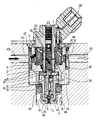
- valve according to the present invention will be described by way of example with reference to the accompanying drawing showing an axial section of the same.
- the valve according to the present invention comprises a supporting body 1 defined by a substantially cylindrical lateral surface 2, and having a first axial cavity 3 housing an electromagnet 4, and an axial hole communicating with said cavity 3.
- Axial hole 6 on electromagnet 4 houses a core 7, while axial hole 5 houses an axially-sliding anchor 8 integral with a mobile plugging member 9.
- Supporting body 1 is fitted with a nozzle 12 in which is formed a fuel outlet hole 13 controlled by plugging member 9.
- plugging member 9 is conveniently integral with a rod 14 sliding axially inside a cylindrical seat 15 on nozzle 12, and guided by a pair of annular projections 16 on which are formed flat portions 17, each defining a fuel passage together with the cylindrical surface of seat 15.
- a spacer 18 is fitted between nozzle 12 and body 1, and nozzle 12 is secured to body 1 by permanently deforming the annular end edge 19 of body 1.
- Anchor 8 is substantially tubular and secured to rod 14, e.g. by permanently deforming the end of anchor 8.
- a helical spring 20 having one end resting on a push rod 22 force-fitted inside an axial hole 23 on core 7, and designed to normally maintain plugging member 9 against a seat 24 upstream from fuel outlet hole 13.
- supporting body 1 presents a series of holes 25 designed to enable external communication of axial hole 5 through lateral surface 2 of body 1. As shown in the drawing, said holes 25 consist of radial holes coming out inside cavity 3 of body 1.
- Spacer 18 presents a slot 30 for connecting axial hole 5 to seat 15 inside nozzle 12 and, consequently, to fuel outlet hole 13.
- the end of rod 14 presents at least one hole 31 for connecting the hole in anchor 8 to seat 15 of nozzle 12.
- body 1 and part of nozzle 12 are conveniently covered by a plastic casing 35 having holes corresponding with holes 25. Between cover and body 1, there is provided a mesh filter 36.
- the valve also comprises known electrical connecting members 38 for supplying electromagnet 4, a cap 39 for nozzle 12, and a sealing ring 40.
- the valve according to the present invention operates as follows.
- the valve according to the present invention When connected to a fuel circuit of the type shown in the drawing, the valve according to the present invention is housed inside a substantially cylindrical seat 45 having a hole 46 communicating with the manifold supplying the mixture to the engine.
- a substantially cylindrical seat 45 having a hole 46 communicating with the manifold supplying the mixture to the engine.
- pressure is exerted on the surface of hole 46 by sealing ring 40 which, together with a further sealing ring 48 between the valve and seat 45, seals the fuel inside seat 45.
- Fuel is fed into seat 45 along a duct 49 preferably located in line with holes 25, and is drained from seat 45 by a further duct 50.
- the fuel supplied by duct 49 is maintained at a pre-determined pressure by a pressure regulator (not shown) on the fuel circuit upstream from duct 49.
- the incoming fuel from duct 49 therefore fills seat 45 and enters the valve through holes 25, as shown by the black and white arrows in the drawing.
- a first stream of fuel through holes 25 flows into cavity 3 and, through the hole in anchor 8 and the openings formed between anchor 8, core 7, body 1, spacer 18 and slot 30, into seat 15 on nozzle 12, and from there through the cavities formed between the flat portions of annular projections 16 and the surface of seat 15 to outlet hole 13.
- a second stream of fuel through holes 25 flows into cavity 3 and, via the openings between core 7, anchor 8 and the surfaces of hole 5 in body 1 and hole 6 in electromagnet 4, flows over the outer surfaces of all the members inside cavity 3 and axial hole 5, and out along duct 50.
- the presence of radial hole 32 in core 7 facilitates said passage.
- Said first stream of fuel therefore substantially supplies outlet hole 13 along said route inside the valve, the reduced length and, consequently, reduced resistance of which provide for minimal load losses, so that the fuel at outlet hole 13 presents substantially the same pressure as inside supply duct 49.
- said second stream of fuel flows through all the openings and holes inside body 1, particularly those at the top of the valve, thus providing for effective scavenging of any vapours formed inside the same.
- valve according to the present invention has been found to overcome the drawbacks typically associated with known substantially axial fuel feed type valves, wherein the metering and atomizing efficiency of the valve is seriously impaired by the formation of vapours particularly at the top of the valve. Moreover, metering and atomizing performance is improved by virtue of the high, substantially constant fuel pressure maintained immediately upstream from outlet hole 13.
Landscapes
- Engineering & Computer Science (AREA)
- Chemical & Material Sciences (AREA)
- Combustion & Propulsion (AREA)
- Mechanical Engineering (AREA)
- General Engineering & Computer Science (AREA)
- Physics & Mathematics (AREA)
- Electromagnetism (AREA)
- Fuel-Injection Apparatus (AREA)
Applications Claiming Priority (2)
| Application Number | Priority Date | Filing Date | Title |
|---|---|---|---|
| IT67589/88A IT1219396B (it) | 1988-06-23 | 1988-06-23 | Valvola per la dosatura e la polverizzazione di carburante ad azionamento elettromagnetico provvista di fori laterali di ingresso del carburante |
| IT6758988 | 1988-06-23 |
Publications (2)
| Publication Number | Publication Date |
|---|---|
| EP0347914A1 true EP0347914A1 (de) | 1989-12-27 |
| EP0347914B1 EP0347914B1 (de) | 1994-03-02 |
Family
ID=11303672
Family Applications (1)
| Application Number | Title | Priority Date | Filing Date |
|---|---|---|---|
| EP89111393A Expired - Lifetime EP0347914B1 (de) | 1988-06-23 | 1989-06-22 | Elektromagnetisches Kraftstoffdosier- und Kraftstoffzerstäubungsventil |
Country Status (4)
| Country | Link |
|---|---|
| EP (1) | EP0347914B1 (de) |
| DE (1) | DE68913368T2 (de) |
| ES (1) | ES2051932T3 (de) |
| IT (1) | IT1219396B (de) |
Cited By (2)
| Publication number | Priority date | Publication date | Assignee | Title |
|---|---|---|---|---|
| US5168857A (en) * | 1990-11-19 | 1992-12-08 | Ford Motor Company | Integrally formed fuel rail/injectors and method for producing |
| US8434457B2 (en) | 2010-06-29 | 2013-05-07 | Caterpillar Inc. | System and method for cooling fuel injectors |
Citations (6)
| Publication number | Priority date | Publication date | Assignee | Title |
|---|---|---|---|---|
| FR2553834A1 (fr) * | 1983-10-20 | 1985-04-26 | Sibe | Soupape d'injection pour moteur a combustion interne |
| EP0232475A1 (de) * | 1986-01-31 | 1987-08-19 | VDO Adolf Schindling AG | Elektromagnetisch betätigbares Kraftstoffeinspritzventil |
| GB2187332A (en) * | 1986-02-19 | 1987-09-03 | Weber Srl | Electromagnetic fuel metering and atomizing valve |
| GB2196181A (en) * | 1984-03-05 | 1988-04-20 | Gerhard Mesenich | Electromagnetic injection valve |
| GB2198589A (en) * | 1986-11-15 | 1988-06-15 | Hitachi Ltd | Electromagnetic fuel injectors |
| FR2616485A1 (fr) * | 1987-06-09 | 1988-12-16 | Weber Srl | Valve d'atomisation et dosage de carburant pour un dispositif d'injection de carburant d'un moteur a combustion interne |
-
1988
- 1988-06-23 IT IT67589/88A patent/IT1219396B/it active
-
1989
- 1989-06-22 DE DE68913368T patent/DE68913368T2/de not_active Expired - Fee Related
- 1989-06-22 ES ES89111393T patent/ES2051932T3/es not_active Expired - Lifetime
- 1989-06-22 EP EP89111393A patent/EP0347914B1/de not_active Expired - Lifetime
Patent Citations (6)
| Publication number | Priority date | Publication date | Assignee | Title |
|---|---|---|---|---|
| FR2553834A1 (fr) * | 1983-10-20 | 1985-04-26 | Sibe | Soupape d'injection pour moteur a combustion interne |
| GB2196181A (en) * | 1984-03-05 | 1988-04-20 | Gerhard Mesenich | Electromagnetic injection valve |
| EP0232475A1 (de) * | 1986-01-31 | 1987-08-19 | VDO Adolf Schindling AG | Elektromagnetisch betätigbares Kraftstoffeinspritzventil |
| GB2187332A (en) * | 1986-02-19 | 1987-09-03 | Weber Srl | Electromagnetic fuel metering and atomizing valve |
| GB2198589A (en) * | 1986-11-15 | 1988-06-15 | Hitachi Ltd | Electromagnetic fuel injectors |
| FR2616485A1 (fr) * | 1987-06-09 | 1988-12-16 | Weber Srl | Valve d'atomisation et dosage de carburant pour un dispositif d'injection de carburant d'un moteur a combustion interne |
Non-Patent Citations (4)
| Title |
|---|
| PATENT ABSTRACTS OF JAPAN, Vol. 10, No. 138 (M-480)(2195) 21 May 1986; & JP,A,60 261 972 (MITSUBISHI JIDOSHA KOGYO) 25 December 1985, the whole document. * |
| PATENT ABSTRACTS OF JAPAN, Vol. 11, No. 397 (M-655)(2844) 25 December 1987; & JP,A,62 162 769 (HITACHI) 25 December 1985, the whole document. * |
| PATENT ABSTRACTS OF JAPAN, Vol. 9, No. 121 (M-382)(1844) 25 May 1985; & JP,A,60 006 065 (JIDOSHA KOGAI ANZEN KIKI GIJUTSU KENKYU KUMIAI) 12 January 1985, the whole document. * |
| PATENT ABSTRACTS OF JAPAN, Vol. 9, No. 220 (E-341)(1943) 06 September 1985; & JP,A,60 079 154 (NIPPON DENSO) 04 May 1985, the whole document. * |
Cited By (3)
| Publication number | Priority date | Publication date | Assignee | Title |
|---|---|---|---|---|
| US5168857A (en) * | 1990-11-19 | 1992-12-08 | Ford Motor Company | Integrally formed fuel rail/injectors and method for producing |
| US8434457B2 (en) | 2010-06-29 | 2013-05-07 | Caterpillar Inc. | System and method for cooling fuel injectors |
| DE112011102211B4 (de) | 2010-06-29 | 2019-01-03 | Caterpillar Inc. | System und Verfahren zum Kühlen von Brennstoffeinspritzvorrichtungen |
Also Published As
| Publication number | Publication date |
|---|---|
| ES2051932T3 (es) | 1994-07-01 |
| EP0347914B1 (de) | 1994-03-02 |
| DE68913368D1 (de) | 1994-04-07 |
| IT1219396B (it) | 1990-05-11 |
| DE68913368T2 (de) | 1994-06-01 |
| IT8867589A0 (it) | 1988-06-23 |
Similar Documents
| Publication | Publication Date | Title |
|---|---|---|
| US4395988A (en) | Fuel injection system | |
| US5060868A (en) | Electromagnetically actuatable valve | |
| US4763635A (en) | Discharge system for introducing volatilized fuel into an internal combustion engine | |
| US5758865A (en) | Fuel injection valve and engine including the same | |
| US5884850A (en) | Fuel injection valve | |
| CZ20022963A3 (en) | Fuel injection valve with a filter bush | |
| US5018501A (en) | Electromagnetic fuel injection valve apparatus | |
| US5348233A (en) | High volume gaseous fuel injector | |
| US5934252A (en) | Fuel injection system | |
| EP0571418A1 (de) | Magnetventilgesteuerte Tankreinigungsvorrichtung mit einer Verbesserung für langsame Motordrehzahl. | |
| GB1076184A (en) | Fuel injectors for internal combustion engines | |
| US4678124A (en) | Electromagnetically actuatable valve in particular a fuel injection valve | |
| US3247833A (en) | Fuel injection valves | |
| EP0347916A1 (de) | Elektromagnetisches Kraftstoffdosier- und Kraftstoffzerstäubungsventil | |
| US4455982A (en) | Electromagnetically actuatable valve | |
| JPS5884281A (ja) | 電磁操作弁 | |
| US5673853A (en) | Electromagnetic fuel injector control valve | |
| CZ20023456A3 (en) | Fuel injection valve | |
| US5641126A (en) | Fuel injection systems with compact filter mountings | |
| US4648559A (en) | Electromagnetically actuatable fluid valve | |
| US6764031B2 (en) | Fuel injection valve | |
| US5676345A (en) | Electromagnetic valve | |
| US4317542A (en) | Fuel injector | |
| EP0347914A1 (de) | Elektromagnetisches Kraftstoffdosier- und Kraftstoffzerstäubungsventil | |
| US20040026541A1 (en) | Fuel injection valve |
Legal Events
| Date | Code | Title | Description |
|---|---|---|---|
| PUAI | Public reference made under article 153(3) epc to a published international application that has entered the european phase |
Free format text: ORIGINAL CODE: 0009012 |
|
| AK | Designated contracting states |
Kind code of ref document: A1 Designated state(s): DE ES FR GB SE |
|
| 17P | Request for examination filed |
Effective date: 19900529 |
|
| 17Q | First examination report despatched |
Effective date: 19910513 |
|
| GRAA | (expected) grant |
Free format text: ORIGINAL CODE: 0009210 |
|
| AK | Designated contracting states |
Kind code of ref document: B1 Designated state(s): DE ES FR GB SE |
|
| PG25 | Lapsed in a contracting state [announced via postgrant information from national office to epo] |
Ref country code: SE Free format text: THE PATENT HAS BEEN ANNULLED BY A DECISION OF A NATIONAL AUTHORITY Effective date: 19940302 |
|
| REF | Corresponds to: |
Ref document number: 68913368 Country of ref document: DE Date of ref document: 19940407 |
|
| PGFP | Annual fee paid to national office [announced via postgrant information from national office to epo] |
Ref country code: GB Payment date: 19940617 Year of fee payment: 6 |
|
| PGFP | Annual fee paid to national office [announced via postgrant information from national office to epo] |
Ref country code: FR Payment date: 19940629 Year of fee payment: 6 Ref country code: ES Payment date: 19940629 Year of fee payment: 6 |
|
| ET | Fr: translation filed | ||
| REG | Reference to a national code |
Ref country code: ES Ref legal event code: FG2A Ref document number: 2051932 Country of ref document: ES Kind code of ref document: T3 |
|
| PGFP | Annual fee paid to national office [announced via postgrant information from national office to epo] |
Ref country code: DE Payment date: 19940830 Year of fee payment: 6 |
|
| PLBE | No opposition filed within time limit |
Free format text: ORIGINAL CODE: 0009261 |
|
| STAA | Information on the status of an ep patent application or granted ep patent |
Free format text: STATUS: NO OPPOSITION FILED WITHIN TIME LIMIT |
|
| 26N | No opposition filed | ||
| PG25 | Lapsed in a contracting state [announced via postgrant information from national office to epo] |
Ref country code: GB Effective date: 19950622 |
|
| PG25 | Lapsed in a contracting state [announced via postgrant information from national office to epo] |
Ref country code: ES Free format text: LAPSE BECAUSE OF THE APPLICANT RENOUNCES Effective date: 19950623 |
|
| GBPC | Gb: european patent ceased through non-payment of renewal fee |
Effective date: 19950622 |
|
| PG25 | Lapsed in a contracting state [announced via postgrant information from national office to epo] |
Ref country code: DE Effective date: 19960301 |
|
| REG | Reference to a national code |
Ref country code: ES Ref legal event code: FD2A Effective date: 19991007 |
|
| PG25 | Lapsed in a contracting state [announced via postgrant information from national office to epo] |
Ref country code: FR Free format text: LAPSE BECAUSE OF NON-PAYMENT OF DUE FEES Effective date: 19950630 |