EP0347836A2 - Lamp replacement tool - Google Patents
Lamp replacement tool Download PDFInfo
- Publication number
- EP0347836A2 EP0347836A2 EP89111200A EP89111200A EP0347836A2 EP 0347836 A2 EP0347836 A2 EP 0347836A2 EP 89111200 A EP89111200 A EP 89111200A EP 89111200 A EP89111200 A EP 89111200A EP 0347836 A2 EP0347836 A2 EP 0347836A2
- Authority
- EP
- European Patent Office
- Prior art keywords
- tool
- lamp
- blade
- upper blade
- flange
- Prior art date
- Legal status (The legal status is an assumption and is not a legal conclusion. Google has not performed a legal analysis and makes no representation as to the accuracy of the status listed.)
- Withdrawn
Links
Images

Classifications
-
- H—ELECTRICITY
- H01—ELECTRIC ELEMENTS
- H01K—ELECTRIC INCANDESCENT LAMPS
- H01K3/00—Apparatus or processes adapted to the manufacture, installing, removal, or maintenance of incandescent lamps or parts thereof
- H01K3/32—Auxiliary devices for cleaning, placing, or removing incandescent lamps
-
- Y—GENERAL TAGGING OF NEW TECHNOLOGICAL DEVELOPMENTS; GENERAL TAGGING OF CROSS-SECTIONAL TECHNOLOGIES SPANNING OVER SEVERAL SECTIONS OF THE IPC; TECHNICAL SUBJECTS COVERED BY FORMER USPC CROSS-REFERENCE ART COLLECTIONS [XRACs] AND DIGESTS
- Y10—TECHNICAL SUBJECTS COVERED BY FORMER USPC
- Y10T—TECHNICAL SUBJECTS COVERED BY FORMER US CLASSIFICATION
- Y10T29/00—Metal working
- Y10T29/53—Means to assemble or disassemble
- Y10T29/5313—Means to assemble electrical device
- Y10T29/53257—Means comprising hand-manipulatable implement
-
- Y—GENERAL TAGGING OF NEW TECHNOLOGICAL DEVELOPMENTS; GENERAL TAGGING OF CROSS-SECTIONAL TECHNOLOGIES SPANNING OVER SEVERAL SECTIONS OF THE IPC; TECHNICAL SUBJECTS COVERED BY FORMER USPC CROSS-REFERENCE ART COLLECTIONS [XRACs] AND DIGESTS
- Y10—TECHNICAL SUBJECTS COVERED BY FORMER USPC
- Y10T—TECHNICAL SUBJECTS COVERED BY FORMER US CLASSIFICATION
- Y10T29/00—Metal working
- Y10T29/53—Means to assemble or disassemble
- Y10T29/53274—Means to disassemble electrical device
- Y10T29/53283—Means comprising hand-manipulatable implement
Definitions
- This invention relates to a lamp replacement tool and more particularly to a lamp replacement tool useful in replacing miniature lamps used in aircraft cockpit control panels.
- Some aircraft cockpit control panels are designed with lighted push button switches having the push buttons mounted flush with the front of the control panel so as to avoid inadvertent switch actuations. Switches of this type, are typically, provided with the push button including a display having a legend indicative of the control function of the switch. Some display type switches are available which include legends visible in direct sunlight upon depression of the push button and invisible before push button depression.
- the push button portion of the switch includes the lamp housing which unplugs from the switch body and hinges down to expose the lamp for replacement. A friction fit maintains the lamp in the lamp housing.
- a typical switch of the type described is the Mark 15 P/N 10732 provided by Jay-El Products Inc., 1859 West 169th Street, Gardena, California and a typical miniature lamp is the American National Standards Institute lamp number 6839 available from Oak Switch Systems Inc., P.O. Box 517, Crystal Lake, Illinois.
- the present invention encompasses a lamp replacement tool for use in replacing lamps from or into a lamp housing.
- the lamp is of the type which includes a bulb portion through which light is emitted, a base portion having one end adjacent the bulb portion, and a base contact protruding from another end of the base portion.
- the lamp base portion is provided with a circular flange formed on the base portion intermediate of the ends of the base portion.
- the lamp replacement tool includes a handle member and upper and lower blades extending in the same direction from one end of the handle member in parallel relationship to each other.
- the lower blade is formed with forked end portion having a u-shape dimensioned so as to embrace the lamp base portion and engage the flange.
- the upper blade is formed with a v-shaped portion wherein the v-shape is inverted relative to the lower blade and the apex of the v-shape is aligned over the center of the radius of the u-shaped end of the lower blade.
- the v-shaped portion of the upper blade is dimensioned so as to have the interior surfaces of the v-shape contact the peripheral surfaces of the lamp base contact. The lamp is held between the forked and v-shaped portions thereby captivating the lamp securely between the upper and lower blades.
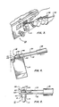
- a lamp replacement tool 10, shown in Fig. 1A may be used for removing or inserting a lamp 12 (see Fig. 5), from or into a lamp housing 14 as shown in Fig. 4.
- the lamp 12 includes a bulb portion 15, a base portion 16, having opposite ends 18, 20, and a flange portion 22 at a location intermediate of ends 18, 20.
- End 20 includes a base contact 24 protruding therefrom and spaced from flange 22.
- the lamp replacement tool 10, Figure 1A includes an elongated handle member 26 having ends 28, 30, a lower blade 32 and an upper blade 34 extending from end 28 and a pry-blade 36 extending from end 30.
- the handle member 26, Figure 1A is shown as a generally cylindrically-shaped member preferably made of injected molded of ABS thermoplastic, a common thermoplastic used in the injection molding process.
- ABS thermoplastic a common thermoplastic used in the injection molding process.
- other convenient shapes, materials, or methods of manufacture can be utilized in making handle member 26, such as, for example, a wood or metal.
- both lower blade 32 and upper blade 34 are constructed of flat full hard 301 stainless steel sheet metal approximately 6,25mm wide with the lower blade 32 having a thickness of 0,4 mm and upper blade 36 having a thickness of 0,25 mm selected to provide flexibility.
- the lower blade 32 extends from end 28 of handle member 26 and includes a means for engaging base portion 16, Figure 5 and flange 22 comprising a u-shaped or forked end portion 38, Figure 1B having a pair of legs 40 formed with chamfered ends 42 useful for initiating the lifting of lamp 12 from housing 14.
- the forked end portion 38 is the form of a u-shape 41 dimensioned so as to embrace the lamp base portion 16 and engage with the base portion flange 22.
- the upper blade 34 extends from end 28 of handle member 26 in spaced apart parallel relationship to lower blade 32.
- Upper blade 34 includes a v-shaped portion 44 with the apex 45 of the "V" formed transverse to the width axis of the upper blade 34.
- the interior surfaces 46 of the "V" shape face the lower blade 32.
- the apex 45 is aligned in the longitudinal direction with the center of radius of u-shaped portion 41.
- the upper blade 34 terminates with an angled lead-in 48 extending from the outward-most leg of the v-shape portion 44.
- the pry-blade 36 extends from end 30 of handle member 26 and in the present embodiment of the invention is constructed from 3,125 mm diameter 304 stainless steel rod.
- the distal end 50 of pry-blade 36 is wedge-shaped and resembles the shape of a flatten screw driver blade.
- the pry-blade 36 is used to unplug the housing 14 from a switch body (not shown) located in switch panel 52 and to pivot the lamp housing 14, Figure 2, from the switch panel 52 by prying lamp housing 14 into the pivoted open position shown in Figures 3, 4.
- a switch body not shown
- the lamp housing 14 With the lamp housing 14 in the open position one of the chamfered tips 42 of lower blade 32 is inserted between the flange 22 and housing 14 and the tool 10 is rotated approximately ninety (90) degrees so as to engage the other chamfered tip 42 between the flange 22 and lamp housing 14.
- Now enough clearance is provided to slide the forked portion 38 under the flange 22 while pushing the tool 10 forward in the direction of the lamp 12 until the arcuate surface 41 contacts and embraces the base portion 16 of lamp 12.
- the lower blade 32 supports the lamp 12 while the lead-in 48 provides a smooth surface for the upper blade 34 to slide and flex up and over base contact 24.
- the lead-in 48 slides up and over base contact 24 the interior surfaces 46 of v-shaped portion 44 engage with the peripheral surfaces of base contact 24.
- the lamp 12 is now held between the v-shaped and forked portions 44 and 38 of the upper and lower blades 34 and 32, thereby locking and captivating the lamp 12 between the upper and lower blades 34 and 32 respectively.
- the captivated lamp 12 can now be safely removed from housing 14 by lifting the tool 10 away from the lamp housing 14.
- the replacement lamp 12 can be grasped between the thumb and forefinger of one hand while the tool 10 is pushed onto the lamp 12 with the other hand as described above. Once the lamp 12 is captivated between the upper and lower blades 34 and 32 as previously described the lamp 12 can be inserted in the he lamp housing 14 and the tool 10 can now be withdrawn.
- FIG. 1D An alternate construction of the tool 10 is shown as a tool 10A in Figure 1D.
- an upper blade 35 includes an aperture 43 the center of which coincides with the center-of-radius of u-shaped portion 41 in lower blade 32, Figure 1B.
- the diameter of aperture 43, Figure 1D is selected, to provide an interference fit around the peripheral surfaces of rounded base contact 24 Figure 4.
- the upper blade 35 terminates in an angled lead-in 47, Figure 1D. Angled lead-in 47 performs the same function in use as lead-in 48, Figure 1B.
- tool 10A differs only slightly from the use of tool 10, Figure 1A. Namely, as the tool 10A is pushed onto lamp 12 lead-in 47 flexes and slides up and over base contact 24 as does lead-in 48 of tool 10. The tool 10A continues to be moved across base contact 24 and stops with the interior peripheral surfaces of aperture 43 engaged with the peripheral surface of base contact 24 thereby captivating or locking lamp 12 between upper and lower blades 35 and 32 respectively previously described.
- the installation of lamp 12 with tool 10A also differs slightly from that with the use of tool 10. Namely, in order to withdraw tool 10A after installing lamp 12 into lamp housing 14 it may be necessary to lift upper blade 34 slightly in order to clear the peripheral surfaces of aperture 43 from base contact 24.
- an advantage of this invention is in providing a tool for securely replacing lamps.
- Another advantage of this invention is in providing a lamp replacement tool that minimizes the likelihood of dropping lamps during the replacement process.
- a further advantage of this invention is in providing an improved lamp replacement tool which is simple and easy to use and which positively captivates the lamp for removal or insertion into the lamp housing.
Landscapes
- Engineering & Computer Science (AREA)
- Manufacturing & Machinery (AREA)
- Knives (AREA)
- Switch Cases, Indication, And Locking (AREA)
- Push-Button Switches (AREA)
Abstract
Description
- This invention relates to a lamp replacement tool and more particularly to a lamp replacement tool useful in replacing miniature lamps used in aircraft cockpit control panels.
- Some aircraft cockpit control panels are designed with lighted push button switches having the push buttons mounted flush with the front of the control panel so as to avoid inadvertent switch actuations. Switches of this type, are typically, provided with the push button including a display having a legend indicative of the control function of the switch. Some display type switches are available which include legends visible in direct sunlight upon depression of the push button and invisible before push button depression. The push button portion of the switch includes the lamp housing which unplugs from the switch body and hinges down to expose the lamp for replacement. A friction fit maintains the lamp in the lamp housing. A typical switch of the type described is the Mark 15 P/N 10732 provided by Jay-El Products Inc., 1859 West 169th Street, Gardena, California and a typical miniature lamp is the American National Standards Institute lamp number 6839 available from Oak Switch Systems Inc., P.O. Box 517, Crystal Lake, Illinois.
- The type of switch described above was designed with the intention that the lamp replacement could be accomplished manually without tools. However, experience has shown that due to the miniature size of the lamps and the tight quarters in the aircraft cockpit environment difficulties were encountered in manually extracting the lamp from the lamp housing. Because of these tight quarters, problems have been encountered which include the dropping of lamps with the result of time lost in attempting to recover the dropped lamps. A more serious problem occurs when the lamp is dropped into the interior of the switch sometimes requiring the removal of the control panel in order to retrieve the lamp from the switch interior.
- To overcome the forgoing problems attempts have been made to replace lamps using readily available tools such as various styles of screw drivers in conjunction with fingers or pliers or tweezers to extract the lamp from the housing. However, such attempts have met with erratic success and the forgoing problems continue to exist.
- The present invention encompasses a lamp replacement tool for use in replacing lamps from or into a lamp housing. The lamp is of the type which includes a bulb portion through which light is emitted, a base portion having one end adjacent the bulb portion, and a base contact protruding from another end of the base portion. The lamp base portion is provided with a circular flange formed on the base portion intermediate of the ends of the base portion.
- The lamp replacement tool includes a handle member and upper and lower blades extending in the same direction from one end of the handle member in parallel relationship to each other. The lower blade is formed with forked end portion having a u-shape dimensioned so as to embrace the lamp base portion and engage the flange. The upper blade is formed with a v-shaped portion wherein the v-shape is inverted relative to the lower blade and the apex of the v-shape is aligned over the center of the radius of the u-shaped end of the lower blade. The v-shaped portion of the upper blade is dimensioned so as to have the interior surfaces of the v-shape contact the peripheral surfaces of the lamp base contact. The lamp is held between the forked and v-shaped portions thereby captivating the lamp securely between the upper and lower blades.
- Further advantages and details of my invention can be had from the following description and claims taken together with the accompanying drawing.
- In the drawing:
- Figure 1A is a perspective view of the lamp replacement tool of the present invention;
- Figure 1B is a partial perspective view of the lamp replacement tool of the present invention showing the upper and lower blades,
- Figure 1C is a partial perspective view of the lamp replacement tool of the present invention showing the pry-blade;
- Figure 1D is a partial perspective view of an alternate lamp replacement tool showing a modified upper blade;
- Figure 2 is a perspective view of a portion of a typical cockpit control panel showing the pry-blade in use;
- Figure 3 is a perspective view of a portion of a typical cockpit control panel showing the lamp replacement tool in use;
- Figure 4 is a side view of the lamp housing and a partial side view of the lamp replacement tool of the present invention in use; and
- Figure 5 is a partial side view of the lamp replacement tool with the lamp captivated between the upper and lower blades.
- A
lamp replacement tool 10, shown in Fig. 1A may be used for removing or inserting a lamp 12 (see Fig. 5), from or into alamp housing 14 as shown in Fig. 4. Thelamp 12 includes abulb portion 15, abase portion 16,
havingopposite ends flange portion 22 at a location intermediate ofends End 20 includes abase contact 24 protruding therefrom and spaced fromflange 22. - The
lamp replacement tool 10, Figure 1A, includes anelongated handle member 26 havingends lower blade 32 and anupper blade 34 extending fromend 28 and a pry-blade 36 extending fromend 30. - The
handle member 26, Figure 1A, is shown as a generally cylindrically-shaped member preferably made of injected molded of ABS thermoplastic, a common thermoplastic used in the injection molding process. However, other convenient shapes, materials, or methods of manufacture can be utilized in makinghandle member 26, such as, for example, a wood or metal. - In the present embodiment of the invention both
lower blade 32 andupper blade 34 are constructed of flat full hard 301 stainless steel sheet metal approximately 6,25mm wide with thelower blade 32 having a thickness of 0,4 mm andupper blade 36 having a thickness of 0,25 mm selected to provide flexibility. - The
lower blade 32, Figure 1B, extends fromend 28 ofhandle member 26 and includes a means forengaging base portion 16, Figure 5 andflange 22 comprising a u-shaped or forkedend portion 38, Figure 1B having a pair oflegs 40 formed withchamfered ends 42 useful for initiating the lifting oflamp 12 fromhousing 14. The forkedend portion 38 is the form of au-shape 41 dimensioned so as to embrace thelamp base portion 16 and engage with thebase portion flange 22. - The
upper blade 34, Figure 1B, extends fromend 28 ofhandle member 26 in spaced apart parallel relationship tolower blade 32.Upper blade 34 includes a v-shaped portion 44 with theapex 45 of the "V" formed transverse to the width axis of theupper blade 34. Theinterior surfaces 46 of the "V" shape face thelower blade 32. Theapex 45 is aligned in the longitudinal direction with the center of radius ofu-shaped portion 41. Theupper blade 34 terminates with an angled lead-in 48 extending from the outward-most leg of the v-shape portion 44. - The pry-
blade 36, Figure 1C, extends fromend 30 ofhandle member 26 and in the present embodiment of the invention is constructed from 3,125 mm diameter 304 stainless steel rod. Thedistal end 50 of pry-blade 36 is wedge-shaped and resembles the shape of a flatten screw driver blade. - In use of the
lamp replacement tool 10 the pry-blade 36 is used to unplug thehousing 14 from a switch body (not shown) located inswitch panel 52 and to pivot thelamp housing 14, Figure 2, from theswitch panel 52 by pryinglamp housing 14 into the pivoted open position shown in Figures 3, 4. With the lamp housing 14 in the open position one of thechamfered tips 42 oflower blade 32 is inserted between theflange 22 andhousing 14 and thetool 10 is rotated approximately ninety (90) degrees so as to engage the other chamferedtip 42 between theflange 22 andlamp housing 14. Now enough clearance is provided to slide the forkedportion 38 under theflange 22 while pushing thetool 10 forward in the direction of thelamp 12 until thearcuate surface 41 contacts and embraces thebase portion 16 oflamp 12. - As the
tool 10 is pushed onto thelamp 12 thelower blade 32 supports thelamp 12 while the lead-in 48 provides a smooth surface for theupper blade 34 to slide and flex up and overbase contact 24. As the lead-in 48 slides up and over base contact 24 theinterior surfaces 46 of v-shaped portion 44 engage with the peripheral surfaces ofbase contact 24. Thelamp 12 is now held between the v-shaped and forkedportions lower blades lamp 12 between the upper andlower blades lamp 12 can now be safely removed fromhousing 14 by lifting thetool 10 away from thelamp housing 14. - To install a
replacement lamp 12, thereplacement lamp 12 can be grasped between the thumb and forefinger of one hand while thetool 10 is pushed onto thelamp 12 with the other hand as described above. Once thelamp 12 is captivated between the upper andlower blades lamp 12 can be inserted in the helamp housing 14 and thetool 10 can now be withdrawn. - An alternate construction of the
tool 10 is shown as a tool 10A in Figure 1D. In this construction anupper blade 35 includes anaperture 43 the center of which coincides with the center-of-radius ofu-shaped portion 41 inlower blade 32, Figure 1B. The diameter ofaperture 43, Figure 1D is selected, to provide an interference fit around the peripheral surfaces ofrounded base contact 24 Figure 4. As is the case withupper blade 34, Figure 1B, theupper blade 35 terminates in an angled lead-in 47, Figure 1D. Angled lead-in 47 performs the same function in use as lead-in 48, Figure 1B. - The use of tool 10A, Figure 1D, differs only slightly from the use of
tool 10, Figure 1A. Namely, as the tool 10A is pushed ontolamp 12 lead-in 47 flexes and slides up and overbase contact 24 as does lead-in 48 oftool 10. The tool 10A continues to be moved acrossbase contact 24 and stops with the interior peripheral surfaces ofaperture 43 engaged with the peripheral surface ofbase contact 24 thereby captivating or lockinglamp 12 between upper andlower blades - The installation of
lamp 12 with tool 10A also differs slightly from that with the use oftool 10. Namely, in order to withdraw tool 10A after installinglamp 12 intolamp housing 14 it may be necessary to liftupper blade 34 slightly in order to clear the peripheral surfaces ofaperture 43 frombase contact 24. - As will now be understood, the present invention has many advantages in use. Accordingly, an advantage of this invention is in providing a tool for securely replacing lamps. Another advantage of this invention is in providing a lamp replacement tool that minimizes the likelihood of dropping lamps during the replacement process. A further advantage of this invention is in providing an improved lamp replacement tool which is simple and easy to use and which positively captivates the lamp for removal or insertion into the lamp housing.
Claims (11)
Applications Claiming Priority (2)
| Application Number | Priority Date | Filing Date | Title |
|---|---|---|---|
| US209711 | 1988-06-22 | ||
| US07/209,711 US4852925A (en) | 1988-06-22 | 1988-06-22 | Lamp replacement tool |
Publications (2)
| Publication Number | Publication Date |
|---|---|
| EP0347836A2 true EP0347836A2 (en) | 1989-12-27 |
| EP0347836A3 EP0347836A3 (en) | 1990-07-25 |
Family
ID=22779942
Family Applications (1)
| Application Number | Title | Priority Date | Filing Date |
|---|---|---|---|
| EP89111200A Withdrawn EP0347836A3 (en) | 1988-06-22 | 1989-06-20 | Lamp replacement tool |
Country Status (4)
| Country | Link |
|---|---|
| US (1) | US4852925A (en) |
| EP (1) | EP0347836A3 (en) |
| JP (1) | JPH0233852A (en) |
| CA (1) | CA1304966C (en) |
Cited By (2)
| Publication number | Priority date | Publication date | Assignee | Title |
|---|---|---|---|---|
| GB2362599A (en) * | 2000-05-25 | 2001-11-28 | Warren Anthony Talbot | Universal indicating lamp installation / removal tool |
| US10228704B2 (en) | 2017-01-16 | 2019-03-12 | International Business Machines Corporation | Unmanned vehicle for servicing equipment |
Families Citing this family (40)
| Publication number | Priority date | Publication date | Assignee | Title |
|---|---|---|---|---|
| US4920637A (en) * | 1989-09-28 | 1990-05-01 | Porta Systems Corp. | Wire insertion and removal tool with module removal means |
| USD335803S (en) | 1991-02-01 | 1993-05-25 | Yazaki Corporation | Tool for disengaging an electrical connector terminal |
| US5187851A (en) * | 1991-12-13 | 1993-02-23 | Itt Corporation | O.D. - I.D. combination release tool |
| US5440803A (en) * | 1993-05-17 | 1995-08-15 | Cyrix Corporation | Integrated circuit extraction tool |
| US5617628A (en) * | 1993-05-17 | 1997-04-08 | Cyrix Corporation | Integrated circuit extraction tool |
| USD355573S (en) | 1993-06-11 | 1995-02-21 | Raymond Ortiz | Light bulb extractor |
| US5394313A (en) * | 1993-10-01 | 1995-02-28 | General Motors Corporation | Lamp assembly with integral bulb replacement tool |
| US5685761A (en) * | 1995-09-27 | 1997-11-11 | Schepens; Clyde R. | Multi-purpose lamp fixture tool |
| US5799382A (en) * | 1996-03-27 | 1998-09-01 | Brameyer; Richard K. | Miniature lamp holder extraction device |
| US6249960B1 (en) | 1996-12-31 | 2001-06-26 | Berg Technology, Inc. | Tool for manipulating an electrical connector and method of use |
| US6029341A (en) * | 1997-06-23 | 2000-02-29 | The Whitaker Corporation | Latch tool for electrical connector |
| US6401571B1 (en) * | 2000-12-15 | 2002-06-11 | Smiths Industries Aerospace & Defense Systems, Inc. | Lamp module removal and installation tool |
| US6870114B2 (en) * | 2001-03-12 | 2005-03-22 | Joseph W. Cole | Method and apparatus for removing and replacing bulb of push-button type electrical switch |
| US6739220B1 (en) | 2002-08-12 | 2004-05-25 | Wagic, Inc. | Motorized light bulb changer |
| US7631579B2 (en) | 2002-08-12 | 2009-12-15 | Wagic, Inc. | Customizable light bulb changer |
| US7143668B2 (en) | 2002-08-12 | 2006-12-05 | Wagic, Inc. | Customizable light bulb changer |
| US7255024B2 (en) * | 2002-08-12 | 2007-08-14 | Wagic, Inc. | Customizable light bulb changer with suction cup and control |
| US6883400B2 (en) | 2002-08-12 | 2005-04-26 | Norio Sugano | Light bulb changer |
| US6893066B1 (en) * | 2002-08-27 | 2005-05-17 | The Antioch Company | Combination tool for transferring labels and appliques |
| US6976303B2 (en) * | 2002-10-24 | 2005-12-20 | Molex Incorporated | System and tool for mounting a connecting device to a substrate |
| US20040216562A1 (en) * | 2003-04-29 | 2004-11-04 | Ireland Daniel T. | Bulb replacement tool |
| US7035519B2 (en) * | 2003-05-02 | 2006-04-25 | Panduit Corp. | Fiber optic connector removal tool |
| US7413228B2 (en) * | 2003-05-05 | 2008-08-19 | Kam Por Paul Tong | Hard flex tweezers |
| US20050035614A1 (en) * | 2003-08-11 | 2005-02-17 | Ralph Wessel | Light bulb puller |
| US20050220599A1 (en) * | 2004-04-02 | 2005-10-06 | Job Matthew A | Clamshell and fork-style material handling apparatus |
| US7107873B2 (en) * | 2004-04-06 | 2006-09-19 | Stratitec Inc. | Inkjet cartridge top remover and method |
| US6976407B1 (en) * | 2005-03-30 | 2005-12-20 | Alden Corporation | Broken bulb remover |
| US7814634B2 (en) * | 2005-07-13 | 2010-10-19 | Alcatel-Lucent Usa Inc. | Electrical connector extraction and/or insertion tool |
| GB2437530B (en) * | 2006-04-03 | 2011-11-16 | Gibcloser Ltd | Fitting tool for a concealed door closer |
| US20080196244A1 (en) * | 2007-02-16 | 2008-08-21 | Miglin David R | Electrical outlet cover remover |
| US7770249B2 (en) * | 2007-10-12 | 2010-08-10 | K & S Wiring Systems Inc. | Wiring harness tooling device |
| US20110000062A1 (en) * | 2009-07-02 | 2011-01-06 | Raymond Kolasa | Christmas mini light bulb remover |
| US8516925B2 (en) | 2009-09-17 | 2013-08-27 | Wagic, Inc. | Extendable multi-tool including interchangable light bulb changer and accessories |
| US8627561B2 (en) * | 2012-02-29 | 2014-01-14 | GM Global Technology Operations LLC | Lamp socket assembly tool |
| TWI498520B (en) * | 2012-06-29 | 2015-09-01 | Ibm | Apparatus and method for detaching a component from a mounting surface |
| US8875600B1 (en) | 2012-08-01 | 2014-11-04 | Paul M. Ely | Spiral light bulb changing device |
| US9492914B2 (en) * | 2013-05-06 | 2016-11-15 | Ciena Corporation | Optical interface insertion and extraction tool |
| US20140357106A1 (en) * | 2013-05-30 | 2014-12-04 | Mellanox Technologies Ltd. | Connector extraction tool |
| USD723346S1 (en) * | 2013-08-16 | 2015-03-03 | Osram Sylvania Inc. | Connector release tool |
| US9070544B1 (en) | 2014-06-04 | 2015-06-30 | Snatcher, LLC | Light bulb installation and removal tool |
Family Cites Families (9)
| Publication number | Priority date | Publication date | Assignee | Title |
|---|---|---|---|---|
| US251182A (en) * | 1881-12-20 | Watch-maker s and jeweler s tool | ||
| US1023077A (en) * | 1911-06-26 | 1912-04-09 | Robert C Grout | Fuse-changer. |
| US1244475A (en) * | 1913-09-11 | 1917-10-30 | Kellogg Switchboard & Supply | Switchboard-lamp. |
| US1641252A (en) * | 1924-11-01 | 1927-09-06 | Dickey Alexander | End wrench |
| US2184074A (en) * | 1938-09-09 | 1939-12-19 | Bell Telephone Labor Inc | Hand tool |
| US2608433A (en) * | 1945-06-06 | 1952-08-26 | Marbeuf Armand Jean | Tongs for test tubes or the like |
| US2802211A (en) * | 1956-03-14 | 1957-08-13 | Friedman Max | Fastener holding device |
| US3214210A (en) * | 1963-01-30 | 1965-10-26 | Harry P Keirn | Tube handler |
| DE7627555U1 (en) * | 1976-09-03 | 1977-03-17 | Rollei-Werke Franke & Heidecke, 3300 Braunschweig | PULLER FOR PROJECTION LAMP |
-
1988
- 1988-06-22 US US07/209,711 patent/US4852925A/en not_active Expired - Fee Related
-
1989
- 1989-06-15 JP JP1150674A patent/JPH0233852A/en active Pending
- 1989-06-20 CA CA000603285A patent/CA1304966C/en not_active Expired - Fee Related
- 1989-06-20 EP EP89111200A patent/EP0347836A3/en not_active Withdrawn
Cited By (3)
| Publication number | Priority date | Publication date | Assignee | Title |
|---|---|---|---|---|
| GB2362599A (en) * | 2000-05-25 | 2001-11-28 | Warren Anthony Talbot | Universal indicating lamp installation / removal tool |
| GB2362599B (en) * | 2000-05-25 | 2003-05-28 | Warren Anthony Talbot | Universal indication lamp (bulb) remover / installer |
| US10228704B2 (en) | 2017-01-16 | 2019-03-12 | International Business Machines Corporation | Unmanned vehicle for servicing equipment |
Also Published As
| Publication number | Publication date |
|---|---|
| JPH0233852A (en) | 1990-02-05 |
| EP0347836A3 (en) | 1990-07-25 |
| US4852925A (en) | 1989-08-01 |
| CA1304966C (en) | 1992-07-14 |
Similar Documents
| Publication | Publication Date | Title |
|---|---|---|
| EP0347836A2 (en) | Lamp replacement tool | |
| JP6300955B2 (en) | Handle for the shaver releasably connected to the shaving cartridge | |
| US5938027A (en) | Surgical blade system | |
| EP0844695B1 (en) | Lock device for electrical connector | |
| EP1237481B1 (en) | Integration of a lancette with its capturing and removing cap | |
| US5724738A (en) | Envelope opener with disposable blade | |
| AU683809B2 (en) | Substantially rigid holder blade for use in a cutting tool assembly | |
| US4541311A (en) | Fuse puller | |
| US5044058A (en) | Bulb insertion and removal tool | |
| US20190008168A1 (en) | Bread lame | |
| EP0918372A3 (en) | Connector with terminal holder | |
| EP1174957A3 (en) | Electrical card connector | |
| US5343006A (en) | Panel mount switch assembly | |
| US4614015A (en) | Device for retaining/ejecting a lamp from a socket and frame | |
| US3977751A (en) | Release mechanism for plug in-type terminals | |
| EP1109167A3 (en) | Disk cartridge and disk drive unit | |
| US5799382A (en) | Miniature lamp holder extraction device | |
| CN201026614Y (en) | Multipurpose knife with straight handle | |
| JP3170740B2 (en) | Holder for cutter blade | |
| JPS603804Y2 (en) | sheath for knives, etc. | |
| JPH0487174A (en) | Socket for straight tube fluorescent lamp | |
| JPH0341657Y2 (en) | ||
| JPH0639651Y2 (en) | Cutting tool for flexible pipe cladding | |
| EP0258563A2 (en) | Alarm clock with a battery mounting support | |
| GB2170363A (en) | A strip-light fitting |
Legal Events
| Date | Code | Title | Description |
|---|---|---|---|
| PUAI | Public reference made under article 153(3) epc to a published international application that has entered the european phase |
Free format text: ORIGINAL CODE: 0009012 |
|
| AK | Designated contracting states |
Kind code of ref document: A2 Designated state(s): DE ES FR GB IT NL |
|
| PUAL | Search report despatched |
Free format text: ORIGINAL CODE: 0009013 |
|
| AK | Designated contracting states |
Kind code of ref document: A3 Designated state(s): DE ES FR GB IT NL |
|
| 17P | Request for examination filed |
Effective date: 19901016 |
|
| 17Q | First examination report despatched |
Effective date: 19930303 |
|
| STAA | Information on the status of an ep patent application or granted ep patent |
Free format text: STATUS: THE APPLICATION HAS BEEN WITHDRAWN |
|
| 18W | Application withdrawn |
Withdrawal date: 19930410 |