EP0347761A2 - Schaltung und Verfahren zur Unterdrückung von durchgeführten Überlagerungsoszillator-Signalen - Google Patents
Schaltung und Verfahren zur Unterdrückung von durchgeführten Überlagerungsoszillator-Signalen Download PDFInfo
- Publication number
- EP0347761A2 EP0347761A2 EP89110919A EP89110919A EP0347761A2 EP 0347761 A2 EP0347761 A2 EP 0347761A2 EP 89110919 A EP89110919 A EP 89110919A EP 89110919 A EP89110919 A EP 89110919A EP 0347761 A2 EP0347761 A2 EP 0347761A2
- Authority
- EP
- European Patent Office
- Prior art keywords
- signal
- local oscillator
- mixers
- circuit
- recited
- Prior art date
- Legal status (The legal status is an assumption and is not a legal conclusion. Google has not performed a legal analysis and makes no representation as to the accuracy of the status listed.)
- Ceased
Links
Images

Classifications
-
- H—ELECTRICITY
- H03—ELECTRONIC CIRCUITRY
- H03C—MODULATION
- H03C3/00—Angle modulation
-
- H—ELECTRICITY
- H03—ELECTRONIC CIRCUITRY
- H03D—DEMODULATION OR TRANSFERENCE OF MODULATION FROM ONE CARRIER TO ANOTHER
- H03D7/00—Transference of modulation from one carrier to another, e.g. frequency-changing
- H03D7/16—Multiple-frequency-changing
- H03D7/165—Multiple-frequency-changing at least two frequency changers being located in different paths, e.g. in two paths with carriers in quadrature
- H03D7/166—Multiple-frequency-changing at least two frequency changers being located in different paths, e.g. in two paths with carriers in quadrature using two or more quadrature frequency translation stages
- H03D7/168—Multiple-frequency-changing at least two frequency changers being located in different paths, e.g. in two paths with carriers in quadrature using two or more quadrature frequency translation stages using a feedback loop containing mixers or demodulators
-
- H—ELECTRICITY
- H03—ELECTRONIC CIRCUITRY
- H03D—DEMODULATION OR TRANSFERENCE OF MODULATION FROM ONE CARRIER TO ANOTHER
- H03D7/00—Transference of modulation from one carrier to another, e.g. frequency-changing
- H03D7/18—Modifications of frequency-changers for eliminating image frequencies
Definitions
- the present invention relates to a circuit for eliminating interference with an IF information signal. More particularly, the invention relates to a circuit for canceling the feed thru of a local oscillation (LO) signal to an IF signal path.
- LO local oscillation
- the IF signal is upconverted by mixing with an LO signal to form the signal to be transmitted.
- the signal to be transmitted is preferably characterized by two lobes, or sidebands, centered about the LO frequency.
- the LO signal does not feed thru the mixer and does not appear in the output signal.
- One advantage of such a limitation is to reduce the susceptibility of transmitted signals to interception and destructive interference.
- the present invention is directed to a method and circuitry for reducing the ability of a receiver to identify and interfere with a transmitted signal by removing the appearance of the LO signal component from the transmitted signal.
- the circuit disclosed therein operates to prevent jamming of a nearby receiver by cancelling the undesired component of the transmitted signal.
- the circuit achieves cancellation by tapping a portion of the transmitter signal, comparing it to the received signal, and actively cancelling the transmitter signal by adjusting the amplitude and phase.
- the present invention is intended to provide an alternate, cost effective circuit and method for canceling LO feed thru.
- the present invention provides a highly effective circuit wherein LO signal feed thru be reduced by as much as 60-70dB.
- the cancellation signal may be adaptive to automatically respond to changes in temperature and other enviornmental conditions that will affect the nature of the fed thru signal.
- the circuit utilizes inexpensive available components to perform the cancellation.
- the invention simultaneously forms its two composite signals having both IF and LO feed thru components with the LO feed thru components being canceling. The combination of the two signals eliminates LO feed thru to the output signal.
- the apparatus includes first and second mixers for receiving LO and IF signals.
- the mixers are operable to upconvert the IF signal while passing an attenuated and phase shifted portion of the LO signal.
- Mixer bias regulation circuitry is provided for controlling the attenuation and phase shift of the LO signal portion passed by the upconverter mixers such that the LO signal portions are combinable to cancel each other.
- a coupler circuit is provided for combining the mixer outputs such that the LO signal portions are substantially canceled and an upconverted IF signal remains.
- the bias regulation circuitry may be self-correcting to optimize cancellation of the LO signal portions.
- Phase shift and attenuation of the LO signal portions is affected such that the LO signal portions are of substantially identical amplitude and of opposing phase.
- Such regulation of attenuation and phase shifting may be accomplished by regulating the operation of one or both of the mixers, and may be facilitated by the use of a phase shifting coupler.
- a 90 degree coupler is utilized such that the relative phase shift between LO signal portions output from the mixers need only be 90 degrees.
- bias regulation is accomplished by feeding back a portion of the output of the coupler circuit through a pair of synchronous detectors operative to generate a DC signal, useful for bias regulation, in response to the detection of an LO signal portion in the output signal. Selective regulation of the bias signal will vary both the attenuation and the phase shift of the LO signal portion.
- the present invention operates to mix IF and LO signals to generate a pair of composite signals, each including an upconverted IF signal and an LO feed thru component.
- the composite signals are characterized in that the IF signal components are in phase while the LO feed thru components are out of phase.
- the phase and attenuation of the LO components is adjustable such that the LO feed thru components are canceling.
- the combination of the two composite signals therefore removes the fed thru LO signal component from the output signal.
- the LO and IF signals are combined in a dual balance mixer, the bias of which may be adjusted to modify the attenuation and phase shifting of the LO feed thru component. That bias adjustment may be accomplished manually or by control circuitry, in a closed loop system, wherein the control circuity functions to vary the bias adjustment in response to the presence of the fed thru LO component.
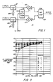
- FIG. 1 illustrates an exemplary embodiment of a local oscillator feed thru cancellation circuit in accordance with the present invention.
- the circuit 11 is used to actively cancel an LO feed thru signal by means of amplitude and phase balancing of the coupling network. As described below the unwanted LO feed thru signal and a coupled LO signal are actively matched in opposing amplitude and phase, and then combined in a coupler to cancel the LO feed thru signal.
- the circuit 11 consists of a power splitting coupler 13 for receiving and splitting an LO signal used to upconvert one or more IF signals.
- Figure 1 illustrates two IF input signals, IF input 1 and IF input 2.
- the IF input signals are communicated to mixers M1 and M2 where they are combined with the LO input signal to upconvert the IF signal.
- Bias regulation circuits 21 and 23 are disposed in the IF signal path to mixers M1 and M2.
- Bias regulation circuits 21 and 23 operate to selectively pass current from current sources 25 and 27 to mixers 15 and 17. By regulating the current to mixers 15 and 17 the amplitude and phase of the LO feed thru signal output from the mixers can be regulated.
- the outputs from mixers 15 and 17 are combined in 90 degree coupler 19, with the resulting signal output from coupler 19.
- mixers 15 and 17 may be formed as dual balanced mixers.
- One characteristic of such mixers is that they phase shift and attenuate the LO signal passing through the mixer, but not the IF signal.
- the bias regulation circuits 21 and 23 By selective adjustment of one or both of the bias regulation circuits 21 and 23 the proper canceling relationship can be obtained between the LO feed thru signal output from mixer 15 and the LO feed thru signal output from mixer 17.
- the desired canceling relationship is that two feed thru signals output from mixers 15 and 17 be of equal and opposite amplitude, and out of phase.
- Phase cancellation may be accomplished entirely by the mixers or may be partially accomplished by the mixers and partially by a phase shifting coupler (as illustrated at Figure 1).
- phase cancellation is effected by effecting a 90 degree phase difference in the outputs from mixers 15 and 17, and effecting an additional 90 degree phase difference through coupler 19.
- the 90 degree coupler 19 operates to phase shift one of the inputs to the coupler by 90 degrees. Accordingly, the desired phase regulation of mixers 15 and 17 is such as to obtain a 90 degree phase shift between LO feed thru signals output from the mixers. The remaining 90 degree phase shift is obtained by virtue of the operation of coupler 19.
- the invention is not limited to regulation of mixer circuits to provide a particular phase difference in respective outputs. Any phase difference in respective output signals may be useable to implement the present invention so long as the remaining circuitry operates to supplement the phase shift such that the two LO feed thru signals are canceling.
- the embodiment illustrated at Figure 1 contemplates the use of two IF input signals. However, it is to be understood that the circuit may operate with a single IF input signal, with the second IF input port terminated in a resistive load. Consequently, both single channel and multiple channel operation may be implemented through the use of the present invention. It is also to be understood that although the embodiment at Figure 1 illustrates two bias regulation circuits, a single bias regulation circuit may be used. However, the use of two bias regulation circuits has been found to be more effective in closely regulating the relative phase and amplitude of the signals output from the mixers.
- FIG. 2 illustrates an LO feed thru cancellation circuit 31, similar to that set forth at Figure 1, with additional circuitry .for automatically adjusting the operation of bias regulation circuits 21 and 23.
- the circuit 31 includes a coupler 33 interposed between the LO input source and the coupler 13.
- Circuit 31 also includes coupler 35 which receives a signal representative of the output from coupler 19, via coupler 37 and amplifier 41.
- Mixers 43 and 45 receive signals from couplers 35, and 55, and act as synchronous detectors to generate DC regulation signals via low pass filters 47, 49 and amplifiers 51 and 53.
- the DC regulation signals function to regulate the operation of bias control circuits 21, 23 by adjusting the bias signals communicated to the mixers to obtain LO phase and amplitude cancellation.
- the DC regulation signals are representative of the difference between the LO signal from coupler 33 and the LO signal from coupler 35. Consequently, the mixers 43 and 45 operate to generate signals used to regulate the operation of mixers 15 and 17 such that the LO feed thru signal is actively reduced.
- Figure 3 is a chart illustrating the LO feed thru cancellation that is to be expected using the present invention, from a given amplitude balance and phase match.
- the X axis represents the amplitude balance of the LO signal components output from mixers 15 and 17, and the different plots represents the accuracy of the canceling phase match obtained by the circuitry including mixers 15, 17 and coupler 19.
- the Y axis represents the level of LO feed thru cancellation that is obtainable given the amplitude balance and phase match.
- LO feed thru cancellation in the range of 60-100 dB is obtainable where the amplitude balance approaches 0 dB and the phase difference is 0 degrees.
- Approximately a 40 dB reduction of the LO feed thru signal amplitude occurs at a .5 degree phase imbalance, with approximately zero amplitude imbalance.
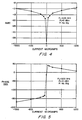
- Figure 4 is a graph showing the reduction in LO feed thru signal amplitude, or L to R port isolation, (in dBs) in relation to the injected bias current that occurs in a double-balanced mixer.
- Figure 5 is a graph showing the phase change of the LO feed thru signal (in degrees) in relation to the injected bias current that occurs in a double-balanced mixer.
- the measurements used to create Figures 4 and 5 were made with the frequency of the LO signal being 3 GHz.
- the power input to the mixer through the L port was approximately 0 dBm representing the lower limit of the usable drive for the mixer.
- No RF conversion signal was applied to the I port of the mixer.
- the I port was essentially open with current injected through an 18.2K resistor.
- Figures 4 and 5 demonstrate how injected bias current changes phase and amplitude of an LO signal applied to the mixer.
- the phase change generally measured approximately 207 degrees over a range of bias currents from -1 to +1 ma.
- the greatest phase slope appeared to occur close to zero injected bias current.
- the zero bias current also appeared to be in the operating region where the feed thru amplitude null occurs. Consequently, from the amplitude and phase versus frequency plots, the most widely varying amplitude and phase characteristics occurred close to zero injected bias.
- Variation in I port terminations; short, open and 50 ohm terminations cause some changes at lower frequencies, but did not significantly influence the responses above 2 GHz.
Landscapes
- Engineering & Computer Science (AREA)
- Power Engineering (AREA)
- Noise Elimination (AREA)
- Superheterodyne Receivers (AREA)
- Transmitters (AREA)
Applications Claiming Priority (2)
| Application Number | Priority Date | Filing Date | Title |
|---|---|---|---|
| US209241 | 1988-06-20 | ||
| US07/209,241 US5001773A (en) | 1988-06-20 | 1988-06-20 | Local oscillator feedthru cancellation circuit |
Publications (2)
| Publication Number | Publication Date |
|---|---|
| EP0347761A2 true EP0347761A2 (de) | 1989-12-27 |
| EP0347761A3 EP0347761A3 (de) | 1990-06-06 |
Family
ID=22777946
Family Applications (1)
| Application Number | Title | Priority Date | Filing Date |
|---|---|---|---|
| EP89110919A Ceased EP0347761A3 (de) | 1988-06-20 | 1989-06-16 | Schaltung und Verfahren zur Unterdrückung von durchgeführten Überlagerungsoszillator-Signalen |
Country Status (7)
| Country | Link |
|---|---|
| US (1) | US5001773A (de) |
| EP (1) | EP0347761A3 (de) |
| JP (1) | JPH0265429A (de) |
| KR (1) | KR930007286B1 (de) |
| AU (1) | AU602451B2 (de) |
| CA (1) | CA1333193C (de) |
| IL (1) | IL90125A (de) |
Cited By (8)
| Publication number | Priority date | Publication date | Assignee | Title |
|---|---|---|---|---|
| WO1991018445A1 (en) * | 1990-05-18 | 1991-11-28 | Northern Telecom Limited | Frequency converter for a radio communications system |
| FR2669787A1 (fr) * | 1990-11-23 | 1992-05-29 | Alcatel Telspace | Melangeur hyperfrequence symetrique. |
| FR2685577A1 (fr) * | 1991-12-23 | 1993-06-25 | Thomson Lgt | Procede et dispositif de transposition de frequence. |
| WO1996019863A1 (en) * | 1994-12-21 | 1996-06-27 | University Of Bristol | Image-reject mixers |
| EP0801465A1 (de) * | 1996-04-12 | 1997-10-15 | Continental Electronics Corporation | Funksendegerät |
| EP0973254A1 (de) * | 1998-07-15 | 2000-01-19 | Lucent Technologies Inc. | Schaltung zum Vermindern von einem Lecksignal aus einem lokalen Oszillator |
| WO2001071904A1 (en) * | 2000-03-21 | 2001-09-27 | Koninklijke Philips Electronics N.V. | Autocalibration of a transceiver through nulling of a dc-voltage in a receiver and injecting of dc-signals in a transmitter |
| EP1677417A4 (de) * | 2003-10-20 | 2008-05-21 | Matsushita Electric Industrial Co Ltd | Verstärkerschaltung |
Families Citing this family (10)
| Publication number | Priority date | Publication date | Assignee | Title |
|---|---|---|---|---|
| US5428837A (en) * | 1993-01-13 | 1995-06-27 | Anadigics, Inc. | Method and apparatus for reducing local oscillator leakage in integrated circuit receivers |
| US6970689B2 (en) * | 2002-02-15 | 2005-11-29 | Broadcom Corporation | Programmable mixer for reducing local oscillator feedthrough and radio applications thereof |
| US7613433B2 (en) * | 2003-12-19 | 2009-11-03 | Vixs Systems, Inc. | Reducing local oscillation leakage in a radio frequency transmitter |
| WO2006035509A1 (en) * | 2004-09-29 | 2006-04-06 | Nec Corporation | Error calculation circuit for mixer |
| US8706144B2 (en) | 2006-02-22 | 2014-04-22 | Qualcomm Incorporated | 1x and 1xEV-DO hybrid call setup |
| US7949323B1 (en) * | 2006-02-24 | 2011-05-24 | Texas Instruments Incorporated | Local oscillator leakage counterbalancing in a receiver |
| US8373594B1 (en) * | 2008-07-31 | 2013-02-12 | Lockheed Martin Corp | Low frequency directed energy shielding |
| EP2458729A1 (de) | 2010-11-30 | 2012-05-30 | Nxp B.V. | Gilbert-Mischer mit Entkopplung |
| US11177771B2 (en) | 2018-10-10 | 2021-11-16 | Analog Devices International Unlimited Company | Multi-core mixers with local oscillator leakage compensation |
| CN114650071B (zh) * | 2022-05-20 | 2022-08-16 | 深圳市鼎阳科技股份有限公司 | 一种用于矢量网络分析仪的本振馈通消除装置和方法 |
Family Cites Families (5)
| Publication number | Priority date | Publication date | Assignee | Title |
|---|---|---|---|---|
| JPS5679504A (en) * | 1979-12-03 | 1981-06-30 | Nec Corp | Frequency converter |
| EP0091201A1 (de) * | 1982-04-01 | 1983-10-12 | British Telecommunications | Mikrowellen-Diskriminator |
| DE3309399A1 (de) * | 1983-03-16 | 1984-09-20 | ANT Nachrichtentechnik GmbH, 7150 Backnang | Diodenmischer mit vorspannungssteuerung sowie dessen anwendung |
| US4584710A (en) * | 1984-11-13 | 1986-04-22 | The United States Of America As Represented By The Secretary Of The Navy | Coherent receiver phase and amplitude alignment circuit |
| IT1215323B (it) * | 1985-12-30 | 1990-01-31 | Gte Telecom Spa | Particolarmente per sistemi di convertitore armonico di frequenza ricetrasmissione ad alta frequenza. a banda laterale unica, |
-
1988
- 1988-06-20 US US07/209,241 patent/US5001773A/en not_active Expired - Fee Related
-
1989
- 1989-04-30 IL IL9012589A patent/IL90125A/en unknown
- 1989-05-01 CA CA000598311A patent/CA1333193C/en not_active Expired - Fee Related
- 1989-06-01 AU AU35902/89A patent/AU602451B2/en not_active Ceased
- 1989-06-16 EP EP89110919A patent/EP0347761A3/de not_active Ceased
- 1989-06-19 KR KR1019890008410A patent/KR930007286B1/ko not_active Expired - Fee Related
- 1989-06-20 JP JP1158124A patent/JPH0265429A/ja active Pending
Cited By (11)
| Publication number | Priority date | Publication date | Assignee | Title |
|---|---|---|---|---|
| WO1991018445A1 (en) * | 1990-05-18 | 1991-11-28 | Northern Telecom Limited | Frequency converter for a radio communications system |
| FR2669787A1 (fr) * | 1990-11-23 | 1992-05-29 | Alcatel Telspace | Melangeur hyperfrequence symetrique. |
| FR2685577A1 (fr) * | 1991-12-23 | 1993-06-25 | Thomson Lgt | Procede et dispositif de transposition de frequence. |
| EP0549411A1 (de) * | 1991-12-23 | 1993-06-30 | Thomcast | Verfahren und Anordnung zur Frequenzumsetzung |
| US5369794A (en) * | 1991-12-23 | 1994-11-29 | Thomson-Lgt Laboratoire General Des Telecommunications | Adaptive oscillator frequency feedthrough cancellation in mixer circuit |
| WO1996019863A1 (en) * | 1994-12-21 | 1996-06-27 | University Of Bristol | Image-reject mixers |
| US5950119A (en) * | 1994-12-21 | 1999-09-07 | University Of Bristol | Image-reject mixers |
| EP0801465A1 (de) * | 1996-04-12 | 1997-10-15 | Continental Electronics Corporation | Funksendegerät |
| EP0973254A1 (de) * | 1998-07-15 | 2000-01-19 | Lucent Technologies Inc. | Schaltung zum Vermindern von einem Lecksignal aus einem lokalen Oszillator |
| WO2001071904A1 (en) * | 2000-03-21 | 2001-09-27 | Koninklijke Philips Electronics N.V. | Autocalibration of a transceiver through nulling of a dc-voltage in a receiver and injecting of dc-signals in a transmitter |
| EP1677417A4 (de) * | 2003-10-20 | 2008-05-21 | Matsushita Electric Industrial Co Ltd | Verstärkerschaltung |
Also Published As
| Publication number | Publication date |
|---|---|
| AU3590289A (en) | 1989-12-21 |
| KR900001109A (ko) | 1990-01-31 |
| IL90125A0 (en) | 1989-12-15 |
| CA1333193C (en) | 1994-11-22 |
| KR930007286B1 (ko) | 1993-08-04 |
| JPH0265429A (ja) | 1990-03-06 |
| AU602451B2 (en) | 1990-10-11 |
| EP0347761A3 (de) | 1990-06-06 |
| IL90125A (en) | 1994-12-29 |
| US5001773A (en) | 1991-03-19 |
Similar Documents
| Publication | Publication Date | Title |
|---|---|---|
| US5001773A (en) | Local oscillator feedthru cancellation circuit | |
| US5140699A (en) | Detector DC offset compensator | |
| US5528196A (en) | Linear RF amplifier having reduced intermodulation distortion | |
| US4490684A (en) | Adaptive quadrature combining apparatus | |
| US4394624A (en) | Channelized feed-forward system | |
| US5323119A (en) | Amplifier having feed forward cancellation | |
| US7231191B2 (en) | Spurious ratio control circuit for use with feed-forward linear amplifiers | |
| US4090137A (en) | System for compensating cross-polarized waves to attenuate crosstalk | |
| US5222246A (en) | Parallel amplifiers with combining phase controlled from combiner difference port | |
| US5630223A (en) | Adaptive method and apparatus for eliminating interference between radio transceivers | |
| US4283795A (en) | Adaptive cross-polarization interference cancellation arrangements | |
| US5157346A (en) | Rf wideband high power amplifier | |
| US4317217A (en) | Tag generator for a same-frequency repeater | |
| US4544926A (en) | Adaptive jamming-signal canceler for radar receiver | |
| US5768699A (en) | Amplifier with detuned test signal cancellation for improved wide-band frequency response | |
| US4660042A (en) | Cancellation system for transmitter interference with nearby receiver | |
| EP0583306B1 (de) | Vorrichtung und verfahren zum justieren eines bandpassfilters, insbesondere eines kombinierfilters | |
| US4520476A (en) | Apparatus for enabling the duplex operation of a transmitter and receiver | |
| US6792250B1 (en) | Method and system for spurious and noise cancellation in a wireless transmitter | |
| US5926067A (en) | Sweep pilot technique for a control system that reduces distortion produced by electrical circuits | |
| US4028645A (en) | Automatic impedance matching using resistive and reactive diodes | |
| IE50880B1 (en) | Auto balancing duplexer for communication lines | |
| US4450417A (en) | Feed forward circuit | |
| GB2107540A (en) | Feedforward amplifiers | |
| GB1574778A (en) | Distortion compensation circuits |
Legal Events
| Date | Code | Title | Description |
|---|---|---|---|
| PUAI | Public reference made under article 153(3) epc to a published international application that has entered the european phase |
Free format text: ORIGINAL CODE: 0009012 |
|
| 17P | Request for examination filed |
Effective date: 19890711 |
|
| AK | Designated contracting states |
Kind code of ref document: A2 Designated state(s): CH DE ES FR GB IT LI NL SE |
|
| PUAL | Search report despatched |
Free format text: ORIGINAL CODE: 0009013 |
|
| AK | Designated contracting states |
Kind code of ref document: A3 Designated state(s): CH DE ES FR GB IT LI NL SE |
|
| 17Q | First examination report despatched |
Effective date: 19930507 |
|
| STAA | Information on the status of an ep patent application or granted ep patent |
Free format text: STATUS: THE APPLICATION HAS BEEN REFUSED |
|
| 18R | Application refused |
Effective date: 19950308 |