EP0347750A2 - Active hydraulically damping motor mounting - Google Patents
Active hydraulically damping motor mounting Download PDFInfo
- Publication number
- EP0347750A2 EP0347750A2 EP89110870A EP89110870A EP0347750A2 EP 0347750 A2 EP0347750 A2 EP 0347750A2 EP 89110870 A EP89110870 A EP 89110870A EP 89110870 A EP89110870 A EP 89110870A EP 0347750 A2 EP0347750 A2 EP 0347750A2
- Authority
- EP
- European Patent Office
- Prior art keywords
- engine mount
- mount according
- active
- active engine
- plate
- Prior art date
- Legal status (The legal status is an assumption and is not a legal conclusion. Google has not performed a legal analysis and makes no representation as to the accuracy of the status listed.)
- Granted
Links
Images
Classifications
-
- F—MECHANICAL ENGINEERING; LIGHTING; HEATING; WEAPONS; BLASTING
- F16—ENGINEERING ELEMENTS AND UNITS; GENERAL MEASURES FOR PRODUCING AND MAINTAINING EFFECTIVE FUNCTIONING OF MACHINES OR INSTALLATIONS; THERMAL INSULATION IN GENERAL
- F16F—SPRINGS; SHOCK-ABSORBERS; MEANS FOR DAMPING VIBRATION
- F16F13/00—Units comprising springs of the non-fluid type as well as vibration-dampers, shock-absorbers, or fluid springs
- F16F13/04—Units comprising springs of the non-fluid type as well as vibration-dampers, shock-absorbers, or fluid springs comprising both a plastics spring and a damper, e.g. a friction damper
- F16F13/06—Units comprising springs of the non-fluid type as well as vibration-dampers, shock-absorbers, or fluid springs comprising both a plastics spring and a damper, e.g. a friction damper the damper being a fluid damper, e.g. the plastics spring not forming a part of the wall of the fluid chamber of the damper
- F16F13/22—Units comprising springs of the non-fluid type as well as vibration-dampers, shock-absorbers, or fluid springs comprising both a plastics spring and a damper, e.g. a friction damper the damper being a fluid damper, e.g. the plastics spring not forming a part of the wall of the fluid chamber of the damper characterised by comprising also a dynamic damper
-
- F—MECHANICAL ENGINEERING; LIGHTING; HEATING; WEAPONS; BLASTING
- F16—ENGINEERING ELEMENTS AND UNITS; GENERAL MEASURES FOR PRODUCING AND MAINTAINING EFFECTIVE FUNCTIONING OF MACHINES OR INSTALLATIONS; THERMAL INSULATION IN GENERAL
- F16F—SPRINGS; SHOCK-ABSORBERS; MEANS FOR DAMPING VIBRATION
- F16F13/00—Units comprising springs of the non-fluid type as well as vibration-dampers, shock-absorbers, or fluid springs
- F16F13/04—Units comprising springs of the non-fluid type as well as vibration-dampers, shock-absorbers, or fluid springs comprising both a plastics spring and a damper, e.g. a friction damper
- F16F13/26—Units comprising springs of the non-fluid type as well as vibration-dampers, shock-absorbers, or fluid springs comprising both a plastics spring and a damper, e.g. a friction damper characterised by adjusting or regulating devices responsive to exterior conditions
- F16F13/30—Units comprising springs of the non-fluid type as well as vibration-dampers, shock-absorbers, or fluid springs comprising both a plastics spring and a damper, e.g. a friction damper characterised by adjusting or regulating devices responsive to exterior conditions comprising means for varying fluid viscosity, e.g. of magnetic or electrorheological fluids
Definitions
- the invention relates to an active, hydraulically damping motor bearing, which has a working chamber and a compensation chamber, which are at least partially surrounded by rubber-elastic peripheral walls and are separated from one another by a rigid intermediate plate with an overflow channel and at least partially contain electroviscous liquid as the working medium.
- Such an engine mount is known for example from DE-33 36 965 A1.
- the viscosity of the electroviscous fluid is changed by generating an electric field in the overflow channel between two plate-shaped electrodes in order to ensure a change in the damping in a rapid adaptation to the respective operating conditions.
- the present invention is based on the object, in a further development of this damping principle, to set the suspension and damping capacity of the engine mount even more optimally as a function of constantly changing driving conditions, and in particular to be able to tune high-frequency vibrations and thus the acoustic transmission behavior of the mount even better.
- the overflow channel in each case at its outlet openings to the working chamber and to the compensation chamber mer each with a rubber-elastic wall and filled with a low-viscosity liquid, and that in a central through hole of the intermediate plate, a circular disc-shaped, decoupling plate is overhung, the diameter of which is smaller than that of the hole to form an overflow gap, and that the walls delimiting the gap are designed as electrodes for applying a high voltage.
- a DC voltage source can be provided to generate the desired electric field.
- a voltage source which generates an AC voltage with a frequency greater than 0.1 Hz, the ignition coil of the motor vehicle being particularly suitable for this AC voltage source.
- the voltage applied to the electrodes can be changeable as a function of the engine speed.
- a conventional overflow channel 9 is initially arranged in the intermediate plate 5, which is only indicated schematically and can actually also be designed as a sufficiently long, helical channel.
- This overflow channel is closed on its outlet side to the working chamber 1 and on its outlet side to the compensation chamber 6, each with a rubber-elastic, preferably bellows-shaped wall 10 or 11.
- This channel 9 is filled with a low-viscosity liquid in order to be able to adjust the bearing as a high-frequency engine bearing.
- the intermediate plate 5 also has a central bore 12, in which a rigid decoupling plate 13 with the outer diameter d is free-swinging, that is, overhung. Between the wall of the bore 12 and the outer circumference of the decoupling plate 13, an annular gap 14 of width s and height h is thus formed, the assignment of which should satisfy the following conditions for a functional design: 10 ⁇ d s ⁇ 100 and 10 ⁇ h d ⁇ 200
- the walls of the gap 14 are now designed as electrodes for generating an electrical high-voltage field, specifically the inner wall of the bore 12 forms the electrode 17, which is at ground potential 18, while the outer circumference of the decoupling plate 13 as a high-voltage electrode 20 via a line 21 to a DC voltage source 22 or is connected to an AC voltage source 23.
- the AC voltage source 23 expediently generates a voltage with a frequency of greater than 0.1 Hz, for which the ignition coil of the motor vehicle, which is not shown in more detail, is preferably used.
- Working chamber 1 and compensation chamber 6 of the motor bearing are now filled with an electroviscous liquid, the viscosity of which can be increased significantly when flowing through the gap 14 by generating an appropriate electric field - until a liquid exchange is completely prevented.
- the axial free mobility of the decoupling plate 13 can be hindered by increasing the electrical field and thus changing the viscosity of the electroviscous liquid.
- the decoupling plate 13 can also be additionally coated with masses 25, so that their Til to strengthen the effect as a counter-oscillating spring-mass system.
- the spring stiffness of this system arises and is brought about by the stresses of the shear-stressed annular gap flow acting on the decoupling plate.
- the magnitude of the shear stress is influenced by the viscosity of the electroviscous liquid through the direct or alternating voltage field applied to the electrodes, which can be changed depending on the engine speed, for example, in order to achieve optimal isolation of acoustic vibrations in every driving condition.
- the decoupling plate 13 naturally also has corresponding guides and insulations, not shown in detail, in order to avoid rubbing against the counterelectrode and thus a short circuit of the system.
Abstract
Description
Die Erfindung bezieht sich auf ein aktives, hydraulisch dämpfendes Motorlager, das eine Arbeitskammer und eine Ausgleichskammer aufweist, die zumindest teilweise von gummielastischen Umfangswänden umgeben und durch eine starre Zwischenplatte mit einem Überströmkanal voneinander getrennt sind und zumindest teilweise elektroviskose Flüssigkeit als Arbeitsmedium enthalten.The invention relates to an active, hydraulically damping motor bearing, which has a working chamber and a compensation chamber, which are at least partially surrounded by rubber-elastic peripheral walls and are separated from one another by a rigid intermediate plate with an overflow channel and at least partially contain electroviscous liquid as the working medium.
Ein derartiges Motorlager ist beispielsweise aus der DE-33 36 965 A 1 bekannt. Dabei wird durch Erzeugen eines elektrischen Feldes im Überströmkanal zwischen zwei plattenförmigen Elektroden die Viskosität der elektroviskosen Flüssigkeit geändert, um damit eine Änderung der Dämpfung in schneller Anpassung an die jeweiligen Betriebszustände zu gewährleisten.Such an engine mount is known for example from DE-33 36 965 A1. The viscosity of the electroviscous fluid is changed by generating an electric field in the overflow channel between two plate-shaped electrodes in order to ensure a change in the damping in a rapid adaptation to the respective operating conditions.
Der vorliegenden Erfindung liegt demgegenüber die Aufgabe zugrunde, in Weiterbildung dieses Dämpfungsprinzips das Federungs- und Dämpfungsvermögen des Motorlagers in Abhängigkeit ständig wechselnder Fahrzustände noch optimaler einzustellen und insbesondere hochfrequente Schwingungen und damit das akustische Übertragungsverhalten des Lagers noch besser abstimmen zu können.In contrast, the present invention is based on the object, in a further development of this damping principle, to set the suspension and damping capacity of the engine mount even more optimally as a function of constantly changing driving conditions, and in particular to be able to tune high-frequency vibrations and thus the acoustic transmission behavior of the mount even better.
Zur Lösung dieser Aufgabe ist daher erfindungsgemäß vorgesehen, daß der Überströmkanal jeweils an seinen Austrittsöffnungen zur Arbeitskammer und zur Ausgleichskam mer mit je einer gummielastischen Wandung abgeschlossen und mit einer niederviskosen Flüssigkeit gefüllt ist, und daß in einer zentralen Durchgangsbohrung der Zwischenplatte eine kreisscheibenförmige, massive Entkopplungsplatte fliegend gelagert ist, deren Durchmesser kleiner als der der Bohrung ist, um einen Überströmspalt zu bilden, und daß die den Spalt begrenzenden Wandungen als Elektroden zum Anlegen einer Hochspannung ausgebildet sind.To solve this problem it is therefore provided according to the invention that the overflow channel in each case at its outlet openings to the working chamber and to the compensation chamber mer each with a rubber-elastic wall and filled with a low-viscosity liquid, and that in a central through hole of the intermediate plate, a circular disc-shaped, decoupling plate is overhung, the diameter of which is smaller than that of the hole to form an overflow gap, and that the walls delimiting the gap are designed as electrodes for applying a high voltage.
Da in herkömmlichen Überströmkanälen hinreichend großer Länge ein tatsächlicher Flüssigkeitsaustausch nur in einem sehr begrenzten Maße stattfindet und stattdessen die in dem Überströmkanal enthaltene Flüssigkeitsmenge lediglich zu einer viskositätsabhängig reibungsbehafteten Schwingung und damit zu einer Wirkung als Tilgermasse angeregt wird, ist es auch möglich, die Flüssigkeitsmenge dieses Kanals so von den übrigen Flüssigkeitsräumen abzutrennen, daß dennoch Schwingungen dieser Flüssigkeitssäule nicht behindert werden, daß aber andererseits mit einem Medium anderer, insbesonderer niedrigerer Viskosität als der des Hauptmediums im Lager eine Abstimmung auf ganz spezielle Frequenzen erreicht werden kann. Durch die Ausbildung des eigentlichen Überströmspaltes an der Randfläche einer schwingenden Masse und Beeinflussung der Viskosität der diesen Spalt durchströmenden Flüssigkeit ist damit die Federsteifigkeit dieses Schwingungssystems beeinflußbar, um in jedem Fahrzustand eine optimale Isolation akustischer Schwingungen zu erreichen.Since in conventional overflow channels of sufficient length, an actual liquid exchange takes place only to a very limited extent and instead the amount of liquid contained in the overflow channel is only stimulated to a vibration-dependent vibration and thus to act as an absorber mass, it is also possible to determine the amount of liquid in this channel to be separated from the other liquid spaces in such a way that vibrations of this liquid column are not hindered, but on the other hand, with a medium of a different, in particular lower viscosity than that of the main medium in the bearing, tuning to very specific frequencies can be achieved. By forming the actual overflow gap on the edge surface of a vibrating mass and influencing the viscosity of the liquid flowing through this gap, the spring stiffness of this vibration system can be influenced in order to achieve optimal isolation of acoustic vibrations in every driving state.
Zweckmäßig ist es dabei, wenn die Bohrungswandung, die auf Erdpotential liegende Elektrode und der Außenumfang der Entkopplungsplatte die an die Spannungsquelle angeschlossene Elektrode bilden.It is expedient if the bore wall, the electrode lying at ground potential and the outer circumference of the decoupling plate form the electrode connected to the voltage source.
Zur Erzeugung des gewünschten elektrischen Feldes kann dabei eine Gleichspannungsquelle vorgesehen sein.A DC voltage source can be provided to generate the desired electric field.
Von besonderem Vorteil ist es aber, wenn eine eine Wechselspannung mit einer Frequenz größer als 0,1 Hz erzeugende Spannungsquelle vorgesehen ist, wobei sich für diese Wechselspannungsquelle insbesondere die Zündspule des Kraftfahrzeugs eignet. Dabei kann die an den Elektroden anliegende Spannung in Abhängigkeit von der Motordrehzahl änderbar sein.However, it is particularly advantageous if a voltage source is provided which generates an AC voltage with a frequency greater than 0.1 Hz, the ignition coil of the motor vehicle being particularly suitable for this AC voltage source. The voltage applied to the electrodes can be changeable as a function of the engine speed.
Zweckmäßigerweise ist die Entkopplungsplatte auf Oberund Unterseite mittels eines Käfigs zur axialen Wegbegrenzung am Herausfallen gesichert. Dabei können auf der Entkopplungsplatte zusätzliche Massen angeordnet sein, um ihre Tilgerwirkung zu verstärken.The decoupling plate is expediently secured on the top and bottom sides by means of a cage for axially limiting the distance from falling out. In this case, additional masses can be arranged on the decoupling plate in order to increase their absorber effect.
Für eine optimale Auslegung des Lagers sollte das Verhältnis von Durchmesser d der Entkopplungsplatte zu Breite s des Überströmspaltes zwischen 10 und 100 liegen, so wie das Verhältnis von Durchmesser d der Entkopplungsplatte zu Höhe h des Überströmspaltes zwischen 10 und 200.For an optimal design of the bearing, the ratio of diameter d of the decoupling plate to width s of the overflow gap should be between 10 and 100, as well as the ratio of diameter d of the decoupling plate to height h of the overflow gap between 10 and 200.
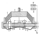
Anhand einer schematischen Zeichnung sind Aufbau und Funktionsweise eines Motorlagers nach der Erfindung näher erläutert. Dabei zeigt die einzige Figur einen Längsschnitt durch ein derartiges Lager mit den entsprechenden Hochspannungsanschlüssen.The structure and mode of operation of an engine mount according to the invention are explained in more detail using a schematic drawing. The single figure shows a longitudinal section through such a bearing with the corresponding high-voltage connections.
Wie aus der Zeichnung zu ersehen ist, weist das Motorlager in herkömmlicher Weise eine Arbeitskammer 1 auf, die durch eine gummielastische Wandung 2 an die die Lagerplatte 3 mit dem Haltebolzen 4 zur Aufnahme des nicht näher dargestellten Motors anvulkanisiert und durch die starre Zwischenplatte 5 begrenzt ist. Auf der anderen Seite der Zwischenplatte befindet sich die Ausgleichskammer 6, die von einer weiteren gummielastischen, sehr volumennachgiebigen Wandung 7 berandet wird.As can be seen from the drawing, the engine mount has in a conventional manner a working
In der Zwischenplatte 5 ist zunächst ein herkömmlicher Überströmkanal 9 angeordet, der nur schematisch angedeutet ist und tatsächlich auch als hinreichend langer, wendelförmiger Kanal ausgebildet sein kann. Dieser Überströmkanal ist auf seiner Austrittsseite zur Arbeitskammer 1 und auf seiner Austrittsseite zur Ausgleichskammer 6 mit je einer gummielastischen, vorzugsweise faltenbalgförmigen Wandung 10 bzw. 11 abgeschlossen. Dieser Kanal 9 ist mit einer niedrigviskosen Flüssigkeit gefüllt, um das Lager als hochfrequent abgestimmt arbeitendes Motorlager einstellen zu können. Dies wird durch die Verwendung einer niederviskosen Flüssigkeit erreicht, die bei in die Arbeitskammer 1 eingeleiteten Schwingungen und deren praktisch ungedämpften Weitergabe über die faltenbalgförmige Wandung 10 an die Flüssigkeit zu Schwingungen mit relativ geringer Reibungsdämpfung angeregt wird und damit als eine auf ein bestimmtes Frequenzspektrum abgestimmte Tilgermasse wirkt.A conventional overflow channel 9 is initially arranged in the
Die Zwischenplatte 5 weist darüber hinaus eine zentrale Bohrung 12 auf, in der eine starre Entkopplungsplatte 13 mit dem Außendurchmesser d freischwingend, d.h. fliegend gelagert ist. Zwischen der Wandung der Bohrung 12 und dem Außenumfang der Entkopplungsplatte 13 wird somit ein Ringspalt 14 von der Breite s und der Höhe h gebildet, deren Zuordnung für eine funktionsgerechte Auslegung folgenden Bedingungen genügen sollte:
10 ≦ ![]()
10 ≦ ![]()
Um dabei ein Herausfallen der Entkopplungsplatte 13 aus der Bohrung 12 zu verhindern, ist diese durch einen Käfig bzw. 16 auf Ober- und Unterseite der Zwischenplatte 5 gesichert.In order to prevent the
Die Wandungen des Spaltes 14 sind nunmehr als Elektroden zum Erzeugen eines elektrischen Hochspanungsfeldes ausgebildet und zwar bildet die Innenwandung der Bohrung 12 die Elektrode 17, die auf Erdpotential 18 liegt, während der Außenumfang der Entkopplungsplatte 13 als Hochspannungselektrode 20 über eine Leitung 21 an eine Gleichspannungsquelle 22 oder aber an eine Wechselspannungsquelle 23 angeschlossen ist. Die Wechselspannungsquelle 23 erzeugt dabei zweckmäßigerweise eine Spannung mit einer Frequenz von größer als 0,1 Hz, wofür vorzugsweise die nicht näher dargestellte Zündspule des Kraftfahrzeuges verwendet wird.The walls of the
Arbeitskammer 1 und Ausgleichskammer 6 des Motorlagers sind nunmehr mit einer elektroviskosen Flüssigkeit gefüllt, deren Viskosität beim Durchströmen durch den Spalt 14 durch Erzeugen eines entsprechenden elektrischen Feldes wesentlich erhöht werden kann - bis zum vollständigen Unterbinden eines Flüssigkeitsaustausches.
Wird nun die Entkopplungsplatte 13 durch in der Arbeitskammer 1 wechselnde Druckkräfte zu Schwingungen angeregt und der Ringspalt 14 oszillatorisch und unter Scherbeanspruchung durchströmt, kann die axiale freie Beweglichkeit der Entkopplungsplatte 13 durch Verstärken des elektrischen Feldes und damit Änderung der Zähigkeit der elektroviskosen Flüssigkeit behindert werden.If the
Die Entkopplungsplatte 13 kann darüber hinaus noch zusätzlich mit Massen 25 belegt werden, um damit ihre Til gerwirkung als gegenschwingendes Feder-Masse-System zu verstärken. Die Federsteifigkeit dieses Systems entsteht und wird bewirkt durch die an der Entkopplungsplatte angreifenden Spannungen der scherbeanspruchten Ringspaltströmung. Der Betrag der Schubspannung wird über die Viskosität der elektroviskosen Flüssigkeit durch das an den Elektroden anliegende Gleich- oder Wechselspannungsfeld beeinflußt, das beispielsweise in Abhängigkeit von der Motordrehzahl verändert werden kann, um somit in jedem Fahrzustand eine optimale Isolation akustischer Schwingungen zu erreichen.The
Die Entkopplungsplatte 13 weist selbstverständlich noch entsprechende, nicht näher dargestellte Führungen und Isolationen auf, um ein Anstreifen an der Gegenelektrode und damit einen Kurzschluß des Systems zu vermeiden.The
Insgesamt ergibt sich also ein Motorlager, bei dem durch Verwendung einer niederviskosen Flüssigkeit die Flüssigkeitssäule im Überströmkanal bei Schwingungsanregung phasenverschoben zur Anregung schwingt, wodurch hohe Dämpfung im niederfrequenten Bereich mit Verlustwinkelmaxima zwischen 6 und 12 Hz und Reynoldszahlen sehr viel größer 1 erreicht werden, da bei diesen Flüssigkeiten der Trägheitseffekt der Flüssigkeitssäule ohne hohen Reibungsanteil überwiegt und damit sich eine hohe Eigenfrequenz der schwingenden Flüssigkeitsmenge ergibt.Overall, this results in an engine mount in which the use of a low-viscosity liquid causes the liquid column in the overflow channel to vibrate out of phase with excitation when vibrating, which means that high damping in the low-frequency range with loss angle maxima between 6 and 12 Hz and Reynolds numbers are achieved much greater than 1, since these Liquids outweigh the inertia effect of the liquid column without a high proportion of friction, resulting in a high natural frequency of the oscillating amount of liquid.
Damit wird also im wesentlichen verhindert, daß sich Motorstuckern auf die Fahrgastzelle überträgt. Gleichzeitig wird die Entkopplungsplatte durch Anlegen des Hochspannungsfeldes festgehalten. Bei kleineren Anregungsamplituden wird dagegen das Lager "weich" geschaltet, wobei sich die Entkopplungsplatte unter dem Einfluß des stufenlos verstellbaren Spannungsfeldes bewegen kann, um damit eine Isolation akustischer Schwingungen in unmittelbarer Anpassung an den jeweiligen Betriebszustand und die Frequenz der Störquelle zu erreichen.This essentially prevents engine stucking from being transmitted to the passenger compartment. At the same time, the decoupling plate is held in place by applying the high-voltage field. In the case of smaller excitation amplitudes, on the other hand, the bearing is switched to "soft", the decoupling plate being able to move under the influence of the infinitely variable voltage field in order to achieve a Isolation of acoustic vibrations in direct adaptation to the respective operating state and the frequency of the interference source.
Claims (11)
Applications Claiming Priority (2)
| Application Number | Priority Date | Filing Date | Title |
|---|---|---|---|
| DE3820818 | 1988-06-20 | ||
| DE3820818A DE3820818C1 (en) | 1988-06-20 | 1988-06-20 |
Publications (3)
| Publication Number | Publication Date |
|---|---|
| EP0347750A2 true EP0347750A2 (en) | 1989-12-27 |
| EP0347750A3 EP0347750A3 (en) | 1990-02-07 |
| EP0347750B1 EP0347750B1 (en) | 1992-05-27 |
Family
ID=6356860
Family Applications (1)
| Application Number | Title | Priority Date | Filing Date |
|---|---|---|---|
| EP89110870A Expired - Lifetime EP0347750B1 (en) | 1988-06-20 | 1989-06-15 | Active hydraulically damping motor mounting |
Country Status (2)
| Country | Link |
|---|---|
| EP (1) | EP0347750B1 (en) |
| DE (2) | DE3820818C1 (en) |
Families Citing this family (2)
| Publication number | Priority date | Publication date | Assignee | Title |
|---|---|---|---|---|
| DE3933248C2 (en) * | 1989-10-05 | 1994-02-24 | Continental Ag | Hydraulically damping displacement bearing with switchable free travel device |
| DE4126674C2 (en) * | 1991-08-13 | 1994-10-13 | Freudenberg Carl Fa | Hydraulically damping rubber bearing |
Citations (5)
| Publication number | Priority date | Publication date | Assignee | Title |
|---|---|---|---|---|
| DE3336965A1 (en) * | 1983-10-11 | 1985-05-02 | Metzeler Kautschuk GmbH, 8000 München | TWO-CHAMBER ENGINE MOUNT WITH HYDRAULIC DAMPING |
| DE3506047A1 (en) * | 1984-02-21 | 1985-08-29 | Honda Giken Kogyo K.K., Tokio/Tokyo | VIBRATION INSULATOR |
| JPS60175834A (en) * | 1984-02-21 | 1985-09-10 | Honda Motor Co Ltd | Mount filled with fluid |
| EP0209883A2 (en) * | 1985-07-25 | 1987-01-28 | Metzeler Gimetall Ag | Hydraulically damped engine mount having two chambers |
| DE3731024A1 (en) * | 1986-09-16 | 1988-03-24 | Bridgestone Corp | VIBRATION DAMPING DEVICE |
Family Cites Families (2)
| Publication number | Priority date | Publication date | Assignee | Title |
|---|---|---|---|---|
| JPS61140635A (en) * | 1984-12-13 | 1986-06-27 | Kinugawa Rubber Ind Co Ltd | Valve device for liquid filled type insulator |
| DE3525673A1 (en) * | 1985-07-18 | 1987-01-22 | Metzeler Kautschuk | ACTIVE TWO-CHAMBER ENGINE MOUNT WITH HYDRAULIC DAMPING |
-
1988
- 1988-06-20 DE DE3820818A patent/DE3820818C1/de not_active Expired
-
1989
- 1989-06-15 EP EP89110870A patent/EP0347750B1/en not_active Expired - Lifetime
- 1989-06-15 DE DE8989110870T patent/DE58901524D1/en not_active Expired - Fee Related
Patent Citations (5)
| Publication number | Priority date | Publication date | Assignee | Title |
|---|---|---|---|---|
| DE3336965A1 (en) * | 1983-10-11 | 1985-05-02 | Metzeler Kautschuk GmbH, 8000 München | TWO-CHAMBER ENGINE MOUNT WITH HYDRAULIC DAMPING |
| DE3506047A1 (en) * | 1984-02-21 | 1985-08-29 | Honda Giken Kogyo K.K., Tokio/Tokyo | VIBRATION INSULATOR |
| JPS60175834A (en) * | 1984-02-21 | 1985-09-10 | Honda Motor Co Ltd | Mount filled with fluid |
| EP0209883A2 (en) * | 1985-07-25 | 1987-01-28 | Metzeler Gimetall Ag | Hydraulically damped engine mount having two chambers |
| DE3731024A1 (en) * | 1986-09-16 | 1988-03-24 | Bridgestone Corp | VIBRATION DAMPING DEVICE |
Non-Patent Citations (1)
| Title |
|---|
| PATENT ABSTRACTS OF JAPAN, Band 10, Nr. 14 (M-447)[2071], 21. Januar 1986; & JP-A-60 175 834 (HONDA GIKEN KOGYO K.K.) 10-09-1985 * |
Also Published As
| Publication number | Publication date |
|---|---|
| EP0347750B1 (en) | 1992-05-27 |
| DE58901524D1 (en) | 1992-07-02 |
| DE3820818C1 (en) | 1989-10-05 |
| EP0347750A3 (en) | 1990-02-07 |
Similar Documents
| Publication | Publication Date | Title |
|---|---|---|
| EP0137112B2 (en) | Two space hydraulic damping support | |
| EP0218202B1 (en) | Active twin chamber engine mounting | |
| EP0975892B1 (en) | Spring/mass vibratory force coupler | |
| DE60224900T2 (en) | Hydraulic bearing with magnetorheological fluid | |
| EP0044545B1 (en) | Engine mounting with two hydraulic damping chambers | |
| DE3006778C2 (en) | ||
| EP0460278B1 (en) | Rubber mount and a piston engine | |
| DE3920891A1 (en) | FLUID-FILLED, ELASTOMERIC DAMPING DEVICE | |
| EP0110197B1 (en) | Engine mounting with two hydraulic damping chambers | |
| EP0164081A2 (en) | Double chamber hydraulic motor damping support | |
| DE3402715A1 (en) | TWO-CHAMBER ENGINE MOUNT WITH HYDRAULIC DAMPING | |
| EP0421052B1 (en) | Hydraulically-damped rubber bushing | |
| EP0235540A2 (en) | Hydraulic-damping mounting | |
| DE102006000320A1 (en) | Fluid-filled engine mount | |
| DE3509000A1 (en) | Fixing device for engines | |
| DE3617813C2 (en) | ||
| DE3932064A1 (en) | SUSPENSION DEVICE FOR MOTOR VEHICLE MACHINES | |
| EP0347750B1 (en) | Active hydraulically damping motor mounting | |
| DE3712656C2 (en) | ||
| DE10117661A1 (en) | Hydraulic two-chamber bearing for damping vibrations | |
| DE3738716C2 (en) | ||
| EP0271848A2 (en) | Active hydraulically damping motor mount | |
| DE3617812A1 (en) | ENGINE MOUNT | |
| EP0607897A2 (en) | Hydraulically-damped, active engine support | |
| EP0189509B1 (en) | Engine mount |
Legal Events
| Date | Code | Title | Description |
|---|---|---|---|
| PUAI | Public reference made under article 153(3) epc to a published international application that has entered the european phase |
Free format text: ORIGINAL CODE: 0009012 |
|
| PUAL | Search report despatched |
Free format text: ORIGINAL CODE: 0009013 |
|
| 17P | Request for examination filed |
Effective date: 19890615 |
|
| AK | Designated contracting states |
Kind code of ref document: A2 Designated state(s): DE GB IT |
|
| AK | Designated contracting states |
Kind code of ref document: A3 Designated state(s): DE GB IT |
|
| RAP1 | Party data changed (applicant data changed or rights of an application transferred) |
Owner name: METZELER GIMETALL AG |
|
| 17Q | First examination report despatched |
Effective date: 19911119 |
|
| GRAA | (expected) grant |
Free format text: ORIGINAL CODE: 0009210 |
|
| AK | Designated contracting states |
Kind code of ref document: B1 Designated state(s): DE GB IT |
|
| GBT | Gb: translation of ep patent filed (gb section 77(6)(a)/1977) | ||
| REF | Corresponds to: |
Ref document number: 58901524 Country of ref document: DE Date of ref document: 19920702 |
|
| ITF | It: translation for a ep patent filed |
Owner name: ING. C. GREGORJ S.P.A. |
|
| PGFP | Annual fee paid to national office [announced via postgrant information from national office to epo] |
Ref country code: DE Payment date: 19920709 Year of fee payment: 4 |
|
| PLBE | No opposition filed within time limit |
Free format text: ORIGINAL CODE: 0009261 |
|
| STAA | Information on the status of an ep patent application or granted ep patent |
Free format text: STATUS: NO OPPOSITION FILED WITHIN TIME LIMIT |
|
| 26N | No opposition filed | ||
| PG25 | Lapsed in a contracting state [announced via postgrant information from national office to epo] |
Ref country code: GB Effective date: 19930615 |
|
| GBPC | Gb: european patent ceased through non-payment of renewal fee |
Effective date: 19930615 |
|
| PG25 | Lapsed in a contracting state [announced via postgrant information from national office to epo] |
Ref country code: DE Effective date: 19940301 |
|
| PG25 | Lapsed in a contracting state [announced via postgrant information from national office to epo] |
Ref country code: IT Free format text: LAPSE BECAUSE OF NON-PAYMENT OF DUE FEES;WARNING: LAPSES OF ITALIAN PATENTS WITH EFFECTIVE DATE BEFORE 2007 MAY HAVE OCCURRED AT ANY TIME BEFORE 2007. THE CORRECT EFFECTIVE DATE MAY BE DIFFERENT FROM THE ONE RECORDED. Effective date: 20050615 |