EP0347055A2 - On-line rheological measurements - Google Patents
On-line rheological measurements Download PDFInfo
- Publication number
- EP0347055A2 EP0347055A2 EP89305324A EP89305324A EP0347055A2 EP 0347055 A2 EP0347055 A2 EP 0347055A2 EP 89305324 A EP89305324 A EP 89305324A EP 89305324 A EP89305324 A EP 89305324A EP 0347055 A2 EP0347055 A2 EP 0347055A2
- Authority
- EP
- European Patent Office
- Prior art keywords
- capillary passage
- exit
- melt
- metering pump
- diverted
- Prior art date
- Legal status (The legal status is an assumption and is not a legal conclusion. Google has not performed a legal analysis and makes no representation as to the accuracy of the status listed.)
- Granted
Links
Images


Classifications
-
- G—PHYSICS
- G01—MEASURING; TESTING
- G01N—INVESTIGATING OR ANALYSING MATERIALS BY DETERMINING THEIR CHEMICAL OR PHYSICAL PROPERTIES
- G01N11/00—Investigating flow properties of materials, e.g. viscosity, plasticity; Analysing materials by determining flow properties
- G01N11/02—Investigating flow properties of materials, e.g. viscosity, plasticity; Analysing materials by determining flow properties by measuring flow of the material
- G01N11/04—Investigating flow properties of materials, e.g. viscosity, plasticity; Analysing materials by determining flow properties by measuring flow of the material through a restricted passage, e.g. tube, aperture
- G01N11/08—Investigating flow properties of materials, e.g. viscosity, plasticity; Analysing materials by determining flow properties by measuring flow of the material through a restricted passage, e.g. tube, aperture by measuring pressure required to produce a known flow
-
- G—PHYSICS
- G01—MEASURING; TESTING
- G01N—INVESTIGATING OR ANALYSING MATERIALS BY DETERMINING THEIR CHEMICAL OR PHYSICAL PROPERTIES
- G01N33/00—Investigating or analysing materials by specific methods not covered by groups G01N1/00 - G01N31/00
- G01N33/44—Resins; Plastics; Rubber; Leather
- G01N33/442—Resins; Plastics
Definitions
- the present invention relates generally to the measurement of rheological characteristics of melted materials and pertains, more specifically, to the on-line measurement of such characteristics as the viscosity of polymer melts for purposes of control of manufacturing processes involving molten plastics.
- Rheological testing equipment has been available for a very long time in conducting laboratory measurements of certain important characteristics of polymer melts used in various manufacturing processes. Thus, such properties as viscosity and melt flow index are being measured in the laboratory with increasing accuracy. More recently, efforts have been directed toward the measurement of these characteristics on-line, during the manufacturing process itself, in order to provide constant, closer control over the quality of the melt utilized in the process. On-line measurement requires equipment which not only is relatively easy to use and maintain, but which is rugged enough to withstand the operating conditions to which the equipment will be exposed. In order to be effective, the equipment must be responsive, and must avoid disturbing the manufacturing process being monitored.
- rheometers which divert a portion of the polymer melt from the main stream of molten plastic, conduct measurements on the diverted melt, and then discard the diverted melt. Discarding of the diverted melt is wasteful and proper disposal of the discarded melt often presents a problem which must be dealt with in the manufacturing plant. More recently, rheometers have been developed in which the diverted melt is returned to the main stream, thereby eliminating waste and disposal problems. These rheometers usually employ a first metering pump, such as a gear pump, to feed a capillary passage with a controlled flow of diverted melt, and a second metering pump to return the diverted melt to the main stream.
- a first metering pump such as a gear pump
- the present invention constitutes an improvement in on-line capillary rheometers and in the techniques which utilize apparatus of the type in which melt is diverted to a rheometer and the diverted melt is returned to the main stream and extends the capability of such on-line rheometers to enable effective use in connection with the control of processes where measurements must be conducted quickly and response time must be held to a minimum, such as processes in which polymers are blended, alloyed or reacted.
- the present invention has several objectives and provides a number of advantages, some of which are summarized as follows: Enables truly on-line measurements for attaining quicker response and more accurate control of manufacturing processes involving polymer melts; allows on-line measurements without the necessity for controlling the temperature of the diverted polymer melt, thereby enabling measurements to be made in close proximity to the main stream of polymer melt for decreased residence time, increased accuracy and quicker response; permits the conduct of on-line measurements with a minimal intrusion into the process being monitored; permits increased versatility in the nature and extent of the information derived from on-line measurements of polymer melts, as well as increased accuracy in the information itself; enables ease of installation and use in connection with current manufacturing equipment and techniques; allows ready adaptation for use in connection with a wide variety of materials and operating conditions; provides a convenient station for additional sensing and observation devices available for monitoring the quality of the polymer melt; facilitates cleaning and general maintenance, as well as replacement of component parts either for repair or adaptation to specific materials and operating conditions; and provides a simple and rugged construction for economical manufacture and reliable long-
- the present invention which may be described briefly as an improvement whereby on-line rheological measurements are made in a process melt so as to provide process control information based upon the viscosity of the process melt, utilizing a rheometer of the type in which a first metering pump delivers diverted melt from a process main stream to the entrance of a capillary passage and a second metering pump returns the diverted melt from the exit of the capillary passage to the process main stream and the diverted melt is subjected to a pressure drop between spaced apart locations along the capillary passage between the entrance and the exit, by measuring the viscosity of the diverted melt by controlling the rate of flow of the melt through the capillary passage to maintain essentially constant the pressure drop in the diverted melt between the spaced apart locations and measuring the actual temperature of the diverted melt in the capillary passage so as to provide the process control information based upon the measured viscosity of the diverted melt corrected to a known
- the speed of the second metering pump may be controlled independent of the speed of the first metering pump so as to maintain the pressure at the exit essentially constant while the diverted melt is subjected to the pressure drop in the capillary passage.
- the capillary passage is placed in close proximity to the process main stream by a mounting plate which includes a relatively short first conduit between the process main stream and the entrance to the capillary passage, and a relatively short second conduit between the exit of the capillary passage and the process main stream for maintaining a relatively short residence time during which the diverted melt resides outside the process main stream so as to attain a relatively quick response to changes in the measured viscosity.
- the rheometer includes a first block, a second block juxtaposed with the first block, and a relatively thin plate interposed between the first block and the second block, the plate including a slot providing a chamber between the first and second blocks, the chamber extending along a direction from the entrance toward the exit for providing the capillary passage between the entrance and the exit.
- Extruder 10 is in use, generating melted polymer for the continuous manufacture of items constructed of plastic material.
- a control system is utilized in connection with the operation of the extruder to monitor certain characteristics of the polymer melt and to operate the extruder in the manner necessary to attain the desired quality in the extrudate.
- An on-line rheometer 20, constructed in accordance with the present invention, is a part of that control system.
- a portion of the polymer melt in the extruder 10 is diverted from the main stream in the extruder to the rheometer 20 through an inlet conduit 22 and is advanced by a first metering pump 24 through an entrance conduit 26 to the entrance 28 to a capillary passage 30 of selected configuration and dimensions.
- the diverted polymer melt traverses the capillary passage 30 and then leaves the capillary passage 30 via an exit conduit 32.
- a second metering pump 34 advances the diverted polymer melt through an outlet conduit 36 which communicates with the extruder 10 so that the diverted polymer melt is returned to the main stream of polymer melt in the extruder 10.
- a first pressure-responsive transducer 40 is placed at a location adjacent the entrance 28 and provides information indicative of the pressure P1 in the polymer melt at that location in the capillary passage 30.
- a second pressure-responsive transducer 42 is placed at a second location spaced downstream from the first location and provides information indicative of the pressure P2 at the second location in the capillary passage 30.
- the rate of flow of the polymer melt in the capillary passage 30 is governed by the speed of the first metering pump 24 and that speed is determined by the speed of the motor 44 which drives the metering pump 24.
- the speed of motor 44 is controlled by a controller 46 which itself is connected to a computer 50.
- Temperature sensors 52 and 54 provide information to computer 50 indicative of the temperature (T1 and T2) of the polymer melt adjacent each of the locations of the pressure-responsive transducers 40 and 42.
- viscosity is calculated from the measured pressure drop (P1 - P2) along the capillary passage 30 and the rate of flow of the polymer melt in the capillary passage 30, while the temperature of the polymer melt is maintained at a constant value.
- temperature sensors corresponding to temperature sensors 52 and 54, would be used to provide temperature information to operate a heating or cooling arrangement which would maintain the desired constant temperature in the polymer melt being subjected to stress in a capillary passage corresponding to capillary passage 30, the measure of the stress then being available in terms of the pressure drop (corresponding to P1 - P2) indicated by the pressure-responsive transducers similar to pressure-responsive transducers 40 and 42.
- the present invention reduces residence time and decreases response time, thereby enabling more truly on-line operation, by eliminating the requirement for control of the temperature of the diverted polymer melt, allowing rheometer 20 to be placed in close proximity to extruder 10, or other process apparatus, for a reduction in residence time, during which the diverted polymer melt is outside the main stream, and a concomitant reduction in response time in the control system.
- the pressure drop P1 - P2 is maintained constant by controlling the speed of both the first and the second metering pumps 24 and 34.
- the speed of the first metering pump 24 then provides a measure of the rate of flow of the polymer melt traversing the capillary passage 30, which rate of flow is an indication of the viscosity of the polymer melt.
- the viscosity is determined with a high degree of accuracy. Since the temperature dependence of polymer materials at constant stress is well known, the maintenance of a constant stress on the polymer melt in the capillary passage 30, that is, the maintenance of a constant pressure drop P1 - P2, enables the temperature information, as determined by T1 and T2 (preferably by averaging T1 and T2), to be utilized to relate the measurements to a known standard so that it is not necessary to control the temperature of the diverted polymer melt, but merely to measure the temperature and then correct the measured viscosity information, in accordance with the measured temperature, to derive the desired control information.
- the pressure drop (P1 - P2) is solely a result of the traverse of the capillary passage 30 by the polymer melt, and that the measured pressures are not affected by any irregularities in the operation of the various components of the rheometer 20.
- the metering pumps usually are driven by a common motor and drive and the accuracy of the mechanical components is relied upon to maintain the same flow rate through both metering pumps so that the measured pressures within the capillary passage are unaffected by any variation in flow rate between the two metering pumps.
- rheometer 20 includes means for driving the second metering pump 34 independent of the first metering pump 24, the means being illustrated in the form of a second motor 60 controlled by a second controller 62 connected to computer 50.
- a third pressure-responsive transducer 64 is located adjacent exit 66 from the capillary passage 30 and provides information indicative of the pressure P3 at the exit.
- the information provided by the third pressure-responsive transducer 64 is utilized by the computer 50 to operate the controller 62 so that the motor 60 actuates the second metering pump 34 at the speed necessary to maintain the pressure P3 constant.
- the pressure drop P1 - P2 is related solely to the characteristics of the polymer melt traversing the capillary passage 30 and does not include any effects introduced by inaccuracies in the mechanical components of the rheometer 20.
- the information provided by computer 50 is related solely to the characteristics of the polymer melt for accurate control of the process being carried out in the extruder.
- the exit pressure P3 can be changed to any selected constant pressure enabling the measurement of the viscosity of the polymer melt at different pressures, thereby enabling an evaluation of the response of viscosity to pressure.
- Extruder 10 has a barrel 70 which includes an outlet bore 72 at the output end 74 of the extruder 10.
- a mounting plate 76 is affixed to the end 74 of the barrel 70 and has an aperture 78 which matches the outlet bore 72 of the extruder 10.
- a further orifice plate 80 is placed downstream of the mounting plate 76.
- Rheometer 20 is secured to the mounting plate 76 by means of a bracket 81 which is integral with the mounting plate 76 so as to be in very close proximity to the main stream of polymer melt passing from the extruder 10, through the outlet bore 72.
- An inlet passage 82 in the mounting plate 76 communicates with the aperture 78 and provides a relatively short conduit to the inlet conduit 22 of the rheometer 20.
- An outlet passage 84 in the mounting plate 76 also communicates with the aperture 78 and provides a relatively short conduit from the outlet conduit 36 of the rheometer 20 back to the aperture 78.
- a portion of the polymer melt is diverted from the main stream in the outlet bore 72 and the aperture 78 to the inlet passage 82 and is conducted to the inlet conduit 22 of the rheometer 20.
- the first metering pump 24 is in the form of a gear pump having a pair of gear-type impellers 86 (also see FIG. 4) coupled to the first motor 44 through a drive train 88 for rotation in a pump chamber 89.
- Capillary passage 30 is in the form of a slot 90 in a capillary plate 92 and the pump chamber 89 communicates with the slot 90 through entrance conduit 26 to deliver the diverted polymer melt from the inlet conduit 22 to the capillary passage 30.
- the diverted polymer melt traverses the capillary passage 30 and is delivered to the second metering pump 34 via the exit conduit 32.
- Second metering pump 34 also is in the form of a gear pump having a pair of gear-type impellers 96 coupled to the second motor 60 through a drive train 98 for rotation in a pump chamber 99, independent of the rotation of the impellers 86 of the first metering pump 24.
- the outlet conduit 36 communicates with the pump chamber 99 and enables return of the diverted polymer melt to the main stream in the aperture 78.
- the rheometer 20 is placed in close proximity with the main stream of polymer melt for true on-line operation with a minimal intrusion into the manufacturing process, while enabling simplified installation for adapting the rheometer 20 for use in connection with conventional extruders.
- the close proximity of the rheometer 20 to the main stream of polymer melt assures that the residence time during which the diverted polymer melt resides in the rheometer, and outside the process main stream, is maintained at a minimum and the control system is able to respond relatively quickly to any changes in the viscosity of the polymer melt.
- the ability to accomplish the desired measurements without the necessity for controlling the temperature of the diverted polymer melt, as described above, enables the close proximity of the rheometer 20 to the main stream with concomitant low residence time and quick response.
- the rheometer is more responsive since it is not necessary to change the temperature of the diverted polymer melt for the purpose of accomplishing an accurate viscosity measurement. All that is necessary is a measurement of the actual temperature of the diverted polymer melt while the polymer melt is under constant stress in the capillary passage.
- rheometer 20 preferably is constructed of assembled component parts which include a first block 100 and a second block 102 between which blocks 100 and 102 is interposed the capillary plate 92 such that the slot 90, when placed between the blocks 100 and 102, establishes a chamber 103 (see FIG. 3) which provides the capillary passage 30.
- the blocks 100 and 102 and the capillary plate 92 are secured together, as with threaded fasteners 104, to establish an integral unit which may be dismantled at will.
- the metering pumps 24 and 34 likewise are secured to the second block 102, by means of threaded fasteners 106, each metering pump having a drive shaft 108 for coupling the impellers of the pump to the respective drive train.
- the second block 102 also includes the inlet conduit 22, the entrance conduit 26, the exit conduit 32 and the outlet conduit 36.
- the first block 100 carries the pressure-responsive transducers 40, 42 and 64, and the temperature sensors 52 and 54.
- the capillary plate 92 is relatively thin and the configuration and dimensions of the capillary slot 90 are chosen to provide a capillary passage 30 of corresponding configuration and dimensions appropriate for enabling the desired measurements to be made in the particular polymer involved in the process being monitored.
- the various conduits in the second block 102 and the several transducers and sensors in the first block 100 are placed so as to be located appropriately relative to the slot 90.
- Capillary plate 92 is readily accessible for ease of cleaning and maintenance, and is replaced easily for adapting the rheometer 20 for use with any one of a variety of materials and operating conditions. For example, any one of a series of plates 92, each having a slot 90 of a different configuration and different dimensions, may be selected for a particular installation.
- the location of the rheometer 20 renders the rheometer easily available for repair or replacement. That same location places the rheometer 20 within easy reach for connection and disconnection with the computer 50, and for adapting the rheometer for other tasks involving the examination of the polymer melt such as, for example, the visual observation of the polymer melt for unwanted inclusions, as described in United States Patent No. 4,529,306.
- the above-described apparatus and procedure enables truly on-line measurements for quicker response and more accurate control of manufacturing processes involving polymer melts; allows on-line measurements without the necessity for controlling the temperature of the diverted polymer melt, thereby enabling measurements to be made in close proximity to the main stream of polymer melt for decreased residence time, increased accuracy and quicker response; attains on-line measurements with a minimal intrusion into the process being monitored; permits increased versatility in the nature and extent of the information derived from on-line measurements of polymer melts, as well as increased accuracy in the information itself; allows ease of installation and use in connection with current manufacturing equipment and techniques; is adapted readily for use in connection with a wide variety of materials and operating conditions; provides a convenient station for additional sensing and observation devices available for monitoring the quality of the polymer melt; facilitates cleaning and general maintenance, as well as replacement of component parts either for repair or adaptation to different materials and specific operating conditions; and allows a simple and rugged construction for economical manufacture and reliable long-term service.
Landscapes
- Physics & Mathematics (AREA)
- Health & Medical Sciences (AREA)
- Life Sciences & Earth Sciences (AREA)
- Chemical & Material Sciences (AREA)
- Analytical Chemistry (AREA)
- Biochemistry (AREA)
- General Health & Medical Sciences (AREA)
- General Physics & Mathematics (AREA)
- Immunology (AREA)
- Pathology (AREA)
- Extrusion Moulding Of Plastics Or The Like (AREA)
- Flow Control (AREA)
- Feeding, Discharge, Calcimining, Fusing, And Gas-Generation Devices (AREA)
- Injection Moulding Of Plastics Or The Like (AREA)
Abstract
Description
- The present invention relates generally to the measurement of rheological characteristics of melted materials and pertains, more specifically, to the on-line measurement of such characteristics as the viscosity of polymer melts for purposes of control of manufacturing processes involving molten plastics.
- Rheological testing equipment has been available for a very long time in conducting laboratory measurements of certain important characteristics of polymer melts used in various manufacturing processes. Thus, such properties as viscosity and melt flow index are being measured in the laboratory with increasing accuracy. More recently, efforts have been directed toward the measurement of these characteristics on-line, during the manufacturing process itself, in order to provide constant, closer control over the quality of the melt utilized in the process. On-line measurement requires equipment which not only is relatively easy to use and maintain, but which is rugged enough to withstand the operating conditions to which the equipment will be exposed. In order to be effective, the equipment must be responsive, and must avoid disturbing the manufacturing process being monitored.
- Among the more successful on-line rheometers available currently are capillary rheometers which divert a portion of the polymer melt from the main stream of molten plastic, conduct measurements on the diverted melt, and then discard the diverted melt. Discarding of the diverted melt is wasteful and proper disposal of the discarded melt often presents a problem which must be dealt with in the manufacturing plant. More recently, rheometers have been developed in which the diverted melt is returned to the main stream, thereby eliminating waste and disposal problems. These rheometers usually employ a first metering pump, such as a gear pump, to feed a capillary passage with a controlled flow of diverted melt, and a second metering pump to return the diverted melt to the main stream. Pressure drop along the capillary passage is measured and the temperature of the diverted melt is closely controlled with an independent heating or cooling arrangement in order to measure viscosity, as a function of the measure of the pressure drop, to gain the information necessary to control the process. The present invention constitutes an improvement in on-line capillary rheometers and in the techniques which utilize apparatus of the type in which melt is diverted to a rheometer and the diverted melt is returned to the main stream and extends the capability of such on-line rheometers to enable effective use in connection with the control of processes where measurements must be conducted quickly and response time must be held to a minimum, such as processes in which polymers are blended, alloyed or reacted. More specifically, the present invention has several objectives and provides a number of advantages, some of which are summarized as follows: Enables truly on-line measurements for attaining quicker response and more accurate control of manufacturing processes involving polymer melts; allows on-line measurements without the necessity for controlling the temperature of the diverted polymer melt, thereby enabling measurements to be made in close proximity to the main stream of polymer melt for decreased residence time, increased accuracy and quicker response; permits the conduct of on-line measurements with a minimal intrusion into the process being monitored; permits increased versatility in the nature and extent of the information derived from on-line measurements of polymer melts, as well as increased accuracy in the information itself; enables ease of installation and use in connection with current manufacturing equipment and techniques; allows ready adaptation for use in connection with a wide variety of materials and operating conditions; provides a convenient station for additional sensing and observation devices available for monitoring the quality of the polymer melt; facilitates cleaning and general maintenance, as well as replacement of component parts either for repair or adaptation to specific materials and operating conditions; and provides a simple and rugged construction for economical manufacture and reliable long-term service.
- The above objects and advantages, as well as further objects and advantages, are attained by the present invention, which may be described briefly as an improvement whereby on-line rheological measurements are made in a process melt so as to provide process control information based upon the viscosity of the process melt, utilizing a rheometer of the type in which a first metering pump delivers diverted melt from a process main stream to the entrance of a capillary passage and a second metering pump returns the diverted melt from the exit of the capillary passage to the process main stream and the diverted melt is subjected to a pressure drop between spaced apart locations along the capillary passage between the entrance and the exit, by measuring the viscosity of the diverted melt by controlling the rate of flow of the melt through the capillary passage to maintain essentially constant the pressure drop in the diverted melt between the spaced apart locations and measuring the actual temperature of the diverted melt in the capillary passage so as to provide the process control information based upon the measured viscosity of the diverted melt corrected to a known standard by the measured temperature of the diverted melt. The speed of the second metering pump may be controlled independent of the speed of the first metering pump so as to maintain the pressure at the exit essentially constant while the diverted melt is subjected to the pressure drop in the capillary passage. The capillary passage is placed in close proximity to the process main stream by a mounting plate which includes a relatively short first conduit between the process main stream and the entrance to the capillary passage, and a relatively short second conduit between the exit of the capillary passage and the process main stream for maintaining a relatively short residence time during which the diverted melt resides outside the process main stream so as to attain a relatively quick response to changes in the measured viscosity. The rheometer includes a first block, a second block juxtaposed with the first block, and a relatively thin plate interposed between the first block and the second block, the plate including a slot providing a chamber between the first and second blocks, the chamber extending along a direction from the entrance toward the exit for providing the capillary passage between the entrance and the exit.
- The invention will be understood more fully, while still further objects and advantages will become apparent, in the following detailed description of preferred embodiments of the invention illustrated in the accompanying drawing, in which:
- FIG. 1 is a schematic diagram of an on-line system employing the improvement of the present invention;
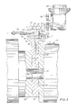
- FIG. 2 is a transverse cross-sectional view of an apparatus constructed in accordance with the invention installed in a plasticating extruder;
- FIG. 3 is a cross-sectional view taken along line 3-3 of FIG. 2; and
- FIG. 4 is an exploded perspective view of portions of the apparatus.
- Referring now to the drawing, and especially to FIG. 1 thereof, a plasticating extruder is shown schematically at 10.
Extruder 10 is in use, generating melted polymer for the continuous manufacture of items constructed of plastic material. In order to assure that the quality of the extrudate meets the requirements of the manufacturing process, a control system is utilized in connection with the operation of the extruder to monitor certain characteristics of the polymer melt and to operate the extruder in the manner necessary to attain the desired quality in the extrudate. An on-line rheometer 20, constructed in accordance with the present invention, is a part of that control system. - A portion of the polymer melt in the
extruder 10 is diverted from the main stream in the extruder to therheometer 20 through aninlet conduit 22 and is advanced by afirst metering pump 24 through anentrance conduit 26 to theentrance 28 to acapillary passage 30 of selected configuration and dimensions. The diverted polymer melt traverses thecapillary passage 30 and then leaves thecapillary passage 30 via anexit conduit 32. Asecond metering pump 34 advances the diverted polymer melt through anoutlet conduit 36 which communicates with theextruder 10 so that the diverted polymer melt is returned to the main stream of polymer melt in theextruder 10. A first pressure-responsive transducer 40 is placed at a location adjacent theentrance 28 and provides information indicative of the pressure P₁ in the polymer melt at that location in thecapillary passage 30. A second pressure-responsive transducer 42 is placed at a second location spaced downstream from the first location and provides information indicative of the pressure P₂ at the second location in thecapillary passage 30. The rate of flow of the polymer melt in thecapillary passage 30 is governed by the speed of thefirst metering pump 24 and that speed is determined by the speed of themotor 44 which drives themetering pump 24. The speed ofmotor 44 is controlled by acontroller 46 which itself is connected to acomputer 50.Temperature sensors computer 50 indicative of the temperature (T₁ and T₂) of the polymer melt adjacent each of the locations of the pressure-responsive transducers - In currently available rheometers of the type described, viscosity is calculated from the measured pressure drop (P₁ - P₂) along the
capillary passage 30 and the rate of flow of the polymer melt in thecapillary passage 30, while the temperature of the polymer melt is maintained at a constant value. Thus, temperature sensors, corresponding totemperature sensors capillary passage 30, the measure of the stress then being available in terms of the pressure drop (corresponding to P₁ - P₂) indicated by the pressure-responsive transducers similar to pressure-responsive transducers - The present invention reduces residence time and decreases response time, thereby enabling more truly on-line operation, by eliminating the requirement for control of the temperature of the diverted polymer melt, allowing
rheometer 20 to be placed in close proximity to extruder 10, or other process apparatus, for a reduction in residence time, during which the diverted polymer melt is outside the main stream, and a concomitant reduction in response time in the control system. Thus, in the present invention, the pressure drop P₁ - P₂ is maintained constant by controlling the speed of both the first and thesecond metering pumps first metering pump 24 then provides a measure of the rate of flow of the polymer melt traversing thecapillary passage 30, which rate of flow is an indication of the viscosity of the polymer melt. Since the speed of thefirst metering pump 24 is known with precision, the viscosity is determined with a high degree of accuracy. Since the temperature dependence of polymer materials at constant stress is well known, the maintenance of a constant stress on the polymer melt in thecapillary passage 30, that is, the maintenance of a constant pressure drop P₁ - P₂, enables the temperature information, as determined by T₁ and T₂ (preferably by averaging T₁ and T₂), to be utilized to relate the measurements to a known standard so that it is not necessary to control the temperature of the diverted polymer melt, but merely to measure the temperature and then correct the measured viscosity information, in accordance with the measured temperature, to derive the desired control information. In this manner, viscosity measurements are enabled independent of the temperature of the diverted polymer melt. The information pertaining to pressure drop (P₁ - P₂), rate of flow and temperature (T₁ and T₂) is directed tocomputer 50.Computer 50 then provides control information to a process computer which may be used in connection with the control of the operation of theextruder 10. - In order to maintain accuracy in the determination of viscosity, utilizing the above scheme, it is necessary to assure that the pressure drop (P₁ - P₂) is solely a result of the traverse of the
capillary passage 30 by the polymer melt, and that the measured pressures are not affected by any irregularities in the operation of the various components of therheometer 20. In currently available rheometers of the type described, the metering pumps usually are driven by a common motor and drive and the accuracy of the mechanical components is relied upon to maintain the same flow rate through both metering pumps so that the measured pressures within the capillary passage are unaffected by any variation in flow rate between the two metering pumps. However, it has been observed that unavoidable differences in the operating characteristics of the metering pumps, though small, will cause variations in the measured pressures significant enough to have a deleterious effect upon the accuracy of the control of the extruder. Accordingly,rheometer 20 includes means for driving thesecond metering pump 34 independent of thefirst metering pump 24, the means being illustrated in the form of asecond motor 60 controlled by asecond controller 62 connected tocomputer 50. A third pressure-responsive transducer 64 is locatedadjacent exit 66 from thecapillary passage 30 and provides information indicative of the pressure P₃ at the exit. The information provided by the third pressure-responsive transducer 64 is utilized by thecomputer 50 to operate thecontroller 62 so that themotor 60 actuates thesecond metering pump 34 at the speed necessary to maintain the pressure P₃ constant. By maintaining the exit pressure P3 constant, the pressure drop P₁ - P₂ is related solely to the characteristics of the polymer melt traversing thecapillary passage 30 and does not include any effects introduced by inaccuracies in the mechanical components of therheometer 20. Hence, the information provided bycomputer 50 is related solely to the characteristics of the polymer melt for accurate control of the process being carried out in the extruder. - The operation of the
second metering pump 34 independent of thefirst metering pump 24 enables the accomplishment of further significant measurements. Thus, in response to selected input into thecomputer 50, by means of aselector 68, the exit pressure P₃ can be changed to any selected constant pressure enabling the measurement of the viscosity of the polymer melt at different pressures, thereby enabling an evaluation of the response of viscosity to pressure. These measurements provide additional information enabling enhanced control of the quality of the extrudate produced by theextruder 10. - Turning now to FIGS. 2 and 3, there is illustrated a typical installation in which a
rheometer 20 is mounted upon anextruder 10 for on-line operation. Extruder 10 has abarrel 70 which includes anoutlet bore 72 at theoutput end 74 of theextruder 10. Amounting plate 76 is affixed to theend 74 of thebarrel 70 and has anaperture 78 which matches the outlet bore 72 of theextruder 10. Afurther orifice plate 80 is placed downstream of themounting plate 76.Rheometer 20 is secured to themounting plate 76 by means of abracket 81 which is integral with themounting plate 76 so as to be in very close proximity to the main stream of polymer melt passing from theextruder 10, through the outlet bore 72. Aninlet passage 82 in themounting plate 76 communicates with theaperture 78 and provides a relatively short conduit to theinlet conduit 22 of therheometer 20. Anoutlet passage 84 in themounting plate 76 also communicates with theaperture 78 and provides a relatively short conduit from theoutlet conduit 36 of therheometer 20 back to theaperture 78. A portion of the polymer melt is diverted from the main stream in the outlet bore 72 and theaperture 78 to theinlet passage 82 and is conducted to theinlet conduit 22 of therheometer 20. Thefirst metering pump 24 is in the form of a gear pump having a pair of gear-type impellers 86 (also see FIG. 4) coupled to thefirst motor 44 through adrive train 88 for rotation in apump chamber 89.Capillary passage 30 is in the form of aslot 90 in acapillary plate 92 and thepump chamber 89 communicates with theslot 90 throughentrance conduit 26 to deliver the diverted polymer melt from theinlet conduit 22 to thecapillary passage 30. The diverted polymer melt traverses thecapillary passage 30 and is delivered to thesecond metering pump 34 via theexit conduit 32.Second metering pump 34 also is in the form of a gear pump having a pair of gear-type impellers 96 coupled to thesecond motor 60 through adrive train 98 for rotation in apump chamber 99, independent of the rotation of theimpellers 86 of thefirst metering pump 24. Theoutlet conduit 36 communicates with thepump chamber 99 and enables return of the diverted polymer melt to the main stream in theaperture 78. Thus, it can be seen that therheometer 20 is placed in close proximity with the main stream of polymer melt for true on-line operation with a minimal intrusion into the manufacturing process, while enabling simplified installation for adapting therheometer 20 for use in connection with conventional extruders. The close proximity of therheometer 20 to the main stream of polymer melt assures that the residence time during which the diverted polymer melt resides in the rheometer, and outside the process main stream, is maintained at a minimum and the control system is able to respond relatively quickly to any changes in the viscosity of the polymer melt. The ability to accomplish the desired measurements without the necessity for controlling the temperature of the diverted polymer melt, as described above, enables the close proximity of therheometer 20 to the main stream with concomitant low residence time and quick response. In addition, the rheometer is more responsive since it is not necessary to change the temperature of the diverted polymer melt for the purpose of accomplishing an accurate viscosity measurement. All that is necessary is a measurement of the actual temperature of the diverted polymer melt while the polymer melt is under constant stress in the capillary passage. - As best seen in FIG. 4, as well as in FIGS. 2 and 3,
rheometer 20 preferably is constructed of assembled component parts which include afirst block 100 and asecond block 102 between which blocks 100 and 102 is interposed thecapillary plate 92 such that theslot 90, when placed between theblocks capillary passage 30. Theblocks capillary plate 92 are secured together, as with threadedfasteners 104, to establish an integral unit which may be dismantled at will. The metering pumps 24 and 34 likewise are secured to thesecond block 102, by means of threadedfasteners 106, each metering pump having adrive shaft 108 for coupling the impellers of the pump to the respective drive train. Thesecond block 102 also includes theinlet conduit 22, theentrance conduit 26, theexit conduit 32 and theoutlet conduit 36. Thefirst block 100 carries the pressure-responsive transducers temperature sensors - The
capillary plate 92 is relatively thin and the configuration and dimensions of thecapillary slot 90 are chosen to provide acapillary passage 30 of corresponding configuration and dimensions appropriate for enabling the desired measurements to be made in the particular polymer involved in the process being monitored. The various conduits in thesecond block 102 and the several transducers and sensors in thefirst block 100 are placed so as to be located appropriately relative to theslot 90.Capillary plate 92 is readily accessible for ease of cleaning and maintenance, and is replaced easily for adapting therheometer 20 for use with any one of a variety of materials and operating conditions. For example, any one of a series ofplates 92, each having aslot 90 of a different configuration and different dimensions, may be selected for a particular installation. The location of therheometer 20 renders the rheometer easily available for repair or replacement. That same location places therheometer 20 within easy reach for connection and disconnection with thecomputer 50, and for adapting the rheometer for other tasks involving the examination of the polymer melt such as, for example, the visual observation of the polymer melt for unwanted inclusions, as described in United States Patent No. 4,529,306. - It will be seen that the above-described apparatus and procedure enables truly on-line measurements for quicker response and more accurate control of manufacturing processes involving polymer melts; allows on-line measurements without the necessity for controlling the temperature of the diverted polymer melt, thereby enabling measurements to be made in close proximity to the main stream of polymer melt for decreased residence time, increased accuracy and quicker response; attains on-line measurements with a minimal intrusion into the process being monitored; permits increased versatility in the nature and extent of the information derived from on-line measurements of polymer melts, as well as increased accuracy in the information itself; allows ease of installation and use in connection with current manufacturing equipment and techniques; is adapted readily for use in connection with a wide variety of materials and operating conditions; provides a convenient station for additional sensing and observation devices available for monitoring the quality of the polymer melt; facilitates cleaning and general maintenance, as well as replacement of component parts either for repair or adaptation to different materials and specific operating conditions; and allows a simple and rugged construction for economical manufacture and reliable long-term service.
- It is to be understood that the above detailed description of embodiments of the invention is provided by way of example only. Various details of design, construction and procedure may be modified without departing from the true spirit and scope of the invention as set forth in the appended claims.
Claims (18)
Priority Applications (1)
| Application Number | Priority Date | Filing Date | Title |
|---|---|---|---|
| EP96119795A EP0769690B1 (en) | 1988-06-13 | 1989-05-25 | On-line rheological measurements |
Applications Claiming Priority (2)
| Application Number | Priority Date | Filing Date | Title |
|---|---|---|---|
| US206035 | 1988-06-13 | ||
| US07/206,035 US4817416A (en) | 1988-06-13 | 1988-06-13 | On-line rheological measurements |
Related Child Applications (2)
| Application Number | Title | Priority Date | Filing Date |
|---|---|---|---|
| EP96119795A Division EP0769690B1 (en) | 1988-06-13 | 1989-05-25 | On-line rheological measurements |
| EP96119795.1 Division-Into | 1996-12-10 |
Publications (3)
| Publication Number | Publication Date |
|---|---|
| EP0347055A2 true EP0347055A2 (en) | 1989-12-20 |
| EP0347055A3 EP0347055A3 (en) | 1990-12-27 |
| EP0347055B1 EP0347055B1 (en) | 1997-08-13 |
Family
ID=22764713
Family Applications (2)
| Application Number | Title | Priority Date | Filing Date |
|---|---|---|---|
| EP96119795A Expired - Lifetime EP0769690B1 (en) | 1988-06-13 | 1989-05-25 | On-line rheological measurements |
| EP89305324A Expired - Lifetime EP0347055B1 (en) | 1988-06-13 | 1989-05-25 | On-line rheological measurements |
Family Applications Before (1)
| Application Number | Title | Priority Date | Filing Date |
|---|---|---|---|
| EP96119795A Expired - Lifetime EP0769690B1 (en) | 1988-06-13 | 1989-05-25 | On-line rheological measurements |
Country Status (5)
| Country | Link |
|---|---|
| US (1) | US4817416A (en) |
| EP (2) | EP0769690B1 (en) |
| JP (1) | JPH0238841A (en) |
| CA (1) | CA1316721C (en) |
| DE (2) | DE68928252T2 (en) |
Cited By (3)
| Publication number | Priority date | Publication date | Assignee | Title |
|---|---|---|---|---|
| DE19505250C1 (en) * | 1995-02-16 | 1996-08-22 | Goettfert Werkstoff Pruefmasch | Measurement of stretch elastic characteristics of extruded molten polymer |
| EP1260348A3 (en) * | 2001-05-09 | 2004-01-02 | Technoplast Kunststofftechnik Gesellschaft m.b.H. | Method and device for adapting an extruder nozzle to an extruder |
| EP1609581A2 (en) | 2004-06-25 | 2005-12-28 | Technoplast Kunststofftechnik Gesellschaft m.b.H. | Method of manufacturing profiles from thermoplastic material |
Families Citing this family (45)
| Publication number | Priority date | Publication date | Assignee | Title |
|---|---|---|---|---|
| JPH07119685B2 (en) * | 1987-04-17 | 1995-12-20 | 東洋紡績株式会社 | Capillary viscometer |
| DE3921841A1 (en) * | 1989-07-03 | 1991-01-10 | Goettfert Werkstoff Pruefmasch | REAL-TIME CAPILLARY RHEOMETER ARRANGEMENT |
| US4992487A (en) * | 1990-01-09 | 1991-02-12 | E. I. Du Pont De Nemours And Company | Method for determining flow behavior index and using index to control polymer rheology and physical properties |
| US5014545A (en) * | 1990-09-19 | 1991-05-14 | E. I. Du Pont De Nemours And Company | Apparatus for determining flow behavior index |
| GB2250601B (en) * | 1990-12-04 | 1994-04-06 | Schlumberger Services Petrol | Rheometer |
| US5105655A (en) * | 1991-01-18 | 1992-04-21 | Bell Communications Research, Inc. | Rheological device for in situ measurements of photo polymerization kinetics |
| DE4236407C2 (en) * | 1992-10-28 | 1996-02-15 | Goettfert Werkstoff Pruefmasch | Method and device for continuous viscosity measurement |
| US5277058A (en) * | 1992-11-23 | 1994-01-11 | Kalyon Dilhan M | Adjustable gap rheometer |
| US5347852A (en) * | 1993-03-11 | 1994-09-20 | Rheometrics, Inc. | On-line rheological measurements for process control |
| US5532593A (en) * | 1993-11-01 | 1996-07-02 | The Regents Of The University Of California | Nuclear magnetic resonance imaging rheometer |
| US5734093A (en) * | 1995-12-19 | 1998-03-31 | The Dow Chemical Company | Method and apparatus for determining physical properties of a gas for use in rheometry |
| US5708197A (en) * | 1996-05-07 | 1998-01-13 | Polymer Processing Institute | Helical barrel rheometer |
| US5974866A (en) * | 1997-08-29 | 1999-11-02 | General Electric Company | On-line rheometer device |
| DE19741674A1 (en) * | 1997-09-22 | 1999-03-25 | Haake Gmbh Geb | Mixer for viscoelastic materials |
| US6196058B1 (en) | 1998-03-12 | 2001-03-06 | Consolidated Papers, Inc. | On-line viscosity measurement system |
| WO2000066993A1 (en) * | 1999-04-29 | 2000-11-09 | Dynisco Polymer Test, Inc. | Apparatus and method for measuring fluid properties |
| US6182503B1 (en) | 1999-07-01 | 2001-02-06 | Rheometric Scientific, Inc. | On-line rheological measurement for process control |
| GB0002192D0 (en) * | 2000-01-31 | 2000-03-22 | Borealis Polymers Oy | Rheometry |
| JP2004503371A (en) * | 2000-06-15 | 2004-02-05 | ダウ グローバル テクノロジーズ インコーポレイティド | Method and apparatus for preparing a composition using a side-flow ultrasonic device |
| US6534010B2 (en) * | 2000-12-07 | 2003-03-18 | The Goodyear Tire & Rubber Company | Apparatus for process line testing |
| US20020072827A1 (en) | 2000-12-11 | 2002-06-13 | Sentmanat Martin Lamar | Apparatus and method for process line testing |
| CN100443868C (en) | 2001-11-09 | 2008-12-17 | 埃克森美孚化学专利公司 | On-Line Measurement and Control of Polymer Properties Using Raman Spectroscopy |
| US6691561B2 (en) * | 2002-04-15 | 2004-02-17 | Gerneral Electric Company | Rheological measurement process |
| US6691558B1 (en) | 2002-07-31 | 2004-02-17 | General Electric Company | In-line rheometer device and method |
| AU2003302739A1 (en) | 2003-01-06 | 2004-08-10 | Exxonmobil Chemical Patents Inc. | On-line measurement and control of polymer product properties by raman spectroscopy |
| DE102004022653A1 (en) * | 2004-05-07 | 2005-12-15 | Zimmer Ag | Method for process control in the production of polyesters or copolyesters |
| US7505127B2 (en) | 2005-07-22 | 2009-03-17 | Exxonmobil Chemical Patents Inc. | On-line raman analysis and control of a high pressure reaction system |
| US7505129B2 (en) | 2005-07-22 | 2009-03-17 | Exxonmobil Chemical Patents Inc. | On-line analysis of polymer properties for control of a solution phase reaction system |
| US7483129B2 (en) | 2005-07-22 | 2009-01-27 | Exxonmobil Chemical Patents Inc. | On-line properties analysis of a molten polymer by raman spectroscopy for control of a mixing device |
| DE102005062718A1 (en) * | 2005-12-28 | 2007-07-05 | Robert Bosch Gmbh | Device for determining the viscosity of liquids |
| DE102006034390A1 (en) * | 2006-07-25 | 2008-01-31 | Jado Extruvision Gmbh | rheometer |
| CN1959372B (en) * | 2006-11-28 | 2011-01-05 | 中北大学 | Rheological behavior measuring instrument for system of supercutical fluid - polymer |
| DE102007033969B4 (en) * | 2007-07-19 | 2018-09-20 | Gneuss Gmbh | Device for measuring the viscosity of plastic melts |
| JP5094309B2 (en) * | 2007-09-26 | 2012-12-12 | 三洋電機株式会社 | Communication device and charger |
| US7832257B2 (en) * | 2007-10-05 | 2010-11-16 | Halliburton Energy Services Inc. | Determining fluid rheological properties |
| CN101430267B (en) * | 2008-12-12 | 2010-09-08 | 湖南工业大学 | A method and device for testing rheological properties of polymer composite materials |
| DE102010004794A1 (en) | 2009-02-12 | 2010-08-19 | Oerlikon Textile Gmbh & Co. Kg | Method for testing polymer melt, involves producing polymer melt through melt source, and determining parameter i.e. purity level, of polymer melt with melt streams, where melt streams are supplied to extrusion bodies |
| CN104267177A (en) * | 2014-09-10 | 2015-01-07 | 常州大学 | Plastic melt PVT (pressure, volume and temperature) characteristic experimental device |
| EP3220126A1 (en) * | 2016-03-17 | 2017-09-20 | iVON GmbH | Device for determining the viscosity of liquids |
| AT518911B1 (en) * | 2016-07-18 | 2022-01-15 | Erema Eng Recycling Maschinen & Anlagen Gmbh | Process and device for online determination of the viscosity of a polymer |
| US10899059B2 (en) * | 2017-05-12 | 2021-01-26 | Kuraray Europe Gmbh | Method for producing films based on plasticized polyvinyl acetal having a predefined viscosity |
| US11080440B2 (en) | 2017-06-27 | 2021-08-03 | International Business Machines Corporation | Characterizing fluid flow at field conditions |
| JP2019116023A (en) * | 2017-12-27 | 2019-07-18 | 住友ゴム工業株式会社 | Rubber extrusion apparatus and rubber extrusion method |
| CN109031941B (en) * | 2018-06-15 | 2024-07-26 | 康辉新材料科技有限公司 | Resin viscosity control system and detection method |
| CN109366933A (en) * | 2018-11-27 | 2019-02-22 | 武汉轻工大学 | An online detection system for metal-polymer composite material processing |
Family Cites Families (16)
| Publication number | Priority date | Publication date | Assignee | Title |
|---|---|---|---|---|
| US3116630A (en) * | 1960-07-21 | 1964-01-07 | Sinclair Research Inc | Continuous viscosimeter |
| DE1168123B (en) * | 1961-02-28 | 1964-04-16 | Bayer Ag | Device for determining the viscosity of liquids |
| US3138950A (en) * | 1961-03-20 | 1964-06-30 | Phillips Petroleum Co | Apparatus for concurrent measurement of polymer melt viscosities at high and low shear rates |
| JPS4526837Y1 (en) * | 1966-05-13 | 1970-10-19 | ||
| GB1254867A (en) * | 1967-10-05 | 1971-11-24 | Toray Industries | Apparatus and method for continuously determining viscosity |
| US3559464A (en) * | 1969-11-13 | 1971-02-02 | Exxon Research Engineering Co | Rheometer for continuous monitoring of a plastic |
| NL152378B (en) * | 1973-05-04 | 1977-02-15 | Itt | DEVICE FOR REGULATING THE VISCOSITY OF A LIQUID. |
| DE2751225C3 (en) * | 1977-11-16 | 1981-08-13 | Werner & Pfleiderer, 7000 Stuttgart | Device with a melt index measuring device arranged after the sieve pack of a screw extruder and a method for regulating the viscosity of melted plastic that is to be molded |
| US4241602A (en) * | 1979-04-20 | 1980-12-30 | Seismograph Service Corporation | Rheometer |
| SU817531A1 (en) * | 1979-06-22 | 1981-03-30 | Новополоцкое Отделение Предприятияп/Я B-2913 | Device for investigating rheological characteristics of polymers |
| SU873035A1 (en) * | 1980-02-18 | 1981-10-15 | Предприятие П/Я М-5593 | Method of continuous determination of plastic dispersion system rheologic properties |
| US4529306A (en) | 1983-06-13 | 1985-07-16 | Flow Vision, Inc. | Apparatus and method for polymer melt stream analysis |
| JPS6096013U (en) * | 1983-12-07 | 1985-06-29 | 西川ゴム工業株式会社 | Device for measuring physical properties of polymer materials being processed |
| SU1155914A1 (en) * | 1983-12-15 | 1985-05-15 | Предприятие П/Я М-5593 | Method and device for determining reological characteristics of plastic lubricants |
| SU1183870A1 (en) * | 1984-02-27 | 1985-10-07 | Львовский Ордена Ленина Политехнический Институт Им.Ленинского Комсомола | Apparatus for measuring rheological parameters of visco-plastic liquids |
| SU1283618A1 (en) * | 1985-07-19 | 1987-01-15 | Львовский политехнический институт им.Ленинского комсомола | Device for determining rheologic characteristics of viscous-plastic liquids |
-
1988
- 1988-06-13 US US07/206,035 patent/US4817416A/en not_active Expired - Lifetime
-
1989
- 1989-05-17 CA CA000599920A patent/CA1316721C/en not_active Expired - Fee Related
- 1989-05-25 DE DE68928252T patent/DE68928252T2/en not_active Expired - Fee Related
- 1989-05-25 DE DE68929247T patent/DE68929247T2/en not_active Expired - Fee Related
- 1989-05-25 EP EP96119795A patent/EP0769690B1/en not_active Expired - Lifetime
- 1989-05-25 EP EP89305324A patent/EP0347055B1/en not_active Expired - Lifetime
- 1989-06-13 JP JP1148573A patent/JPH0238841A/en active Granted
Cited By (4)
| Publication number | Priority date | Publication date | Assignee | Title |
|---|---|---|---|---|
| DE19505250C1 (en) * | 1995-02-16 | 1996-08-22 | Goettfert Werkstoff Pruefmasch | Measurement of stretch elastic characteristics of extruded molten polymer |
| EP1260348A3 (en) * | 2001-05-09 | 2004-01-02 | Technoplast Kunststofftechnik Gesellschaft m.b.H. | Method and device for adapting an extruder nozzle to an extruder |
| EP1609581A2 (en) | 2004-06-25 | 2005-12-28 | Technoplast Kunststofftechnik Gesellschaft m.b.H. | Method of manufacturing profiles from thermoplastic material |
| AT414225B (en) * | 2004-06-25 | 2006-10-15 | Technoplast Kunststofftechnik | PROCESS FOR PRODUCING PROFILES FROM THERMOPLASTIC PLASTIC |
Also Published As
| Publication number | Publication date |
|---|---|
| CA1316721C (en) | 1993-04-27 |
| EP0347055A3 (en) | 1990-12-27 |
| DE68929247T2 (en) | 2001-04-05 |
| EP0347055B1 (en) | 1997-08-13 |
| EP0769690A2 (en) | 1997-04-23 |
| DE68929247D1 (en) | 2000-10-12 |
| DE68928252D1 (en) | 1997-09-18 |
| US4817416A (en) | 1989-04-04 |
| EP0769690A3 (en) | 1997-05-07 |
| JPH0526135B2 (en) | 1993-04-15 |
| EP0769690B1 (en) | 2000-09-06 |
| JPH0238841A (en) | 1990-02-08 |
| DE68928252T2 (en) | 1997-12-18 |
Similar Documents
| Publication | Publication Date | Title |
|---|---|---|
| US4817416A (en) | On-line rheological measurements | |
| US5347852A (en) | On-line rheological measurements for process control | |
| US6405579B1 (en) | Scaleless on-line rheometer device | |
| US4213747A (en) | Method of and apparatus for controlling the viscosity of molten plastics material which is to be moulded | |
| US4228815A (en) | Measurement and control of multicomponent liquid systems | |
| US3357049A (en) | Extruder control system | |
| CA1147922A (en) | Method of extruding and shaping thermoplastic material | |
| US7018191B2 (en) | Plastics extruder dimension and viscosity control system | |
| US20060138690A1 (en) | Method for producing profiles made of thermoplastic material | |
| JPS6096432A (en) | Device for working and forwarding thermoplastic resin | |
| US20040020272A1 (en) | In-line rheometer device and method | |
| US4449395A (en) | Pheological measurement method and apparatus | |
| US3252320A (en) | Melt index apparatus | |
| US3493345A (en) | Method of controlling polymer viscosity during synthesis by utilizing motor load | |
| US4228683A (en) | Method of determining liquid flow in a conduit | |
| US4933886A (en) | Device for measuring melt flow index | |
| US6182503B1 (en) | On-line rheological measurement for process control | |
| CA1075489A (en) | Measurement and control of multicomponent liquid systems | |
| US3209581A (en) | Continuous melt indexer | |
| US4165631A (en) | Instrument for the continuous measurement of viscosity, especially of bitumens | |
| US4573345A (en) | Melt rheometer control | |
| US3234781A (en) | Viscosity monitor | |
| US3008326A (en) | Apparatus for measuring viscosity | |
| JPH0430526Y2 (en) | ||
| JPH05131521A (en) | Continuous measuring method for molten resin and its device |
Legal Events
| Date | Code | Title | Description |
|---|---|---|---|
| PUAI | Public reference made under article 153(3) epc to a published international application that has entered the european phase |
Free format text: ORIGINAL CODE: 0009012 |
|
| AK | Designated contracting states |
Kind code of ref document: A2 Designated state(s): CH DE FR GB IT LI NL |
|
| PUAL | Search report despatched |
Free format text: ORIGINAL CODE: 0009013 |
|
| AK | Designated contracting states |
Kind code of ref document: A3 Designated state(s): CH DE FR GB IT LI NL |
|
| RHK1 | Main classification (correction) |
Ipc: G01N 11/08 |
|
| 17P | Request for examination filed |
Effective date: 19910618 |
|
| 17Q | First examination report despatched |
Effective date: 19930305 |
|
| GRAG | Despatch of communication of intention to grant |
Free format text: ORIGINAL CODE: EPIDOS AGRA |
|
| GRAH | Despatch of communication of intention to grant a patent |
Free format text: ORIGINAL CODE: EPIDOS IGRA |
|
| GRAH | Despatch of communication of intention to grant a patent |
Free format text: ORIGINAL CODE: EPIDOS IGRA |
|
| GRAA | (expected) grant |
Free format text: ORIGINAL CODE: 0009210 |
|
| ITF | It: translation for a ep patent filed | ||
| AK | Designated contracting states |
Kind code of ref document: B1 Designated state(s): CH DE FR GB IT LI NL |
|
| XX | Miscellaneous (additional remarks) |
Free format text: TEILANMELDUNG 96119795.1 EINGEREICHT AM 10/12/96. |
|
| REG | Reference to a national code |
Ref country code: CH Ref legal event code: EP |
|
| REF | Corresponds to: |
Ref document number: 68928252 Country of ref document: DE Date of ref document: 19970918 |
|
| REG | Reference to a national code |
Ref country code: CH Ref legal event code: NV Representative=s name: E. BLUM & CO. PATENTANWAELTE |
|
| ET | Fr: translation filed | ||
| PLBE | No opposition filed within time limit |
Free format text: ORIGINAL CODE: 0009261 |
|
| STAA | Information on the status of an ep patent application or granted ep patent |
Free format text: STATUS: NO OPPOSITION FILED WITHIN TIME LIMIT |
|
| 26N | No opposition filed | ||
| PGFP | Annual fee paid to national office [announced via postgrant information from national office to epo] |
Ref country code: GB Payment date: 20010523 Year of fee payment: 13 |
|
| PGFP | Annual fee paid to national office [announced via postgrant information from national office to epo] |
Ref country code: DE Payment date: 20010528 Year of fee payment: 13 |
|
| PGFP | Annual fee paid to national office [announced via postgrant information from national office to epo] |
Ref country code: CH Payment date: 20010529 Year of fee payment: 13 |
|
| PGFP | Annual fee paid to national office [announced via postgrant information from national office to epo] |
Ref country code: NL Payment date: 20010531 Year of fee payment: 13 |
|
| PGFP | Annual fee paid to national office [announced via postgrant information from national office to epo] |
Ref country code: FR Payment date: 20010601 Year of fee payment: 13 |
|
| REG | Reference to a national code |
Ref country code: GB Ref legal event code: IF02 |
|
| PG25 | Lapsed in a contracting state [announced via postgrant information from national office to epo] |
Ref country code: GB Free format text: LAPSE BECAUSE OF NON-PAYMENT OF DUE FEES Effective date: 20020525 |
|
| PG25 | Lapsed in a contracting state [announced via postgrant information from national office to epo] |
Ref country code: LI Free format text: LAPSE BECAUSE OF NON-PAYMENT OF DUE FEES Effective date: 20020531 Ref country code: CH Free format text: LAPSE BECAUSE OF NON-PAYMENT OF DUE FEES Effective date: 20020531 |
|
| PG25 | Lapsed in a contracting state [announced via postgrant information from national office to epo] |
Ref country code: NL Free format text: LAPSE BECAUSE OF NON-PAYMENT OF DUE FEES Effective date: 20021201 |
|
| PG25 | Lapsed in a contracting state [announced via postgrant information from national office to epo] |
Ref country code: DE Free format text: LAPSE BECAUSE OF NON-PAYMENT OF DUE FEES Effective date: 20021203 |
|
| GBPC | Gb: european patent ceased through non-payment of renewal fee |
Effective date: 20020525 |
|
| REG | Reference to a national code |
Ref country code: CH Ref legal event code: PL |
|
| PG25 | Lapsed in a contracting state [announced via postgrant information from national office to epo] |
Ref country code: FR Free format text: LAPSE BECAUSE OF NON-PAYMENT OF DUE FEES Effective date: 20030131 |
|
| NLV4 | Nl: lapsed or anulled due to non-payment of the annual fee |
Effective date: 20021201 |
|
| REG | Reference to a national code |
Ref country code: FR Ref legal event code: ST |
|
| PG25 | Lapsed in a contracting state [announced via postgrant information from national office to epo] |
Ref country code: IT Free format text: LAPSE BECAUSE OF NON-PAYMENT OF DUE FEES;WARNING: LAPSES OF ITALIAN PATENTS WITH EFFECTIVE DATE BEFORE 2007 MAY HAVE OCCURRED AT ANY TIME BEFORE 2007. THE CORRECT EFFECTIVE DATE MAY BE DIFFERENT FROM THE ONE RECORDED. Effective date: 20050525 |