EP0346861A1 - Buckle - Google Patents
Buckle Download PDFInfo
- Publication number
- EP0346861A1 EP0346861A1 EP89110782A EP89110782A EP0346861A1 EP 0346861 A1 EP0346861 A1 EP 0346861A1 EP 89110782 A EP89110782 A EP 89110782A EP 89110782 A EP89110782 A EP 89110782A EP 0346861 A1 EP0346861 A1 EP 0346861A1
- Authority
- EP
- European Patent Office
- Prior art keywords
- resilient
- female member
- engaging
- shaped
- pair
- Prior art date
- Legal status (The legal status is an assumption and is not a legal conclusion. Google has not performed a legal analysis and makes no representation as to the accuracy of the status listed.)
- Granted
Links
- 238000003780 insertion Methods 0.000 claims description 2
- 230000037431 insertion Effects 0.000 claims description 2
- 238000010276 construction Methods 0.000 description 3
- 230000008878 coupling Effects 0.000 description 3
- 238000010168 coupling process Methods 0.000 description 3
- 238000005859 coupling reaction Methods 0.000 description 3
- 238000004519 manufacturing process Methods 0.000 description 3
- 230000002035 prolonged effect Effects 0.000 description 2
- 239000004677 Nylon Substances 0.000 description 1
- 229930182556 Polyacetal Natural products 0.000 description 1
- 239000004743 Polypropylene Substances 0.000 description 1
- 238000012986 modification Methods 0.000 description 1
- 230000004048 modification Effects 0.000 description 1
- 229920001778 nylon Polymers 0.000 description 1
- 229920006324 polyoxymethylene Polymers 0.000 description 1
- -1 polypropylene Polymers 0.000 description 1
- 229920001155 polypropylene Polymers 0.000 description 1
- 238000000926 separation method Methods 0.000 description 1
- 229920003002 synthetic resin Polymers 0.000 description 1
- 239000000057 synthetic resin Substances 0.000 description 1
Images

Classifications
-
- A—HUMAN NECESSITIES
- A44—HABERDASHERY; JEWELLERY
- A44B—BUTTONS, PINS, BUCKLES, SLIDE FASTENERS, OR THE LIKE
- A44B11/00—Buckles; Similar fasteners for interconnecting straps or the like, e.g. for safety belts
- A44B11/02—Buckles; Similar fasteners for interconnecting straps or the like, e.g. for safety belts frictionally engaging surface of straps
-
- A—HUMAN NECESSITIES
- A44—HABERDASHERY; JEWELLERY
- A44B—BUTTONS, PINS, BUCKLES, SLIDE FASTENERS, OR THE LIKE
- A44B11/00—Buckles; Similar fasteners for interconnecting straps or the like, e.g. for safety belts
- A44B11/25—Buckles; Similar fasteners for interconnecting straps or the like, e.g. for safety belts with two or more separable parts
- A44B11/26—Buckles; Similar fasteners for interconnecting straps or the like, e.g. for safety belts with two or more separable parts with push-button fastenings
- A44B11/266—Buckles; Similar fasteners for interconnecting straps or the like, e.g. for safety belts with two or more separable parts with push-button fastenings with at least one push-button acting parallel to the main plane of the buckle and perpendicularly to the direction of the fastening action
-
- A—HUMAN NECESSITIES
- A44—HABERDASHERY; JEWELLERY
- A44B—BUTTONS, PINS, BUCKLES, SLIDE FASTENERS, OR THE LIKE
- A44B11/00—Buckles; Similar fasteners for interconnecting straps or the like, e.g. for safety belts
- A44B11/25—Buckles; Similar fasteners for interconnecting straps or the like, e.g. for safety belts with two or more separable parts
-
- Y—GENERAL TAGGING OF NEW TECHNOLOGICAL DEVELOPMENTS; GENERAL TAGGING OF CROSS-SECTIONAL TECHNOLOGIES SPANNING OVER SEVERAL SECTIONS OF THE IPC; TECHNICAL SUBJECTS COVERED BY FORMER USPC CROSS-REFERENCE ART COLLECTIONS [XRACs] AND DIGESTS
- Y10—TECHNICAL SUBJECTS COVERED BY FORMER USPC
- Y10T—TECHNICAL SUBJECTS COVERED BY FORMER US CLASSIFICATION
- Y10T24/00—Buckles, buttons, clasps, etc.
- Y10T24/40—Buckles
- Y10T24/4002—Harness
- Y10T24/4012—Clamping
- Y10T24/4016—Pivoted part or lever
Definitions
- the present invention relates to a buckle for fastening a closure flap of a bag, a rucksack or the like, and also for fastening straps, belts or suspenders of a shoe, a boot, trousers, a skirt or the like.
- Japanese Utility Model Laid-Open Publication No. 60-31809 discloses a buckle for fastening belts of shoe which buckle comprises, as shown in FIGS. 4A, 4B and 4C of the accompanying drawings, interlocking male and female members A, B.
- the male member A has on its bottom surface a pair of resilient legs C, C, each having on its outer side a stepped portion which is engageable with the edge D of an aperture in the female member B as the male member A is pressed against the female member B so as to force the legs C, C into the aperture from the top side of the female member B in a snap action.
- the female member B has a pair of resilient arms E, E having a pair of inwardly directed pushing portions F, F.
- the female member B further has a hollow chamber H formed therein and a cantilever resilient member G supported on the left side and on the bottom surface (as viewed in FIG.
- such a conventional buckle is disadvantageous in that, since the cantilever resilient member G of the female member B continues to urge the bottom surface of the male member A throughout while the male member A is coupled with the female member B, the cantilever resilient member G is liable to fatigue, namely, has a tendency to lose resiliecy so that the the buckle as a whole lacks in durability. Furthermore, the cantilever resilient member is formed in such a shape to extend into the hollow chamber H, it is not simple to manufacture.
- a buckle comprising: a male member having a tongue-shaped presser having on its bottom side a pair of engaging legs each having on its inner side a stepped portion; a female member in the form of a case having in its top wall a central aperture for insertion of the engaging legs thereinto, the female member having a pair of resilient arms mounted, one on each side thereof, each resilient arm extending from one end of the female member and terminating in a free end portion for resilient angular movement about its proximal end, each free end portion having on its inner side a hook-shaped engaging means adapted for engagement with the stepped portion of the engaging legs when the engaging legs are inserted into the central aperture; and the tongue-shaped presser further having on its bottom side a pair of resilient pieces, the free end portions further having on their respective inner sides abutment portions adapted to compress the distal portions of the resilient pieces against the resiliency thereof as the resilient arms are angularly moved in the direction to bring the hook-shaped engaging means out of engagement with
- the principle of the present invention is particularly useful when embodied in a buckle such as shown in FIGS. 3A through 3C.
- the buckle comprises a male member 1 (FIGS. 1A through 1D) and a female member 10 (FIGS. 2A through 2E).
- Each of the male and female members 1, 10 is molded of a synthetic resin such as polyacetal, nylon or polypropylene.
- the male member 1 includes an attachment plate 3 and a tongue-shaped presser 2 pivotally mounted on the attachment plate 3 by means of a pair of aligned pins 4, 4 provided on one end of and on the opposite sides of the tongue-shaped presser 2.
- the tongue-shaped presser 2 has on its bottom side a pair of engaging legs 5, 5 and a pair of resilient pieces 6, 6, all integrally formed on the tongue-shaped presser 2.
- the two engaging legs 5, 5 are separated, laterally of the tongue-shaped presser 2, from each other; while the two resilient pieces 6, 6 are, similarly, separated, laterally of the tongue-shaped presser 2, from each other.
- the two resilient pieces 6, 6 are disposed adjacent to and extend parallel to the two engaging legs 5, 5, respectively, longitudinally of the tongue-shaped presser 2.
- each of the engaging legs 5, 5 has at its top a beveled surface 7 and at the middle on its inner or opposed side, a stepped portion 8.
- the attachment plate 3 is provided at its bottom side with a pair of studs 21, 21.
- the studs 21, 21 pass through a strap, a belt, a suspender or the like (hereinafter referred to as strap) 22 first and then are secured at their distal ends to a base plate 23, so that the male member 1 is firmly attached to the strap 22.
- the female member 10 is generally in the form of a case having in its top wall a central aperture 11 into which the two engaging legs 5, 5 and the two resilient pieces 6, 6 of the male member 1 is adapted to be inserted.
- the female member 10 also has a pair of resilient arms 12, 12 mounted, one on each of the opposed sides thereof.
- Each resilient arm 12 is integrally formed with and extends lengthwise from one end (right end as viewed in FIGS. 2A through 2C) of the female member 10 and terminate in a free end portion 14 so that the resilient arms 12, 12 are angularly movable about the respective proximal ends 13, 13 in resilient manner towards and away from each other.
- the free end portion 14 has at its inner side an extension 15 which is directed inwardly of the female member 10.
- the extension 15 has at its distal end a hook-shaped engaging means 16 adapted for snap engagement with the stepped portion 8 of the engaging leg 5 of the male member 1 when the engaging legs 5 are forced into the central aperture 11 of the female member 10.
- Each free end portion 14 has on its inner side a protuberant abutment portion 18 which faces the outer side of the hook-shaped engaging means 16.
- the abutment portions 18, 18 are adapted to compress the distal portions 9, 9 of the respective resilient pieces 6, 6 against the resiliency thereof when the resilient arms 12, 12 are angularly moved towards each other, thus exerting force tending to move the tongue-shaped presser 2 upwardly, thereby snappingly uncoupling the tongue-shaped presser 2 of the male member 1 from the female member 10.
- each abutment portion 18 may have at its distal end a slant surface 19 facing obliquely upwardly so as to more effectively exert forces tending to move the tongue-shaped presser 2 upwardly.
- Each resilient arm 12 has on its outer side a grip plate 20 which extends perpendicularly to the resilient arm 12.
- the female member 10 has on its bottom side three studs 24, 24, 24 which, as shown in FIG. 3B, pass through the strap 25 first and are fastened at their distal ends to a base plate 26 for firm attachment of the strap 25 to the female member 10. Coupling and uncoupling operation of the male member 1 and female member 10 is now described hereinbelow.
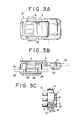
- FIGS. 3A through 3C shows the male member 1 and the female member 10 which have been resultantly coupled with each other.
- FIG. 3B shows that the male member 1 and the female member 10 are attached to the respective straps 22, 25, so that the male member 1 and the female member 10 being coupled together has given rise to the respective straps 22, 25 being joined with each other.
- the grip plates 20, 20 of the resilient arms 12, 12 are compressed by fingers of a wearer.
- the resilient arms 12, 12 angularly move about their proximal ends 13, 13 against their own resiliency so as to move their free end portions 14, 14 towards each other until the hook-shaped engaging means 16, 16 provided on the extension 15, 15 of the free end portion 14, 14 come out of engagement with the stepped portions 8, 8 of the engaging legs 5, 5, of the tongue-shaped presser 2.
- the tongue-shaped presser of the male member automatically spring apart from the female member, so that the separation of the male and female members can be carried out by a single movement of just compressing the grip plates. This advantageously dispenses with an additional work of manually separating the tongue-shaped presser of the male member apart from the female member.
- the resilient pieces are bent or are subjected to deformation by the abutment portion only when the grip plates are compressed to uncouple the male and female member, so that the resilient pieces can maintain their resiliency and hence the buckles as a whole can wear for a prolonged period of time.
- the resilient pieces for springing apart the male member from the female member is of such simple construction as to just stand upright on the flat bottom side of the tongue-shaped presser, so that the resilient pieces are easier to form, and hence the buckle as a whole are easier to manufacture.
Landscapes
- Buckles (AREA)
Abstract
Description
- The present invention relates to a buckle for fastening a closure flap of a bag, a rucksack or the like, and also for fastening straps, belts or suspenders of a shoe, a boot, trousers, a skirt or the like.
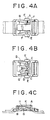
- Japanese Utility Model Laid-Open Publication No. 60-31809 discloses a buckle for fastening belts of shoe which buckle comprises, as shown in FIGS. 4A, 4B and 4C of the accompanying drawings, interlocking male and female members A, B. The male member A has on its bottom surface a pair of resilient legs C, C, each having on its outer side a stepped portion which is engageable with the edge D of an aperture in the female member B as the male member A is pressed against the female member B so as to force the legs C, C into the aperture from the top side of the female member B in a snap action. The female member B has a pair of resilient arms E, E having a pair of inwardly directed pushing portions F, F. When the two arms E, E are pressed toward each other, the pusher portion F, F pushes the legs C, C so as to resiliently bend the same inwardly, thereby bringing the stepped portions out of engagement with the edge D of the aperture, so that the male member A is uncoupled from the female member B. The female member B further has a hollow chamber H formed therein and a cantilever resilient member G supported on the left side and on the bottom surface (as viewed in FIG. 4C) of the female member B and extending into the hollow chamber H so as to normally urge at its distal end K the bottom surface of the male member A upwardly, so that, when the male member A is uncoupled from the female member B, the male member A springs up under the resiliency of the cantilever resilient member G.
- However, such a conventional buckle is disadvantageous in that, since the cantilever resilient member G of the female member B continues to urge the bottom surface of the male member A throughout while the male member A is coupled with the female member B, the cantilever resilient member G is liable to fatigue, namely, has a tendency to lose resiliecy so that the the buckle as a whole lacks in durability. Furthermore, the cantilever resilient member is formed in such a shape to extend into the hollow chamber H, it is not simple to manufacture.
- With the drawbacks in view, it is an object of the present invention to provide a backle having resilient means for springing the male member apart from the female member the moment the former is uncoupled from the latter, the resilient means being simple in construction, thus easy to form and capable of maintaining resiliency despite of long use, so that the buckle as a whole is easy to manufacture and wears well for a prolonged period of time.
- According to the present invention, there is provided a buckle comprising: a male member having a tongue-shaped presser having on its bottom side a pair of engaging legs each having on its inner side a stepped portion; a female member in the form of a case having in its top wall a central aperture for insertion of the engaging legs thereinto, the female member having a pair of resilient arms mounted, one on each side thereof, each resilient arm extending from one end of the female member and terminating in a free end portion for resilient angular movement about its proximal end, each free end portion having on its inner side a hook-shaped engaging means adapted for engagement with the stepped portion of the engaging legs when the engaging legs are inserted into the central aperture; and the tongue-shaped presser further having on its bottom side a pair of resilient pieces, the free end portions further having on their respective inner sides abutment portions adapted to compress the distal portions of the resilient pieces against the resiliency thereof as the resilient arms are angularly moved in the direction to bring the hook-shaped engaging means out of engagement with the stepped portion of the engaging legs.
- Many other advantages and features of the present invention will become manifest to those versed in the art upon making reference to the detailed description and the accompanying sheets of drawings in which preferred structural embodiments incorporating the principles of the present invention are shown by way of illustrative example.
- FIG. 1A is a plan view of a male member of a buckle embodying the present invention;
- FIG. 1B is a side elevational view, partly in cross section, of FIG. 1A;
- FIG. 1C is a bottom view of FIG. 1A;
- FIG. 1D is a cross sectional view taken on line A-A of FIG. 1C;
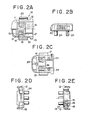
- FIG. 2A is a plan view, partly in cross section, of a female member of the buckle;
- FIG. 2B is a side elevational view, partly in cross section, of FIG. 2A;
- FIG. 2C is a bottom view of FIG. 2A;
- FIG. 2D is a front elevational view of FIG. 2A;
- FIG. 2E is a rear elevational view, partly in cross section, of FIG. 2A;
- FIG. 3A is a plan view of the buckle, showing the male and female members in a coupled posture;
- FIG. 3B is a side elevational view of FIG. 3A;
- FIG. 3C is a rear elevational view, partly in cross section, of FIG. 3A;
- FIG. 4A is a plan view of a buckle according to a prior art, showing male and female members in a coupled posture;
- FIG. 4B is a bottom view of FIG. 4A; and
- FIG. 4C is a longitudinal cross-sectional view of FIG. 4A.
- The principle of the present invention is particularly useful when embodied in a buckle such as shown in FIGS. 3A through 3C.
- The buckle comprises a male member 1 (FIGS. 1A through 1D) and a female member 10 (FIGS. 2A through 2E). Each of the male and
female members - As shown in FIGS. 1A through 1D, the
male member 1 includes anattachment plate 3 and a tongue-shaped presser 2 pivotally mounted on theattachment plate 3 by means of a pair of alignedpins shaped presser 2. - The tongue-
shaped presser 2 has on its bottom side a pair ofengaging legs resilient pieces shaped presser 2. As better shown in FIG. 1, the twoengaging legs shaped presser 2, from each other; while the tworesilient pieces shaped presser 2, from each other. The tworesilient pieces engaging legs shaped presser 2. As better shown in FIG. 1D, each of the engaginglegs - As shown in FIGS. 1B and 1C, the
attachment plate 3 is provided at its bottom side with a pair ofstuds studs base plate 23, so that themale member 1 is firmly attached to thestrap 22. - As shown in FIG. 2A through 2E, the
female member 10 is generally in the form of a case having in its top wall a central aperture 11 into which the twoengaging legs resilient pieces male member 1 is adapted to be inserted. Thefemale member 10 also has a pair ofresilient arms resilient arm 12 is integrally formed with and extends lengthwise from one end (right end as viewed in FIGS. 2A through 2C) of thefemale member 10 and terminate in afree end portion 14 so that theresilient arms free end portion 14 has at its inner side anextension 15 which is directed inwardly of thefemale member 10. Theextension 15 has at its distal end a hook-shaped engaging means 16 adapted for snap engagement with the stepped portion 8 of theengaging leg 5 of themale member 1 when the engaginglegs 5 are forced into the central aperture 11 of thefemale member 10. As better shown in FIGS. 2A and 2E, there is defined by and between the outer side of the hook-shaped engaging means 16 and the opposite side or the inner side of of thefree end portion 14 of the resilient arm 12 aspace 17 adapted to receive the corresponding one of the engaginglegs resilient pieces legs resilient pieces female member 10. Eachfree end portion 14 has on its inner side aprotuberant abutment portion 18 which faces the outer side of the hook-shaped engaging means 16. Theabutment portions resilient pieces resilient arms presser 2 upwardly, thereby snappingly uncoupling the tongue-shapedpresser 2 of themale member 1 from thefemale member 10. As better shown in FIG. 2E, eachabutment portion 18 may have at its distal end aslant surface 19 facing obliquely upwardly so as to more effectively exert forces tending to move the tongue-shapedpresser 2 upwardly. Eachresilient arm 12 has on its outer side agrip plate 20 which extends perpendicularly to theresilient arm 12. As shown in FIGS. 2B and 2C, thefemale member 10 has on its bottom side threestuds strap 25 first and are fastened at their distal ends to abase plate 26 for firm attachment of thestrap 25 to thefemale member 10. Coupling and uncoupling operation of themale member 1 andfemale member 10 is now described hereinbelow. - For coupling the
male member 1 with thefemale member 10, the tongue-shapedpresser 2 of themale member 1 is caused to pivot on the pins into pressing engagement with thefemale member 10, thereby forcing the engaginglegs resilient pieces legs resilient arms female member 10. FIGS. 3A through 3C shows themale member 1 and thefemale member 10 which have been resultantly coupled with each other. FIG. 3B shows that themale member 1 and thefemale member 10 are attached to therespective straps male member 1 and thefemale member 10 being coupled together has given rise to therespective straps - For uncoupling the
male member 1 from thefemale member 10, thegrip plates resilient arms resilient arms free end portions extension free end portion legs presser 2. At the moment that the hook-shaped engaging means 16, 16 come out of engagement with the respective stepped portions 8, 8, theabutment portions resilient pieces presser 2 of themale member 1 springs apart fromfemale member 10 automatically in a snap action under the resiliency of theresilient pieces - Release of fingers from the
grip plates resilient arms abutment portions female member 10 is just ready for next coupling with themale member 1. - With the construction of the buckle according to the present invention described hereinabove, the following advantages are accomplished.
- As soon as uncoupled from the female member, the tongue-shaped presser of the male member automatically spring apart from the female member, so that the separation of the male and female members can be carried out by a single movement of just compressing the grip plates. This advantageously dispenses with an additional work of manually separating the tongue-shaped presser of the male member apart from the female member.
- Furthermore, the resilient pieces are bent or are subjected to deformation by the abutment portion only when the grip plates are compressed to uncouple the male and female member, so that the resilient pieces can maintain their resiliency and hence the buckles as a whole can wear for a prolonged period of time.
- Still furthermore, the resilient pieces for springing apart the male member from the female member is of such simple construction as to just stand upright on the flat bottom side of the tongue-shaped presser, so that the resilient pieces are easier to form, and hence the buckle as a whole are easier to manufacture.
- Obviously, various modifications and variations of the present invention are possible in the light of the above teaching. It is therefore to be understood that within the scope of the appended claims the invention may be practiced otherwise than as specifically described.
Claims (2)
Applications Claiming Priority (2)
| Application Number | Priority Date | Filing Date | Title |
|---|---|---|---|
| JP80433/88U | 1988-06-17 | ||
| JP1988080433U JPH0636728Y2 (en) | 1988-06-17 | 1988-06-17 | Locking device |
Publications (2)
| Publication Number | Publication Date |
|---|---|
| EP0346861A1 true EP0346861A1 (en) | 1989-12-20 |
| EP0346861B1 EP0346861B1 (en) | 1992-08-05 |
Family
ID=13718133
Family Applications (1)
| Application Number | Title | Priority Date | Filing Date |
|---|---|---|---|
| EP89110782A Expired - Lifetime EP0346861B1 (en) | 1988-06-17 | 1989-06-14 | Buckle |
Country Status (7)
| Country | Link |
|---|---|
| US (1) | US4888858A (en) |
| EP (1) | EP0346861B1 (en) |
| JP (1) | JPH0636728Y2 (en) |
| KR (1) | KR910002845Y1 (en) |
| DE (1) | DE68902367T2 (en) |
| ES (1) | ES2034509T3 (en) |
| HK (1) | HK195195A (en) |
Cited By (1)
| Publication number | Priority date | Publication date | Assignee | Title |
|---|---|---|---|---|
| FR2767457A1 (en) * | 1997-08-19 | 1999-02-26 | Ykk Corp | Fastening clasp for belt or bracelet |
Families Citing this family (1)
| Publication number | Priority date | Publication date | Assignee | Title |
|---|---|---|---|---|
| US11096462B2 (en) * | 2017-11-30 | 2021-08-24 | Mrm Hk Limited | Clasp system for baggage items |
Citations (4)
| Publication number | Priority date | Publication date | Assignee | Title |
|---|---|---|---|---|
| GB2169950A (en) * | 1984-12-25 | 1986-07-23 | Citizen Watch Co Ltd | Buckle for watch bands |
| WO1987003790A1 (en) * | 1985-12-20 | 1987-07-02 | National Molding Corporation | Buckle type fastener |
| EP0245877A1 (en) * | 1986-05-15 | 1987-11-19 | Yoshida Kogyo K.K. | Buckle |
| EP0309943A1 (en) * | 1987-09-30 | 1989-04-05 | Yoshida Kogyo K.K. | Buckle assembly |
Family Cites Families (4)
| Publication number | Priority date | Publication date | Assignee | Title |
|---|---|---|---|---|
| DE8329307U1 (en) * | 1983-10-11 | 1984-03-15 | Itw-Ateco Gmbh, 2000 Norderstedt | DEVICE FOR TENSIONING BELTS OR THE LIKE |
| GB8414966D0 (en) * | 1984-06-12 | 1984-07-18 | Avon Ind Polymers | Buckles |
| JPH0227763Y2 (en) * | 1985-11-08 | 1990-07-26 | ||
| MY100855A (en) * | 1986-06-26 | 1991-03-15 | Yoshida Kogyo Kk | Strap fastener |
-
1988
- 1988-06-17 JP JP1988080433U patent/JPH0636728Y2/en not_active Expired - Lifetime
-
1989
- 1989-06-14 DE DE8989110782T patent/DE68902367T2/en not_active Expired - Fee Related
- 1989-06-14 ES ES198989110782T patent/ES2034509T3/en not_active Expired - Lifetime
- 1989-06-14 US US07/365,685 patent/US4888858A/en not_active Expired - Fee Related
- 1989-06-14 EP EP89110782A patent/EP0346861B1/en not_active Expired - Lifetime
- 1989-06-16 KR KR2019890008321U patent/KR910002845Y1/en not_active IP Right Cessation
-
1995
- 1995-12-28 HK HK195195A patent/HK195195A/en unknown
Patent Citations (4)
| Publication number | Priority date | Publication date | Assignee | Title |
|---|---|---|---|---|
| GB2169950A (en) * | 1984-12-25 | 1986-07-23 | Citizen Watch Co Ltd | Buckle for watch bands |
| WO1987003790A1 (en) * | 1985-12-20 | 1987-07-02 | National Molding Corporation | Buckle type fastener |
| EP0245877A1 (en) * | 1986-05-15 | 1987-11-19 | Yoshida Kogyo K.K. | Buckle |
| EP0309943A1 (en) * | 1987-09-30 | 1989-04-05 | Yoshida Kogyo K.K. | Buckle assembly |
Cited By (2)
| Publication number | Priority date | Publication date | Assignee | Title |
|---|---|---|---|---|
| FR2767457A1 (en) * | 1997-08-19 | 1999-02-26 | Ykk Corp | Fastening clasp for belt or bracelet |
| US5953798A (en) * | 1997-08-19 | 1999-09-21 | Ykk Corporation | Buckle |
Also Published As
| Publication number | Publication date |
|---|---|
| HK195195A (en) | 1996-01-05 |
| ES2034509T3 (en) | 1993-04-01 |
| DE68902367D1 (en) | 1992-09-10 |
| US4888858A (en) | 1989-12-26 |
| EP0346861B1 (en) | 1992-08-05 |
| DE68902367T2 (en) | 1993-03-04 |
| KR910000103U (en) | 1991-01-22 |
| JPH022012U (en) | 1990-01-09 |
| KR910002845Y1 (en) | 1991-05-02 |
| JPH0636728Y2 (en) | 1994-09-28 |
Similar Documents
| Publication | Publication Date | Title |
|---|---|---|
| EP0204250B1 (en) | Buckle | |
| US5355562A (en) | Buckle | |
| EP0309943B1 (en) | Buckle assembly | |
| KR950003345Y1 (en) | Buckle assembly | |
| EP0125631B1 (en) | Buckle | |
| EP0390007B1 (en) | Buckle | |
| KR100500215B1 (en) | Buckle assembly | |
| KR970007149B1 (en) | Buckle | |
| US4463482A (en) | Fastener | |
| EP0103186A1 (en) | Strap adjustment assembly | |
| KR890002060Y1 (en) | Buckle assembly | |
| EP0623296A1 (en) | Buckle | |
| US4949436A (en) | Press release fastener | |
| EP0398195A1 (en) | Buckle | |
| JPH0638810A (en) | Buckle | |
| KR860003495Y1 (en) | Buckle | |
| EP0245877B1 (en) | Buckle | |
| US7181813B2 (en) | Low-profile heavy-duty buckle | |
| EP0346861B1 (en) | Buckle | |
| US5237728A (en) | Buckle assembly | |
| CA1316331C (en) | Buckle | |
| EP0348841A1 (en) | Buckle |
Legal Events
| Date | Code | Title | Description |
|---|---|---|---|
| PUAI | Public reference made under article 153(3) epc to a published international application that has entered the european phase |
Free format text: ORIGINAL CODE: 0009012 |
|
| AK | Designated contracting states |
Kind code of ref document: A1 Designated state(s): DE ES FR GB IT |
|
| 17P | Request for examination filed |
Effective date: 19900316 |
|
| 17Q | First examination report despatched |
Effective date: 19911023 |
|
| GRAA | (expected) grant |
Free format text: ORIGINAL CODE: 0009210 |
|
| AK | Designated contracting states |
Kind code of ref document: B1 Designated state(s): DE ES FR GB IT |
|
| ITF | It: translation for a ep patent filed | ||
| REF | Corresponds to: |
Ref document number: 68902367 Country of ref document: DE Date of ref document: 19920910 |
|
| ET | Fr: translation filed | ||
| PLBE | No opposition filed within time limit |
Free format text: ORIGINAL CODE: 0009261 |
|
| STAA | Information on the status of an ep patent application or granted ep patent |
Free format text: STATUS: NO OPPOSITION FILED WITHIN TIME LIMIT |
|
| 26N | No opposition filed | ||
| ITPR | It: changes in ownership of a european patent |
Owner name: CAMBIO RAGIONE SOCIALE;YKK CORPORATION |
|
| REG | Reference to a national code |
Ref country code: FR Ref legal event code: CD |
|
| REG | Reference to a national code |
Ref country code: ES Ref legal event code: PC2A Owner name: YKK CORPORATION |
|
| PGFP | Annual fee paid to national office [announced via postgrant information from national office to epo] |
Ref country code: ES Payment date: 19950323 Year of fee payment: 7 |
|
| PGFP | Annual fee paid to national office [announced via postgrant information from national office to epo] |
Ref country code: FR Payment date: 19950519 Year of fee payment: 7 |
|
| PGFP | Annual fee paid to national office [announced via postgrant information from national office to epo] |
Ref country code: GB Payment date: 19950605 Year of fee payment: 7 |
|
| PGFP | Annual fee paid to national office [announced via postgrant information from national office to epo] |
Ref country code: DE Payment date: 19950731 Year of fee payment: 7 |
|
| PG25 | Lapsed in a contracting state [announced via postgrant information from national office to epo] |
Ref country code: GB Effective date: 19960614 |
|
| PG25 | Lapsed in a contracting state [announced via postgrant information from national office to epo] |
Ref country code: ES Free format text: LAPSE BECAUSE OF EXPIRATION OF PROTECTION Effective date: 19960615 |
|
| GBPC | Gb: european patent ceased through non-payment of renewal fee |
Effective date: 19960614 |
|
| PG25 | Lapsed in a contracting state [announced via postgrant information from national office to epo] |
Ref country code: FR Effective date: 19970228 |
|
| PG25 | Lapsed in a contracting state [announced via postgrant information from national office to epo] |
Ref country code: DE Effective date: 19970301 |
|
| REG | Reference to a national code |
Ref country code: FR Ref legal event code: ST |
|
| REG | Reference to a national code |
Ref country code: ES Ref legal event code: FD2A Effective date: 19990601 |
|
| PG25 | Lapsed in a contracting state [announced via postgrant information from national office to epo] |
Ref country code: IT Free format text: LAPSE BECAUSE OF NON-PAYMENT OF DUE FEES;WARNING: LAPSES OF ITALIAN PATENTS WITH EFFECTIVE DATE BEFORE 2007 MAY HAVE OCCURRED AT ANY TIME BEFORE 2007. THE CORRECT EFFECTIVE DATE MAY BE DIFFERENT FROM THE ONE RECORDED. Effective date: 20050614 |