EP0346637B1 - Method for processing and transmitting a picture sequence - Google Patents
Method for processing and transmitting a picture sequence Download PDFInfo
- Publication number
- EP0346637B1 EP0346637B1 EP89108917A EP89108917A EP0346637B1 EP 0346637 B1 EP0346637 B1 EP 0346637B1 EP 89108917 A EP89108917 A EP 89108917A EP 89108917 A EP89108917 A EP 89108917A EP 0346637 B1 EP0346637 B1 EP 0346637B1
- Authority
- EP
- European Patent Office
- Prior art keywords
- image
- differences
- coding
- partial image
- dct
- Prior art date
- Legal status (The legal status is an assumption and is not a legal conclusion. Google has not performed a legal analysis and makes no representation as to the accuracy of the status listed.)
- Expired - Lifetime
Links
- 238000000034 method Methods 0.000 title claims description 29
- 238000012545 processing Methods 0.000 title description 5
- 239000013598 vector Substances 0.000 claims description 48
- 230000005540 biological transmission Effects 0.000 claims description 25
- 238000006073 displacement reaction Methods 0.000 claims description 22
- 230000033001 locomotion Effects 0.000 claims description 22
- 230000009466 transformation Effects 0.000 claims description 14
- 230000009467 reduction Effects 0.000 claims description 8
- 230000000694 effects Effects 0.000 claims description 4
- 230000002123 temporal effect Effects 0.000 claims description 4
- 230000002238 attenuated effect Effects 0.000 claims description 2
- 230000015572 biosynthetic process Effects 0.000 claims description 2
- 238000002360 preparation method Methods 0.000 claims description 2
- 238000003786 synthesis reaction Methods 0.000 claims 1
- 238000013139 quantization Methods 0.000 description 7
- 238000005070 sampling Methods 0.000 description 6
- 230000003044 adaptive effect Effects 0.000 description 4
- 230000008859 change Effects 0.000 description 4
- 238000012937 correction Methods 0.000 description 4
- 101150108611 dct-1 gene Proteins 0.000 description 4
- VYZAMTAEIAYCRO-UHFFFAOYSA-N Chromium Chemical compound [Cr] VYZAMTAEIAYCRO-UHFFFAOYSA-N 0.000 description 3
- 101100281682 Danio rerio fsta gene Proteins 0.000 description 3
- 238000013213 extrapolation Methods 0.000 description 3
- 230000006870 function Effects 0.000 description 3
- 230000004044 response Effects 0.000 description 3
- 230000006978 adaptation Effects 0.000 description 2
- 238000006243 chemical reaction Methods 0.000 description 2
- 238000013144 data compression Methods 0.000 description 2
- 238000003708 edge detection Methods 0.000 description 2
- 238000001914 filtration Methods 0.000 description 2
- 230000008569 process Effects 0.000 description 2
- 230000003595 spectral effect Effects 0.000 description 2
- 230000001360 synchronised effect Effects 0.000 description 2
- 108010023321 Factor VII Proteins 0.000 description 1
- 238000010276 construction Methods 0.000 description 1
- 238000013016 damping Methods 0.000 description 1
- 230000003247 decreasing effect Effects 0.000 description 1
- 230000007547 defect Effects 0.000 description 1
- 230000003111 delayed effect Effects 0.000 description 1
- 230000001419 dependent effect Effects 0.000 description 1
- 238000009795 derivation Methods 0.000 description 1
- 238000011161 development Methods 0.000 description 1
- 230000018109 developmental process Effects 0.000 description 1
- 238000010586 diagram Methods 0.000 description 1
- 238000005562 fading Methods 0.000 description 1
- 230000008014 freezing Effects 0.000 description 1
- 238000007710 freezing Methods 0.000 description 1
- 230000003287 optical effect Effects 0.000 description 1
- 230000002093 peripheral effect Effects 0.000 description 1
- 238000012805 post-processing Methods 0.000 description 1
- 238000007781 pre-processing Methods 0.000 description 1
- 230000011664 signaling Effects 0.000 description 1
- 230000001629 suppression Effects 0.000 description 1
- 238000012360 testing method Methods 0.000 description 1
- 238000012546 transfer Methods 0.000 description 1
- 238000000844 transformation Methods 0.000 description 1
- 230000000007 visual effect Effects 0.000 description 1
Images


Classifications
-
- H—ELECTRICITY
- H04—ELECTRIC COMMUNICATION TECHNIQUE
- H04N—PICTORIAL COMMUNICATION, e.g. TELEVISION
- H04N19/00—Methods or arrangements for coding, decoding, compressing or decompressing digital video signals
- H04N19/50—Methods or arrangements for coding, decoding, compressing or decompressing digital video signals using predictive coding
- H04N19/503—Methods or arrangements for coding, decoding, compressing or decompressing digital video signals using predictive coding involving temporal prediction
- H04N19/51—Motion estimation or motion compensation
- H04N19/577—Motion compensation with bidirectional frame interpolation, i.e. using B-pictures
-
- H—ELECTRICITY
- H04—ELECTRIC COMMUNICATION TECHNIQUE
- H04N—PICTORIAL COMMUNICATION, e.g. TELEVISION
- H04N19/00—Methods or arrangements for coding, decoding, compressing or decompressing digital video signals
- H04N19/50—Methods or arrangements for coding, decoding, compressing or decompressing digital video signals using predictive coding
- H04N19/503—Methods or arrangements for coding, decoding, compressing or decompressing digital video signals using predictive coding involving temporal prediction
- H04N19/51—Motion estimation or motion compensation
-
- H—ELECTRICITY
- H04—ELECTRIC COMMUNICATION TECHNIQUE
- H04N—PICTORIAL COMMUNICATION, e.g. TELEVISION
- H04N19/00—Methods or arrangements for coding, decoding, compressing or decompressing digital video signals
- H04N19/10—Methods or arrangements for coding, decoding, compressing or decompressing digital video signals using adaptive coding
- H04N19/102—Methods or arrangements for coding, decoding, compressing or decompressing digital video signals using adaptive coding characterised by the element, parameter or selection affected or controlled by the adaptive coding
- H04N19/13—Adaptive entropy coding, e.g. adaptive variable length coding [AVLC] or context adaptive binary arithmetic coding [CABAC]
-
- H—ELECTRICITY
- H04—ELECTRIC COMMUNICATION TECHNIQUE
- H04N—PICTORIAL COMMUNICATION, e.g. TELEVISION
- H04N19/00—Methods or arrangements for coding, decoding, compressing or decompressing digital video signals
- H04N19/60—Methods or arrangements for coding, decoding, compressing or decompressing digital video signals using transform coding
-
- H—ELECTRICITY
- H04—ELECTRIC COMMUNICATION TECHNIQUE
- H04N—PICTORIAL COMMUNICATION, e.g. TELEVISION
- H04N19/00—Methods or arrangements for coding, decoding, compressing or decompressing digital video signals
- H04N19/90—Methods or arrangements for coding, decoding, compressing or decompressing digital video signals using coding techniques not provided for in groups H04N19/10-H04N19/85, e.g. fractals
- H04N19/91—Entropy coding, e.g. variable length coding [VLC] or arithmetic coding
Definitions
- the invention relates to a method for processing an image sequence on the transmitter side for transmission over a channel with limited data capacity and reconstructing it on the receiving side.
- the HPC (Hierarchical Predictive Coding) method is based on the combination of prediction coding and interpolation.
- the transformation coding for example the ADCT (Adaptive Cosine Transform) coding
- the local sample values of an image block are transformed by means of a mathematical agreement in order to obtain uncorrelated coefficients.
- Data compression is achieved by truncating the coefficient and nonlinear quantization.
- vector quantization the image is turned into a large number divided into small cells, e.g. 2x2 or 4x4 picture elements. Each cell of K picture elements is then interpreted as a vector in K dimensional space. A number of representative vectors are selected for transmission.
- the current image vectors are described by the representative vectors in their neighborhood.
- the invention has the following advantages: A high image quality is achieved, which is made possible in particular by determining a motion-compensated estimated image and the activity-controlled coding of partial image areas.
- the input picture sequence R, G, B is scanned, for example, according to the digital television standard CCIR 601 (A / D conversion and clock derivation).
- the audio information is also A / D converted and subjected to companding.
- Luminance (Y) sampling frequency 13.5 MHz 8 bit linear Chrominance (U / V) - sampling frequency: 6.75 MHz 8 bit linear Bits / Pixel (Color): 16 Active image content: 720 * 576 pixels Image change: 50 (60) fields / s 864 * 625 * 25 * 16 ⁇ 216 Mbit / s
- pre-treated Halve the resolution of the image in the horizontal and vertical directions.
- the codec consists of coding only every third image (FIG. 2) after the image structure.
- the image K + 3 in the coder forms a motion-compensated estimation image K + 3 * from image K.
- the vectors with which K + 3 * is formed are transmitted so that the decoder can generate the same estimation picture.
- either the original picture content (FIG. 4) or the difference picture (FIG. 5) is coded with a perceptually adaptive DCT (Discrete Cosine Transform).
- the inverse DCT is formed in the receiver and inserted into the motion-compensated estimation image.
- the missing intermediate images are extrapolated or interpolated with the transmitted displacement vectors D in a motion-compensated manner, so that a softer one again Movement sequence arises (Fig. 3).
- the image K + 1 is extrapolated from the image K (displacement vector + 1/3 D K ) and the image K + 2 from the image K + 3 (displacement vector - 1/3 D K + 3 ).
- a first image that is low pass-filtered by a factor of 4 is first transmitted. Then the image content is supplemented, which is low pass filtered by a factor of 2 planar. Finally, unfiltered image content is added.
- the measure for controlling these three operating modes is obtained from the middle DFD - MDFD. The process guarantees that the image content remains consistent even with large changes. That is, an arbitrary "freezing" of image content with large changes is avoided. To determine this mean DFD, the pixel-to-pixel differences of all blocks of 8 * 8 pixels are used.
- This information is processed into a transmission signal by the CONTROL controller.
- This information is obtained from the DCT coding of the DFD image (prediction error FIG. 5) or the source image (FIG. 4).
- the free channel bit rate is used for the transmission of DCT blocks. The blocks with the largest DFD are transmitted until the channel is filled.
- the bit mask for addressing the DCT blocks is coded VWL (Fig. 6).
- the inverse DCT transformation DCTT1 is formed in the coder for the prediction.
- interpolation filters here that enlarge the reduced image content again (TP3 and TP4).
- the reconstructed image K is stored in the image memory FST1.
- the control monitors all functions of the codec and switches it to the corresponding operating mode according to the boundary conditions.
- the ISDN interface connects the codec to the network.
- the selection of the image information to be transmitted is controlled by multiplexers MUX, which in turn receive their switching commands from the control system.
- the control information is obtained from the data stream after the ISDN interface (SYNC, CONTROL ').
- the optional EC error correction detects transmission errors and corrects them as far as possible.
- the demultiplexer DEMUX separates displacement vectors, DCT coefficients and the chrominance component.
- the shift vectors are stored, the bit masks are decoded.
- a motion-compensated estimation image K + 3 * of the current image is formed with the aid of the extrapolator for motion compensation MCFE1.
- the transmitted image blocks from image K + 3 are subjected to an inverse DCT transformation DCT ⁇ 1 and inserted into the estimation image K + 3 * by means of summing stage ch 3.
- Another extrapolator for motion compensation MCFE2 extrapolates the omitted images K + 1 and K + 2 according to FIG. 3 with motion compensation.
- the image K + 1 is extrapolated from image K by converting the vectors which have led to image K.
- Image K + 2 is extrapolated from image K + 3 by converting the vectors that led to image K + 3.
- the original frame rate of 25 (30) frames / s is restored.
- the image signal can be freed from small movement defects with a recursive temporal filter (not shown).
- p (x, y) p-1 (x, y) + 1/2 (p (x, y) - p-1 (x, y)) .
- Figure 10 shows a data frame for transmission.
- the data is transmitted serially in seven different time slots: synchronous word (Sync.), Vector mask (Vector Mask.), Control information (Contr. Inform.), Vector information (Vector. Inform.), Luminance and chrominance DCT (Lum. DCT , Chrome. DCT) and Update Mask.
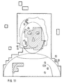
- FIG. 11 shows the vector mask (outer contours hatched) and the DCT mask (area hatched) for a moving image template. As can be seen from FIG. 11, only strongly moving areas in the face and shoulder area have to be transmitted by means of DCT.
- a gradient method in particular in accordance with EP 236 519 A1, which requires three iteration steps, can be used for the motion estimator ME.
- the same block from the previous vector field is used as the starting value for the estimate.
- Non-integer vectors can be interpolated bilinearly.
- a complete picture can be described by 396 vectors.
- the FIR (finite impulse response) filter structures also known from EP 236 519 A1 can be used as the extrapolation filter MCFE.
- a planar interpolation of non-integer vectors is possible with such filters as follows: Luminance: 2x oversampling with seven coefficients Chrominance: 4x oversampling with eleven coefficients.
- the same DCT algorithm is used for all operating modes.
- the DCT encoder achieves an average data rate of ⁇ 1 bit / pixel.
- a two-dimensional DCT transformation of 8 * 8 pixels is achieved by two successive one-dimensional DCT transformations of eight pixels each.
- the same algorithm is used for back and forth transformation.
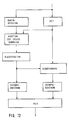
- An overview of the entire DCT coding is given in FIG. 12, which is described in detail in DE 37 09 094.1. Here is just a brief explanation of the function blocks according to FIG. 12:
- Edge detection achieves a local adaptation of the spectral visibility thresholds. If diagonal edges are detected in a block, coefficients are also taken into account that only half their visibility threshold.
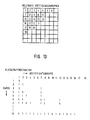
- the coefficients that exceed the visibility threshold are divided into classes and transferred ( Figure 13).
- the class specifies which coefficients are transmitted in which order (coefficient addressing).
- the class information is transmitted entropy-coded as additional information.
- the coefficients can be combined directly into classes (e.g. 8 classes with a maximum of 7 coefficients).
- the particularly common values of the AC and DC coefficients are optimally coded, the rarely occurring values are coded with a prefix Postfix binary code.
Landscapes
- Engineering & Computer Science (AREA)
- Multimedia (AREA)
- Signal Processing (AREA)
- Compression Or Coding Systems Of Tv Signals (AREA)
- Compression, Expansion, Code Conversion, And Decoders (AREA)
Description
Die Erfindung betrifft ein Verfahren zur senderseitigen Aufbereitung einer Bildsequenz für die Übertragung über einen Kanal mit begrenzter Datenkapazität und deren empfangsseitige Rekonstruktion.The invention relates to a method for processing an image sequence on the transmitter side for transmission over a channel with limited data capacity and reconstructing it on the receiving side.
Für Bildinformationen, die über einen Übertragungskanal mit begrenzter Datenkapazität übertragen werden sollen, gibt es zahlreiche Verfahren zur Redundanz- und Irrelevanzverminderung. In Esprit '86 Results and Achievements, Commission of the European Communities, Directorate General XIII, 1987, North-Holland, Seiten 413 bis 422, werden einige solcher Verfahren vorgeschlagen. Beim DPCM (Differential Pulse Code Modulation)-Verfahren wird anstelle aktueller Abtastwerte die Differenz zwischen dem aktuellen Wert und einem Prädiktionswert übertragen. Die Datenkompression wird durch Quantisierung erreicht. Bei der adaptiven DPCM wird anhand eines Bewegungskriteriums die Prädiktion und der Quantisierungsgrad gesteuert. Beim ABTC (Adaptive Block Truncation Coding)-Verfahren wird die Codierung je nach Bewegungsanteil von Bildbereichen in 3 Moden gesteuert. Das HPC (Hierarchical Predictive Coding)-Verfahren basiert auf der Kombination von Prädiktionscodierung und Interpolation. Bei der Transformationscodierung, z.B. der ADCT (Adaptive Cosine Transform)-Codierung werden die örtlichen Abtastwerte eines Bildblocks mittels einer mathematischen Vereinbarung transformiert zur Gewinnung von entkorrelierten Koeffizienten. Die Datenkompression wird durch Abschneiden vom Koeffizienten und nichtlinearer Quantisierung erreicht. Bei der Vektorquantisierung wird das Bild in eine große Zahl kleiner Zellen unterteilt, z.B. 2x2 oder 4x4 Bildelemente. Jede Zelle von K Bildelementen wird dann als Vektor im K dimensionalen Raum aufgefaßt. Eine Anzahl von repräsentativen Vektoren wird für die Übertragung ausgewählt. Für die Codierung werden die aktuellen Bildvektoren durch die repräsentativen Vektoren in ihrer Nachbarschaft beschrieben.There are numerous methods for reducing redundancy and irrelevance for image information that is to be transmitted via a transmission channel with limited data capacity. Some such methods are proposed in Esprit '86 Results and Achievements, Commission of the European Communities, Directorate General XIII, 1987, North Holland, pages 413 to 422. In the DPCM (Differential Pulse Code Modulation) method, the difference between the current value and a prediction value is transmitted instead of the current sample values. Data compression is achieved through quantization. With the adaptive DPCM, the prediction and the degree of quantization are controlled using a movement criterion. With the ABTC (Adaptive Block Truncation Coding) method, the coding is controlled in three modes depending on the movement share of image areas. The HPC (Hierarchical Predictive Coding) method is based on the combination of prediction coding and interpolation. In the case of the transformation coding, for example the ADCT (Adaptive Cosine Transform) coding, the local sample values of an image block are transformed by means of a mathematical agreement in order to obtain uncorrelated coefficients. Data compression is achieved by truncating the coefficient and nonlinear quantization. In vector quantization, the image is turned into a large number divided into small cells, e.g. 2x2 or 4x4 picture elements. Each cell of K picture elements is then interpreted as a vector in K dimensional space. A number of representative vectors are selected for transmission. For coding, the current image vectors are described by the representative vectors in their neighborhood.
Aus der DE-C-37 04 777 ist es bekannt, die Bewegungsvektoren für Teilbildbereiche zu ermitteln und diese zu codieren. Bei stark bewegten Bereichen werden bildpunktabhängige Informationen für diese Teilbildbereiche übertragen.From DE-C-37 04 777 it is known to determine the motion vectors for partial image areas and to code them. In the case of strongly moving areas, pixel-dependent information is transmitted for these partial picture areas.
Aus SPIE (International Society for Optical Engineering), Band 594 : Image Coding, Seiten 119 bis 128, ist es bekannt, für ein ganzes sich bewegendes Objekt Verschiebungsvektoren zu ermitteln und zu übertragen. Prädiktionsfehler werden blockweise codiert, beispielsweise mittels einer DCT (discrete cosine transform)-Transformation und übertragen. Ausgelassene Zwischenbilder werden empfangsseitig bewegungsadaptiv interpoliert.From SPIE (International Society for Optical Engineering), volume 594: Image Coding, pages 119 to 128, it is known to determine and transmit displacement vectors for an entire moving object. Prediction errors are coded in blocks, for example by means of a DCT (discrete cosine transform) transformation and transmitted. Omitted intermediate images are interpolated on the receiving side in a motion-adaptive manner.
Aus "Motion Compensated Vector Quantization", Proceedings of the ICASSP, Seiten 989 bis 992, Tokyo, 07. bis 11. April 1986 ist ein Verfahren zur senderseitigen Aufbereitung einer Bildsequenz nach einer Bildaufbauphase für die Übertragung über einen Kanal mit begrenzter Datenkapazität und deren empfangsseitige Rekonstruktion bekannt. Es erfolgt dort ein teilbildbereichsweises Ermitteln und Übertragen von Verschiebungsvektoren. Zur Entscheidung, welche Verschiebungsvektoren zu übertragen sind, werden Bildpunktdifferenzen zwischen dem aktuellen Bild und einem zeitlich davorliegenden Bild ermittelt. Wenn die Summe der Bildpunktdifferenzen einen Schwellwert überschreitet, wird die vektorquantisierte Version dieses Teilbildbereiches übertragen, ansonsten nur die Komponenten des Verschiebungsvektors.From "Motion Compensated Vector Quantization", Proceedings of the ICASSP, pages 989 to 992, Tokyo, April 7 to 11, 1986, a method for the transmitter-side preparation of an image sequence after an image construction phase for transmission over a channel with limited data capacity and its reception side Reconstruction known. There is a partial image area-by-area determination and transmission of displacement vectors. To decide which displacement vectors are to be transmitted, pixel differences between the current image and a previous image are determined. If the sum of the pixel differences exceeds a threshold value, the vector-quantized version of this partial image area becomes transmitted, otherwise only the components of the displacement vector.
Aus "Digital Video Transmission and Coding for the Broadband ISDN", IEEE Transactions on Consumer Electronics, Seiten 16 bis 35, Vol. 34, New York, Februar 1988 ist es bekannt, Verschiebungsvektoren für wenig bewegte Teilbildbereiche zu ermitteln und stark bewegte Teilbildbereiche durch quantisierte Koeffizienten zu beschreiben. Die durch Unterabtastung ausgelassenen Bildpunkte werden interpoliert bzw. extrapoliert. Es werden dort aber keine komplett ausgelassenen Bilder rekonstruiert.From "Digital Video Transmission and Coding for the Broadband ISDN", IEEE Transactions on Consumer Electronics,
Aufgabe der Erfindung ist es, ausgehend vom Oberbegriff des Patentanspruchs 1, ein anderes Verfahren anzugeben, welches insbesondere eine gute empfangsseitige Bildrekonstruktion ermöglicht. Diese Aufgabe wird durch die Merkmale des Patentanspruchs 1 gelöst. Die Unteransprüche zeigen vorteilhafte Weiterbildungen dieses Verfahrens auf.It is the object of the invention, starting from the preamble of
Die Erfindung weist folgende Vorteile auf:
Es wird eine hohe Bildqualität erreicht, was insbesondere durch die Ermittlung eines bewegungskompensierten Schätzbildes und der aktivitätsgesteuerten Codierung von Teilbildbereichen ermöglicht wird.The invention has the following advantages:
A high image quality is achieved, which is made possible in particular by determining a motion-compensated estimated image and the activity-controlled coding of partial image areas.
Durch eine bewegungskompensierte empfängerseitige Bildextra-(-inter)-polation wird eine ruckartige Bilddarstellung vermieden. Der Übertragungskanal wird optimal ausgenutzt. Im Gegensatz zur Realisierung gemäß SPIE, Band 594, Seiten 119 bis 128, wo ein ganzes Objekt durch einen Verschiebungsvektor beschrieben wird und demnach in den Randbereichen dieses Objekts ein großer Unsicherheitsbereich entsteht, der nur durch Übertragung von Prädiktionsfehlern im gesamten Unsicherheitsbereich klein gehalten werden kann, muß beim Verfahren nach der Erfindung nur bei ganz wenigen Teilbildbereichen/Blöcken Originalbildinhalt bzw. Prädiktionsfehler übertragen werden. Durch die Auswahl der zu übertragenden transformierten Teilbildbereiche/Blöcke anhand der Differenzen (Fehler) zu vorhergehenden Teilbildbereichen /Blöcken läßt sich bereits mit wenig Übertragungsdaten ein bezüglich eines Bewegungsablaufes sicheres Bild rekonstruieren. Das Verfahren nach der Erfindung bzw. ein danach ausgeführter Codec erlaubt folgende Betriebsarten:
- Übertragung der Kopf-Schulterdarstellung einer Person mit einer zeitlichen Auflösung von 25 (30) Bildern pro Sekunde,
- Übertragung von Standbildern mit hoher Ortsauflösung und daraus abgeleitet:
- Standbild mit eingefrorenem Bewegtbild,
- Standbild mit eingeblendetem Bewegtbild.
- Transmission of the head-shoulder representation of a person with a temporal resolution of 25 (30) frames per second,
- Transfer of still images with high spatial resolution and derived from it:
- Still picture with frozen moving picture,
- Still picture with superimposed moving picture.
Anhand der Zeichnungen wird ein Ausführungsbeispiel der Erfindung nun näher erläutert. Es zeigen:
- Fig. 1
- ein Blockschaltbild für ein Bildtelefon über ISDN, bei welchem das Verfahren nach der Erfindung eingesetzt wird,
- Fig. 2
- das Prinzip der bewegungskompensierten Prädiktion,
- Fig. 3
- das Prinzip der blockorientierten Bildextrapolation,
- Fig. 4
- ein Video-Coder mit Codierung der Quellbildsequenz,
- Fig. 5
- ein Video-Coder mit Codierung des Prädiktionsfehlers,
- Fig. 6
- eine Bitmaske zur Adressierung der Verschiebungsvektoren,
- Fig. 7
- eine Kennlinie zur Dämpfung kleiner Differenzen,
- Fig. 8
- eine Sortiertabelle für die DFD,
- Fig. 9
- ein Video-Decoder,
- Fig. 10
- einen Datenrahmen für die Übertragung,
- Fig. 11
- die Vektor- und DCT-Maske bei einer Bildvorlage mit Bewegungsanteil,
- Fig. 12
- eine Übersicht über die DCT-Codierung,
- Fig. 13
- die DCT-Klassifikation.
- Fig. 1
- 2 shows a block diagram for a videophone over ISDN, in which the method according to the invention is used,
- Fig. 2
- the principle of motion-compensated prediction,
- Fig. 3
- the principle of block-oriented image extrapolation,
- Fig. 4
- a video encoder with coding of the source image sequence,
- Fig. 5
- a video encoder with coding of the prediction error,
- Fig. 6
- a bit mask for addressing the displacement vectors,
- Fig. 7
- a characteristic curve for damping small differences,
- Fig. 8
- a sorting table for the DFD,
- Fig. 9
- a video decoder,
- Fig. 10
- a data frame for transmission,
- Fig. 11
- the vector and DCT mask for an image template with a movement component,
- Fig. 12
- an overview of the DCT coding,
- Fig. 13
- the DCT classification.
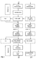
Das Bildtelefon nach Fig. 1 besteht aus getrennten Codern und Decodern für die Bild- und Tonübertragung. Damit ist z.B. eine Übertragung über 2 B-Kanäle in einem ISDN-Netz möglich. Eine Übertragung von Bild und Ton über einen B-Kanal ist nach geeigneter Quellcodierung des Tones ebenfalls möglich, ohne daß sich am Prinzip der Bildcodierung etwas ändert. Die Eingangsbildsequenz R,G,B wird z.B. nach der digitalen Fernsehnorm CCIR 601 abgetastet (A/D-Wandlung und Taktableitung). Die Toninformation wird ebenfalls A/D gewandelt und einer Kompandierung unterworfen. Die Digitalabtastung erfolgt gemäß CCIR 601 folgendermaßen:
Die hohe Qualität dieser Abtastung erlaubt die Speicherung hochauflösender Standbilder, wie sie für die vorgenannte zweite Betriebsart vorgesehen ist.The high quality of this scan allows high-resolution still images to be stored, as is intended for the aforementioned second operating mode.
Zur Anpassung dieser Quellbildsequenz an den nachfolgenden Video-Coder wird diese folgendermaßen vorbehandelt (Preprocessing):
Halbieren der Auflösung des Bildes in horizontaler und vertikaler Richtung.To adapt this source image sequence to the following video coder, it is pre-treated as follows (preprocessing):
Halve the resolution of the image in the horizontal and vertical directions.
Reduktion der Chrominanzauflösung in vertikaler Richtung auf 1/2.Reduction of chrominance resolution in the vertical direction to 1/2.
Nutzung der Austastlücke zur Übertragung.Use the blanking interval for transmission.
Somit 352 * 288 aktive Bildpunkte; 25 Hz Bildwechsel.
Diese Maßnahme reduziert die Quelldatenrate von 216 Mbit/s auf 30.41 (36.49) MBit/s. Die weitere Reduzierung geschieht im Video-Coder, der in Fig. 4 bzw. Fig. 5 dargestellt ist. Mit sender- und empfängerseitigen ISDN-Interface Schaltungen wird die Übertragung auf 64 kBit/s ISDN-Kanälen ermöglicht. Empfängerseitig erfolgt eine zur senderseitigen Aufbereitung entsprechende Decodierung. Die Figur 9 zeigt den entsprechenden Video-Decoder. Eine Signalnachverarbeitung (Post-Processing) stellt wieder ein gemäß CCIR 601 normgerechtes Bildformat her, welches nach D/A-Wandlung und Hinzufügung von Synchroninformation zur Wiedergabe auf einem RGB-Monitor geeignet ist. Die Schaltungsblöcke FECC (Forward Error Correction Control) und ECC (Error Correction Control) sind Einheiten zur bedarfsweisen Fehlerkorrektur. Übertragungsfehler können damit erkannt und soweit möglich korrigiert werden.This measure reduces the source data rate from 216 Mbit / s to 30.41 (36.49) Mbit / s. The further reduction takes place in the video coder, which is shown in FIGS. 4 and 5. The transmission on 64 kbit / s ISDN channels is made possible with transmitter and receiver side ISDN interface circuits. On the receiver side there is a decoding corresponding to the processing on the transmitter side. Figure 9 shows the corresponding video decoder. Signal post-processing again produces an image format that conforms to the CCIR 601 standard and which is based on D / A conversion and The addition of synchronous information is suitable for playback on an RGB monitor. The FECC (Forward Error Correction Control) and ECC (Error Correction Control) circuit blocks are units for correcting errors as required. Transmission errors can be recognized and corrected as far as possible.
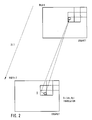
Die Grundidee des Codecs wird nun anhand der Figuren 2 und 3 erläutert. Sie besteht darin, nach dem Bildaufbau nur jedes 3. Bild (Fig. 2) zu codieren. Hierzu wird von dem Bild K+3 im Coder ein bewegungskompensiertes Schätzbild K+3* aus Bild K gebildet. Die Vektoren, mit denen K+3* gebildet wird, werden übertragen, so daß der Decoder das gleiche Schätzbild erzeugen kann. Es werden dann die Pixel zu Pixel Differenzen DFD zwischen dem Schätzbild K+3* und dem neuen Bild K+3 blockweise addiert (DFD = Displaced Frame Difference). Die DFD innerhalb eines BlockS/Teilbildbereichs von 8*8 Pixel ergibt sich zu
![]()
mit Blockkoordinaten: x=1,8 y=1,8
und Pixelintensität p.The basic idea of the codec is now explained with reference to FIGS. 2 and 3. It consists of coding only every third image (FIG. 2) after the image structure. For this purpose, the image K + 3 in the coder forms a motion-compensated estimation image K + 3 * from image K. The vectors with which K + 3 * is formed are transmitted so that the decoder can generate the same estimation picture. The pixels are then added in blocks to pixel differences DFD between the estimated image K + 3 * and the new image K + 3 (DFD = Displaced Frame Difference). The DFD within a block / field area of 8 * 8 pixels results in
![]()
with block coordinates: x = 1.8 y = 1.8
and pixel intensity p.
Für die Teilbildbereiche/Blöcke mit großen Summen, die Stellen mit großen Abweichungen kennzeichnen, wird entweder der Originalbildinhalt (Fig. 4) oder das Differenzbild (Fig. 5) mit einer wahrnehmungsadaptiven DCT (Discrete Cosine Transform) codiert. Im Empfänger wird die inverse DCT gebildet und in das bewegungskompensierte Schätzbild eingesetzt. Die fehlenden Zwischenbilder werden mit den übertragenen Verschiebungsvektoren D bewegungskompensiert extrapoliert oder interpoliert, so daß wieder ein weicher Bewegungsablauf entsteht (Fig. 3). Wie aus Fig. 3 ersichtlich ist, wird das Bild K+1 aus dem Bild K extrapoliert (Verschiebungsvektor + 1/3 DK) und das Bild K+2 aus dem Bild K+3 (Verschiebungsvektor - 1/3 DK+3).For the sub-picture areas / blocks with large sums, which mark locations with large deviations, either the original picture content (FIG. 4) or the difference picture (FIG. 5) is coded with a perceptually adaptive DCT (Discrete Cosine Transform). The inverse DCT is formed in the receiver and inserted into the motion-compensated estimation image. The missing intermediate images are extrapolated or interpolated with the transmitted displacement vectors D in a motion-compensated manner, so that a softer one again Movement sequence arises (Fig. 3). As can be seen from FIG. 3, the image K + 1 is extrapolated from the image K (
Um einen schnellen Bildaufbau am Anfang der Verbindung zu gewährleisten, wird zuerst ein um den Faktor 4 planar tiefpassgefiltertes erstes Bild übertragen. Danach wird der Bildinhalt ergänzt, der um den Faktor 2 planar tiefpassgefiltert ist. Schließlich wird ungefilterter Bildinhalt ergänzt. Das Maß zur Steuerung dieser drei Betriebsarten wird aus der mittleren DFD - MDFD - gewonnen. Das Verfahren garantiert, daß der Bildinhalt auch bei großen Änderungen konsistent bleibt. D.h. ein willkürliches "Einfrieren" von Bildinhalten bei großen Änderungen wird vermieden. Zur Ermittlung dieser mittleren DFD werden die Bildpunkt-zu-Bildpunkt-Differenzen aller Blöcke zu je 8*8 Pixel herangezogen. Es ergibt sich demnach:
![]()
i=1,44
j=1,36
Die Funktion des Video-Coders wird am Beispiel der Luminanzbildverarbeitung (Fig. 4 und Fig. 5) beschrieben, da in der Chrominanzbildverarbeitung Ergebnisse aus dem Luminanzzweig übernommen werden. Beim Video-Coder nach Fig. 4 wird die Quellbildsequenz DCT transformiert, wohingegen beim Video-Coder nach Fig. 5 ein Differenzbild DCT transformiert wird. Da der Aufbau dieser beiden Video-Coder-Versionen sehr ähnlich ist, wird nur eine Ausführungsform ausführlich erläutert und für die andere nur die davon abweichende Realisierung beschrieben.In order to ensure a quick image build-up at the beginning of the connection, a first image that is low pass-filtered by a factor of 4 is first transmitted. Then the image content is supplemented, which is low pass filtered by a factor of 2 planar. Finally, unfiltered image content is added. The measure for controlling these three operating modes is obtained from the middle DFD - MDFD. The process guarantees that the image content remains consistent even with large changes. That is, an arbitrary "freezing" of image content with large changes is avoided. To determine this mean DFD, the pixel-to-pixel differences of all blocks of 8 * 8 pixels are used. The result is:
![]()
i = 1.44
j = 1.36
The function of the video encoder is described using the example of the luminance image processing (FIGS. 4 and 5), since results from the luminance branch are taken over in the chrominance image processing. The source image sequence DCT is transformed in the video encoder according to FIG. 4, whereas a difference image DCT is transformed in the video encoder according to FIG. 5. Since the structure of these two video coder versions is very similar, only one embodiment is explained in detail and for the other only the implementation which differs from this is described.
Jedes dem Eingang des Video-Coders als Y-PCM Signal zugeführte neue Bild K+3 wird mehrfach weiterverarbeitet:
- a) Das Bild K+3 wird in der Stufe TP1
um den Faktor 2 planar tiefpassgefiltert und die Abtastfrequenz halbiert. Am Ausgang erscheint ein Bild (K+3)′. Dieser, in der Ortsauflösung reduzierte Bildinhalt, wird verwendet, wenn die mittlere DFD einen Grenzwert TH2 überschreitet (Spatiales Subsampling bei großen Änderungen). Die Verkleinerung wird im Decoder und für die Prädiktion durch Interpolation wieder aufgehoben (Stufe TP3). - b) Das Bild K+3′ wird in der Stufe TP2 noch einmal um
den Faktor 2 planar tiefpassgefiltert und die Abtastfrequenz halbiert. Am Ausgang der Stufe TP2 erscheint das Bild (K+3)''. Dieses Bild wird im Falle des Verbindungsaufbaus oder eines Schnitts verwendet und vollständig mit Hilfe der DCT übertragen. Als Kriterium hierfür wird ebenfalls die mittlere DFD (wie in a), jedoch mit einer Schwelle TH4 > TH2 herangezogen. Damit erhält man einen schnellen Bildaufbau. Die Verkleinerung wird im Decoder und für die Prädiktion durch Interpolation wieder aufgehoben (Stufen TP3 und TP4). - c) Mit Hilfe des in einem Bildspeicher FST2 gespeicherten Bildes K′ und dem Bild K+3′ wird im Bewegungsvektorschätzer ME ein Satz von Verschiebungsvektoren D ermittelt. Ein Vektor gilt für einen
Bereich von 16*16 Pixel. - d) Das Bild K+3 wird mit dem im Bildspeicher FST1 gespeicherten Bild K verglichen. Das Bild K wird durch eine inverse DCT-Transformation DCT⁻¹ und gegebenenfalls Aufhebung der Tiefpassfilterung (Stufen TP3, TP4) erstellt. Mit Hilfe der Frame-Differenz-Stufe FD werden dabei blockweise geänderte Bildbereiche von ungeänderten unterschieden. Die Bildung der Frame-Differenz geschieht nach der Beziehung:

x=1,8
y=1,8
- a) The image K + 3 is planar low-pass filtered by a factor of 2 in stage TP1 and the sampling frequency is halved. An image (K + 3) 'appears at the exit. This image content, which is reduced in spatial resolution, is used when the average DFD exceeds a limit value TH2 (spatial subsampling for large changes). The reduction is canceled in the decoder and for the prediction by interpolation (level TP3).
- b) The image K + 3 'is again low pass filtered by a factor of 2 in the stage TP2 and the sampling frequency halved. The image (K + 3) '' appears at the exit of stage TP2. This image is used in the event of a connection or a cut and is transmitted entirely using the DCT. The average DFD (as in a), but with a threshold TH4> TH2, is also used as a criterion for this. This gives you a quick image build-up. The reduction is canceled in the decoder and for the prediction by interpolation (levels TP3 and TP4).
- c) With the help of the image K 'stored in an image memory FST2 and the image K + 3', a set of displacement vectors D is determined in the motion vector estimator ME. A vector applies to an area of 16 * 16 pixels.
- d) The image K + 3 is compared with the image K stored in the image memory FST1. The image K is created by an inverse DCT transformation DCT⁻¹ and, if necessary, cancellation of the low-pass filtering (stages TP3, TP4). With the help of the frame difference level FD, image areas changed in blocks are distinguished from unchanged ones. The frame difference is formed after the relationship:
x = 1.8
y = 1.8
Alle diese Informationen werden durch die Steuerung CONTROL zu einem Übertragungssignal aufbereitet. Diese Informationen werden aus der DCT-Codierung des DFD-Bildes (Prädiktionsfehler Fig. 5) oder des Quellbildes (Fig. 4) gewonnen. Die freie Kanalbitrate wird zur Übertragung von DCT-Blöcken genutzt. Dabei werden die Blöcke mit der größten DFD übertragen, bis der Kanal ausgefüllt ist. Die Bitmaske zur Adressierung der DCT-Blöcke wird VWL codiert (Fig. 6).All of this information is processed into a transmission signal by the CONTROL controller. This information is obtained from the DCT coding of the DFD image (prediction error FIG. 5) or the source image (FIG. 4). The free channel bit rate is used for the transmission of DCT blocks. The blocks with the largest DFD are transmitted until the channel is filled. The bit mask for addressing the DCT blocks is coded VWL (Fig. 6).
Für die Prädiktion wird im Coder die inverse DCT-Transformation DCT⁻¹ gebildet. Ferner befinden sich hier Interpolationsfilter, die verkleinerten Bildinhalt wieder vergrößern (TP3 und TP4). Im Bildspeicher FST1 wird das rekonstruierte Bild K gespeichert. Den Daten können als Übertragungsfehlerschutz zusätzlich Informationen eines FEC-Codes (FEC = Forward error correction) beigefügt werden. Die Steuerung (Control) überwacht alle Funktionen des Codecs und schaltet es gemäß den Randbedingungen in die entsprechende Betriebsart. Die ISDN-Schnittstelle verbindet das Codec mit dem Netz. Die Auswahl der zu übertragenden Bildinformation wird durch Multiplexer MUX gesteuert, die wiederum von der Steuerung (Control) ihre Umschaltbefehle erhalten.The inverse DCT transformation DCTT¹ is formed in the coder for the prediction. There are also interpolation filters here that enlarge the reduced image content again (TP3 and TP4). The reconstructed image K is stored in the image memory FST1. Information on a FEC code (FEC = Forward Error Correction) can also be added to the data as transmission error protection. The control monitors all functions of the codec and switches it to the corresponding operating mode according to the boundary conditions. The ISDN interface connects the codec to the network. The selection of the image information to be transmitted is controlled by multiplexers MUX, which in turn receive their switching commands from the control system.
In Abweichung zur Realisierung gemäß Fig. 4 wird in Fig. 5 nicht das Bild K+3 über den Multiplexer MUX zur DCT-Transformationsstufe geführt, sondern die Differenz zwischen dem Bild K+3 und dem Schätzbild K+3* (Stufe Σ 1). Hierdurch werden nur die Prädiktionsfehler DCT transformiert. Der 'Noise Limier' NL ist hier vor den Eingang des Multiplexers MUX geschaltet. Um für die Prädiktion wieder ein Quellbild zur Verfügung zu haben, muß die Differenzbildung nach der DCT-Rücktransformation DCT⁻¹ wieder rückgängig gemacht werden (Stufe Σ 2).In contrast to the realization according to FIG. 4, in FIG. 5 the image K + 3 is not led to the DCT transformation stage via the multiplexer MUX, but the difference between the image K + 3 and the estimation image K + 3 * (stage Σ 1) . As a result, only the prediction errors DCT are transformed. The 'Noise Limier' NL is connected in front of the input of the MUX multiplexer. In order to have a source image again for the prediction, the difference formation after the DCT inverse transformation DCT⁻¹ must be undone again (level Σ 2).
Im Video-Decoder (Fig. 9) - nur der Luminanzteil ist dargestellt - werden nach der ISDN-Schnittstelle die Steuerinformationen aus dem Datenstrom gewonnen (SYNC, CONTROL'). Die optionale Fehlerkorrektur EC erkennt Übertragungsfehler und korrigiert sie soweit möglich. der Demultiplexer DEMUX trennt Verschiebungsvektoren, DCT-Koeffizienten und den Chrominanzanteil. Die Verschiebungsvektoren werden gespeichert, die Bitmasken werden decodiert. Mit Hilfe der decodierten Vektoren D′ und dem im Bildspeicher FST gespeicherten Bild K wird mit Hilfe des Extrapolators zur Bewegungskompensation MCFE1 ein bewegungskompensiertes Schätzbild K+3* des aktuellen Bildes gebildet. Die übertragenen Bildblöcke aus dem Bild K+3 werden einer inversen DCT-Transformation DCT⁻¹ unterworfen und in das Schätzbild K+3* mittels der Summierstufe Σ 3 eingesetzt. Ein weiterer Extrapolator zur Bewegungskompensation MCFE2 extrapoliert die ausgelassenen Bilder K+1 und K+2 gemäß Fig. 3 bewegungskompensiert.In the video decoder (FIG. 9) - only the luminance part is shown - the control information is obtained from the data stream after the ISDN interface (SYNC, CONTROL '). The optional EC error correction detects transmission errors and corrects them as far as possible. the demultiplexer DEMUX separates displacement vectors, DCT coefficients and the chrominance component. The shift vectors are stored, the bit masks are decoded. With the help of the decoded vectors D 'and the image K stored in the image memory FST, a motion-compensated estimation image K + 3 * of the current image is formed with the aid of the extrapolator for motion compensation MCFE1. The transmitted image blocks from image K + 3 are subjected to an inverse DCT transformation DCT⁻¹ and inserted into the estimation image K + 3 * by means of summing
Nach Fig. 3 wird das Bild K+1 aus Bild K durch Umrechnen der Vektoren, die zu Bild K geführt haben, extrapoliert. Bild K+2 wird aus Bild K+3 durch Umrechnen der Vektoren, die zu Bild K+3 geführt haben, extrapoliert. Auf diese Weise wird die Originalbildfrequenz von 25 (30) Bildern/s wiederhergestellt. Das Bildsignal kann mit einem rekursiven zeitlichen Filter von kleinen Bewegungsdefekten befreit werden (nicht dargestellt).According to FIG. 3, the image K + 1 is extrapolated from image K by converting the vectors which have led to image K. Image K + 2 is extrapolated from image K + 3 by converting the vectors that led to
Der Wert eines Pixels p(x,y) berechnet sich dabei nach der Formel:
![]()
The value of a pixel p (x, y) is calculated using the formula:
![]()
Schnelle Änderungen werden so auf mehrere Bilder verzögert; es entsteht ein Überblendeffekt, der sich z.B. bei Augen und Mundbewegungen, die nicht durch Vektoren beschreibbar sind, vorteilhaft auswirkt.Fast changes are thus delayed to several pictures; there is a cross-fading effect, which has an advantageous effect, for example, on eyes and mouth movements that cannot be described by vectors.
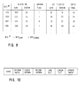
Figur 10 zeigt einen Datenrahmen für die Übertragung. Die Daten werden seriell in sieben verschiedenen Zeitschlitzen übertragen: Synchronwort (Sync.), Vektor Maske (Vector Mask.), Steuerinformation (Contr. Inform.), Vektorinformation (Vector. Inform.), Luminanz- und Chrominanz-DCT (Lum. DCT, Chrom. DCT) und Aktualisierungsinformation (Update Mask).Figure 10 shows a data frame for transmission. The data is transmitted serially in seven different time slots: synchronous word (Sync.), Vector mask (Vector Mask.), Control information (Contr. Inform.), Vector information (Vector. Inform.), Luminance and chrominance DCT (Lum. DCT , Chrome. DCT) and Update Mask.
In Figur 11 ist die Vektormaske (Außenkonturen schraffiert) und die DCT-Maske (flächig schraffiert) für eine bewegte Bildvorlage dargestellt. Wie aus Figur 11 ersichtlich, müssen nur stark bewegte Bereiche im Gesichts- und Schulterbereich mittels DCT übertragen werden.FIG. 11 shows the vector mask (outer contours hatched) and the DCT mask (area hatched) for a moving image template. As can be seen from FIG. 11, only strongly moving areas in the face and shoulder area have to be transmitted by means of DCT.
Für den Bewegungsschätzer ME kann ein Gradientenverfahren insbesondere gemäß EP 236 519 A1 verwendet werden, welches mit drei Iterationsschritten auskommt. Als Startwert der Schätzung wird vom ortsgleichen Block aus dem vorhergehenden Vektorfeld ausgegangen. Nichtganzzahlige Vektoren können bilinear interpoliert werden. Ein vollständiges Bild kann durch 396 Vektoren beschrieben werden.A gradient method, in particular in accordance with EP 236 519 A1, which requires three iteration steps, can be used for the motion estimator ME. The same block from the previous vector field is used as the starting value for the estimate. Non-integer vectors can be interpolated bilinearly. A complete picture can be described by 396 vectors.
Als Extrapolationsfilter MCFE können die ebenfalls aus EP 236 519 A1 bekannten FIR (finite impulse response)-Filterstrukturen benutzt werden. Eine planare Interpolation nichtganzzahliger Vektoren ist mit solchen Filtern folgendermaßen möglich:
Luminanz: 2fach-Überabtastung mit sieben Koeffizienten
Chrominanz: 4fach-Überabtastung mit elf Koeffizienten.The FIR (finite impulse response) filter structures also known from EP 236 519 A1 can be used as the extrapolation filter MCFE. A planar interpolation of non-integer vectors is possible with such filters as follows:
Luminance: 2x oversampling with seven coefficients
Chrominance: 4x oversampling with eleven coefficients.
Für die DCT-Transformation wird wie bereits geschildert eine feste Blockgröße von 8*8 Bildpunkten verwendet. Je nach Betriebszustand verarbeitet die DCT Bildblöcke von 8*8 Bildpunkten
- * in voller Auflösung (normaler Mode) nach Tabelle 1 (Figur 8) oder
- * mit halber Auflösung in beiden Richtungen bei drohendem Bufferüberlauf (entspricht einem
Bildausschnitt von 16*16 Punkten). - * mit einem viertel der Auflösung bei Bildaufbau und Szenenschnitt (entspricht einem
Bildausschnitt von 32*32 Punkten).
- * in full resolution (normal mode) according to Table 1 (Figure 8) or
- * with half resolution in both directions if there is a risk of buffer overflow (corresponds to an image section of 16 * 16 points).
- * with a quarter of the resolution for image composition and scene editing (corresponds to an image detail of 32 * 32 points).
Für alle Betriebsarten wird der gleiche DCT-Algorithmus verwendet. Der DCT-Coder erreicht eine mittlere Datenrate von < 1 bit/Bildpunkt.The same DCT algorithm is used for all operating modes. The DCT encoder achieves an average data rate of <1 bit / pixel.
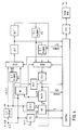
Eine zweidimensionale DCT-Transformation von 8*8 Bildpunkten wird durch zwei aufeinanderfolgende eindimensionale DCT-Transformationen von jeweils acht Bildpunkten erreicht. Für Hin- und Rücktransformation wird der gleiche Algorithmus verwendet. Eine Übersicht über die gesamte DCT-Codierung gibt Figur 12, die ausführlich in der DE 37 09 094.1 beschrieben ist. Hier nur eine Kurzerläuterung der Funktionsblöcke gemäß Figur 12:A two-dimensional DCT transformation of 8 * 8 pixels is achieved by two successive one-dimensional DCT transformations of eight pixels each. The same algorithm is used for back and forth transformation. An overview of the entire DCT coding is given in FIG. 12, which is described in detail in DE 37 09 094.1. Here is just a brief explanation of the function blocks according to FIG. 12:
Durch die Kantendetektion wird eine lokale Adaption der spektralen Sichtbarkeitsschwellen erreicht. Werden in einem Block diagonale Kanten detektiert, so werden auch Koeffizienten berücksichtigt, die ihre Sichtbarkeitsschwelle nur zur Hälfte erreichen.Edge detection achieves a local adaptation of the spectral visibility thresholds. If diagonal edges are detected in a block, coefficients are also taken into account that only half their visibility threshold.
Die Koeffizienten, die die Sichtbarkeitsschwelle überschreiten, werden nach Klassen eingeteilt und übertragen (Figur 13). Die Klasse gibt an, welche Koeffizienten in welcher Reihenfolge übertragen werden (Koeffizientenadressierung). Die Klasseninformation wird als Zusatzinformation entropiecodiert übertragen.The coefficients that exceed the visibility threshold are divided into classes and transferred (Figure 13). The class specifies which coefficients are transmitted in which order (coefficient addressing). The class information is transmitted entropy-coded as additional information.
- * Unterdrückung singulärer Koeffizienten.* Suppression of singular coefficients.
- * Relevante Koeffizientengruppen auswählen. Eine Koeffizientengruppe wird nur dann berücksichtigt, wenn mindestens die Hälfte ihrer Koeffizienten die Sichtbarkeitsschwelle überschreitet. Alle Koeffizienten einer relevanten Koeffizientengruppe werden übertragen (z.B. 18 Koeffizientengruppen).* Select relevant coefficient groups. A coefficient group is only considered if at least half of its coefficients exceed the visibility threshold. All coefficients of a relevant coefficient group are transmitted (e.g. 18 coefficient groups).
- * Alle relevanten Koeffizientengruppen werden zu einer Klasse zusammengefaßt, z.B. 16 Klassen (Figur 13).* All relevant coefficient groups are combined into one class, e.g. 16 classes (Figure 13).
Da hier nur wenige Koeffizienten übertragen werden müssen, können die Koeffizienten direkt zu Klassen zusammengefaßt werden (z.B. 8 Klassen bei max. 7 Koeffizienten).Since only a few coefficients have to be transmitted here, the coefficients can be combined directly into classes (e.g. 8 classes with a maximum of 7 coefficients).
Nur die durch die Klassifikation eines Blocks ausgewählten Koeffizienten werden quantisiert. Jeder Koeffizient wird entsprechend seiner Sichtbarkeitsschwelle quantisiert. Die Wahrnehmbarkeitsschwellen für die einzelnen Koeffizienten wurden durch visuelle Tests ermittelt.Only the coefficients selected by classifying a block are quantized. Each coefficient is quantized according to its visibility threshold. The perceptibility thresholds for the individual coefficients were determined by visual tests.
Die gesamte Daten- und Steuerinformation ist entropiecodiert:
- * Die selektierten und quantisierten AC(Wechselanteil)-Koeffizienten.
- * Der Prädiktionsfehler für die DC(Gleichanteil)-Koeffizienten.
- * Die Klasseninformation.
- * The selected and quantized AC (alternating component) coefficients.
- * The prediction error for the DC (DC component) coefficients.
- * The class information.
Die besonders häufigen Werte der AC- und DC-Koeffizienten sind optimal codiert, die selten vorkommenden Werte werden mit einem Präfix Postfix-Binär-Code codiert.The particularly common values of the AC and DC coefficients are optimally coded, the rarely occurring values are coded with a prefix Postfix binary code.
Folgende Variationen des Codec sind möglich:
- Einsatz einer anderen Transformationscodierung an Stelle von DCT.
- Einsatz einer Vektorquantisierung an Stelle der DCT. Bei höheren Bitraten auch DPCM.
- Bewegungsschätzer: Es kann an Stelle eines Gradientenschätzverfahrens auch ein Blockmatching Suchverfahren angewendet weden. (z.B. Hierarchische Blockmatching Displacementschätzverfahren nach EP-A-0 236 519.
- Im Decoder kann an Stelle der Extrapolation ausgelassener Bilder eine Interpolation erfolgen.
- Die zeitliche Tiefpaßfilterung der rekonstruierten Bilder ist sowohl mit Hilfe einer FIR-Struktur als auch mittels einer IIR (infinite impulse response) möglich.
- Use of a different transformation coding instead of DCT.
- Use of vector quantization instead of DCT. With higher bit rates also DPCM.
- Motion estimator: Instead of a gradient estimation method, a block matching search method can also be used. (eg hierarchical block matching displacement estimation method according to EP-A-0 236 519.
- Instead of extrapolating omitted images, an interpolation can take place in the decoder.
- The temporal low-pass filtering of the reconstructed images is possible both with the help of an FIR structure and with an IIR (infinite impulse response).
Claims (10)
- Method for the preparation of an image sequence at the transmitter end for the transmission by way of a channel with limited data capacity and its reconstruction at the reception end, characterised thereby, that the image sequence is treated in the following manner after an image synthesis phase:- at the transmitter end, data of the individual images of the image sequence are evaluated as following with the omission of at least two intermediate images:a) for each partial image region, ascertaining and transmitting of the displacement vectors for a movement-compensated estimated image (k+3*) from the image (k) before the last omitted intermediate images,b) forming the dot-to-dot differences (DFD) between the estimated image (k+3*) and the new image (k+3) corresponding to the estimated image,c) for each partial image region, adding up these dot-to-dot differences (DFD),d) coding and transmitting these partial image regions or differences between partial image regions, which follow one on the other in time, in the sense of a redundancy reduction, for which the adding-up delivers large values and- at the reception end,e) a decoding inverse to the decoding at the transmitter end is undertaken,f) the data obtained by the decoding are inserted into the movement-compensated estimated image set up at the reception end with the displacement vectors andg) each absent intermediate image is extrapolated or interpolated, compensated for movement, with the transmitted displacement vectors.
- Method according to claim 1, characterised thereby, that the image sequence at the transmitter end is preliminarily treated for data reduction in the following manner:a) reducing the image resolution in horizontal and vertical direction,b) reducing the chrominance resolution in vertical direction to at least half,c) subscanning of the luminance signal andand that the image sequence at the reception end is again prepared inversely to the preliminary treatment at the transmitter end.
subscanning of the chrominance signals, - Method according to claim 1 or 2, characterised thereby, that the gating gap is also drawn upon for transmission.
- Method according to one of the claims 1 to 3, characterised thereby, that the images at the transmitter end are scanned progessively, i.e. without interlacing.
- Method according to one of the claims 1 to 4, characterised thereby, that the coding of the partial image regions or differences of partial image regions takes place by a perception-adaptive transformation coding, for example a discrete cosine transformation.
- Method according to one of the claims 1 to 4, characterised thereby, that the coding of the partial image regions or differences of partial image regions takes place by a vector quantisation.
- Method according to one of the claims 1 to 4, characterised thereby, that the coding of the partial image regions or differences of partial image regions takes place by differential pulse code modulation.
- Method according to one of the claims 1 to 7, characterised thereby, that the displacement vectors are coded statistically for transmission as differences from the respectively preceding value, wherein only the first displacement vector for each image is transmitted as absolute value.
- Method according to one of the claims 1 to 8, characterised thereby, that for the transmission of differences of partial image regions, a weighting is undertaken in the sense that small differences are transmitted attenuated and large differences are transmitted unchanged.
- Method according to one of the claims 1 to 9, characterised thereby, that the image sequence reconstructed at the reception end is freed of jerky movement effects by means of a recursive temporal filter.
Applications Claiming Priority (2)
| Application Number | Priority Date | Filing Date | Title |
|---|---|---|---|
| DE3820038A DE3820038A1 (en) | 1988-06-13 | 1988-06-13 | METHOD FOR PROCESSING AND TRANSMITTING AN IMAGE SEQUENCE |
| DE3820038 | 1988-06-13 |
Publications (3)
| Publication Number | Publication Date |
|---|---|
| EP0346637A2 EP0346637A2 (en) | 1989-12-20 |
| EP0346637A3 EP0346637A3 (en) | 1991-03-20 |
| EP0346637B1 true EP0346637B1 (en) | 1994-04-06 |
Family
ID=6356419
Family Applications (1)
| Application Number | Title | Priority Date | Filing Date |
|---|---|---|---|
| EP89108917A Expired - Lifetime EP0346637B1 (en) | 1988-06-13 | 1989-05-18 | Method for processing and transmitting a picture sequence |
Country Status (2)
| Country | Link |
|---|---|
| EP (1) | EP0346637B1 (en) |
| DE (2) | DE3820038A1 (en) |
Families Citing this family (10)
| Publication number | Priority date | Publication date | Assignee | Title |
|---|---|---|---|---|
| NL9000424A (en) * | 1990-02-22 | 1991-09-16 | Philips Nv | TRANSFER SYSTEM FOR DIGITALIZED TELEVISION IMAGES. |
| US5305400A (en) * | 1990-12-05 | 1994-04-19 | Deutsche Itt Industries Gmbh | Method of encoding and decoding the video data of an image sequence |
| DE59108585D1 (en) * | 1990-12-05 | 1997-04-10 | Itt Ind Gmbh Deutsche | METHOD FOR CODING AND DECODING THE VIDEO DATA OF AN IMAGE SEQUENCE |
| KR0128860B1 (en) * | 1993-07-16 | 1998-04-10 | 배순훈 | Low Bit Rate Video Phone Coding System |
| US6061401A (en) * | 1995-03-20 | 2000-05-09 | Daewoo Electronics Co., Ltd. | Method and apparatus for selectively encoding/decoding a video signal |
| KR0181033B1 (en) * | 1995-03-20 | 1999-05-01 | 배순훈 | Apparatus for selectively encoding error signals |
| SE513353C2 (en) | 1998-10-21 | 2000-08-28 | Ericsson Telefon Ab L M | Partial image retrieval in the compressed domain |
| DE102004007184B3 (en) | 2004-02-13 | 2005-09-22 | Fraunhofer-Gesellschaft zur Förderung der angewandten Forschung e.V. | Method and apparatus for quantizing an information signal |
| DE102004007191B3 (en) | 2004-02-13 | 2005-09-01 | Fraunhofer-Gesellschaft zur Förderung der angewandten Forschung e.V. | Audio coding |
| DE102004007200B3 (en) | 2004-02-13 | 2005-08-11 | Fraunhofer-Gesellschaft zur Förderung der angewandten Forschung e.V. | Device for audio encoding has device for using filter to obtain scaled, filtered audio value, device for quantizing it to obtain block of quantized, scaled, filtered audio values and device for including information in coded signal |
Family Cites Families (2)
| Publication number | Priority date | Publication date | Assignee | Title |
|---|---|---|---|---|
| JPS61118085A (en) * | 1984-11-14 | 1986-06-05 | Nec Corp | Coding system and device for picture signal |
| US4727422A (en) * | 1985-06-03 | 1988-02-23 | Picturetel Corporation | Method and apparatus for efficiently communicating image sequence having improved motion compensation |
-
1988
- 1988-06-13 DE DE3820038A patent/DE3820038A1/en not_active Withdrawn
-
1989
- 1989-05-18 EP EP89108917A patent/EP0346637B1/en not_active Expired - Lifetime
- 1989-05-18 DE DE89108917T patent/DE58907382D1/en not_active Expired - Lifetime
Also Published As
| Publication number | Publication date |
|---|---|
| EP0346637A2 (en) | 1989-12-20 |
| DE58907382D1 (en) | 1994-05-11 |
| EP0346637A3 (en) | 1991-03-20 |
| DE3820038A1 (en) | 1989-12-14 |
Similar Documents
| Publication | Publication Date | Title |
|---|---|---|
| DE69120139T2 (en) | Device and method for the adaptive compression of successive blocks of a digital video signal | |
| DE69129595T2 (en) | Systems and methods for coding alternating fields in interlaced picture sequences | |
| DE69232063T2 (en) | Adaptive motion compensation with multiple motion compensators | |
| EP0359094B1 (en) | System for transmitting a picture signal with a high temporal and spatial resolution | |
| DE69323986T2 (en) | Image processing apparatus and method | |
| DE69323586T2 (en) | Layer encoding / decoding apparatus for a progressive input image signal | |
| DE69131438T2 (en) | Adaptive motion compensation for digital television | |
| DE69615948T2 (en) | Hierarchical image encoder and decoder | |
| DE69223560T2 (en) | Device for reducing quantization disturbances in an inter-frame hybrid coding system with motion compensation | |
| DE69620984T2 (en) | Noise estimation and noise reduction device for video signal processing | |
| DE3855648T2 (en) | METHOD AND DEVICE FOR HIERARCHIC CODING FOR THE EFFECTIVE TRANSMISSION OF IMAGE SEQUENCES | |
| DE69714071T2 (en) | DEVICE FOR COMPRESSING PIXEL BLOCKS IN AN IMAGE PROCESSING SYSTEM | |
| DE69221191T2 (en) | Method and device for predictive coding of an image signal with motion compensation | |
| DE69535228T2 (en) | Image conversion device | |
| DE69425919T2 (en) | Adaptive compression of digital video data | |
| DE69624669T2 (en) | Video encoder and decoder system and methods | |
| DE69328686T2 (en) | MOTION-COMPENSATED CANCELLATION OF THE INTERMEDIATE PROCESS WITH DIGITAL SUPPORT SIGNAL | |
| DE69123646T2 (en) | Coding method and device | |
| DE69312124T2 (en) | Video codec, in particular for a videophone | |
| EP0279053A1 (en) | Method for the transmission and reproduction of sequences of television pictures | |
| DE69222082T2 (en) | Encoding of video signals | |
| DE69125315T2 (en) | Coding method and coding device | |
| DE69428034T2 (en) | Image signal encoding and decoding | |
| DE69711736T2 (en) | Adaptive post filtering for a low bit rate video telephony system | |
| DE69227879T2 (en) | Still picture transmission system |
Legal Events
| Date | Code | Title | Description |
|---|---|---|---|
| PUAI | Public reference made under article 153(3) epc to a published international application that has entered the european phase |
Free format text: ORIGINAL CODE: 0009012 |
|
| AK | Designated contracting states |
Kind code of ref document: A2 Designated state(s): DE FR GB IT NL |
|
| PUAL | Search report despatched |
Free format text: ORIGINAL CODE: 0009013 |
|
| 17P | Request for examination filed |
Effective date: 19901228 |
|
| AK | Designated contracting states |
Kind code of ref document: A3 Designated state(s): DE FR GB IT NL |
|
| 17Q | First examination report despatched |
Effective date: 19930225 |
|
| GRAA | (expected) grant |
Free format text: ORIGINAL CODE: 0009210 |
|
| ITF | It: translation for a ep patent filed | ||
| AK | Designated contracting states |
Kind code of ref document: B1 Designated state(s): DE FR GB IT NL |
|
| REF | Corresponds to: |
Ref document number: 58907382 Country of ref document: DE Date of ref document: 19940511 |
|
| ET | Fr: translation filed | ||
| GBT | Gb: translation of ep patent filed (gb section 77(6)(a)/1977) |
Effective date: 19940708 |
|
| PLBE | No opposition filed within time limit |
Free format text: ORIGINAL CODE: 0009261 |
|
| STAA | Information on the status of an ep patent application or granted ep patent |
Free format text: STATUS: NO OPPOSITION FILED WITHIN TIME LIMIT |
|
| 26N | No opposition filed | ||
| REG | Reference to a national code |
Ref country code: FR Ref legal event code: D9 Free format text: CORRECTION |
|
| REG | Reference to a national code |
Ref country code: GB Ref legal event code: IF02 |
|
| PGFP | Annual fee paid to national office [announced via postgrant information from national office to epo] |
Ref country code: IT Payment date: 20080526 Year of fee payment: 20 |
|
| PGFP | Annual fee paid to national office [announced via postgrant information from national office to epo] |
Ref country code: NL Payment date: 20080523 Year of fee payment: 20 Ref country code: DE Payment date: 20080728 Year of fee payment: 20 |
|
| PGFP | Annual fee paid to national office [announced via postgrant information from national office to epo] |
Ref country code: GB Payment date: 20080522 Year of fee payment: 20 |
|
| REG | Reference to a national code |
Ref country code: GB Ref legal event code: PE20 Expiry date: 20090517 |
|
| NLV7 | Nl: ceased due to reaching the maximum lifetime of a patent |
Effective date: 20090518 |
|
| PG25 | Lapsed in a contracting state [announced via postgrant information from national office to epo] |
Ref country code: NL Free format text: LAPSE BECAUSE OF EXPIRATION OF PROTECTION Effective date: 20090518 |
|
| PG25 | Lapsed in a contracting state [announced via postgrant information from national office to epo] |
Ref country code: GB Free format text: LAPSE BECAUSE OF EXPIRATION OF PROTECTION Effective date: 20090517 |
|
| PGFP | Annual fee paid to national office [announced via postgrant information from national office to epo] |
Ref country code: FR Payment date: 20080519 Year of fee payment: 20 |