EP0346635A2 - Method and device for coding pictures - Google Patents
Method and device for coding pictures Download PDFInfo
- Publication number
- EP0346635A2 EP0346635A2 EP89108913A EP89108913A EP0346635A2 EP 0346635 A2 EP0346635 A2 EP 0346635A2 EP 89108913 A EP89108913 A EP 89108913A EP 89108913 A EP89108913 A EP 89108913A EP 0346635 A2 EP0346635 A2 EP 0346635A2
- Authority
- EP
- European Patent Office
- Prior art keywords
- motion
- coding
- image
- partial image
- coded
- Prior art date
- Legal status (The legal status is an assumption and is not a legal conclusion. Google has not performed a legal analysis and makes no representation as to the accuracy of the status listed.)
- Granted
Links
Images
Classifications
-
- G—PHYSICS
- G06—COMPUTING OR CALCULATING; COUNTING
- G06T—IMAGE DATA PROCESSING OR GENERATION, IN GENERAL
- G06T9/00—Image coding
- G06T9/008—Vector quantisation
-
- H—ELECTRICITY
- H04—ELECTRIC COMMUNICATION TECHNIQUE
- H04N—PICTORIAL COMMUNICATION, e.g. TELEVISION
- H04N19/00—Methods or arrangements for coding, decoding, compressing or decompressing digital video signals
- H04N19/50—Methods or arrangements for coding, decoding, compressing or decompressing digital video signals using predictive coding
- H04N19/503—Methods or arrangements for coding, decoding, compressing or decompressing digital video signals using predictive coding involving temporal prediction
- H04N19/51—Motion estimation or motion compensation
-
- H—ELECTRICITY
- H04—ELECTRIC COMMUNICATION TECHNIQUE
- H04N—PICTORIAL COMMUNICATION, e.g. TELEVISION
- H04N19/00—Methods or arrangements for coding, decoding, compressing or decompressing digital video signals
- H04N19/10—Methods or arrangements for coding, decoding, compressing or decompressing digital video signals using adaptive coding
- H04N19/102—Methods or arrangements for coding, decoding, compressing or decompressing digital video signals using adaptive coding characterised by the element, parameter or selection affected or controlled by the adaptive coding
- H04N19/13—Adaptive entropy coding, e.g. adaptive variable length coding [AVLC] or context adaptive binary arithmetic coding [CABAC]
-
- H—ELECTRICITY
- H04—ELECTRIC COMMUNICATION TECHNIQUE
- H04N—PICTORIAL COMMUNICATION, e.g. TELEVISION
- H04N19/00—Methods or arrangements for coding, decoding, compressing or decompressing digital video signals
- H04N19/60—Methods or arrangements for coding, decoding, compressing or decompressing digital video signals using transform coding
-
- H—ELECTRICITY
- H04—ELECTRIC COMMUNICATION TECHNIQUE
- H04N—PICTORIAL COMMUNICATION, e.g. TELEVISION
- H04N19/00—Methods or arrangements for coding, decoding, compressing or decompressing digital video signals
- H04N19/90—Methods or arrangements for coding, decoding, compressing or decompressing digital video signals using coding techniques not provided for in groups H04N19/10-H04N19/85, e.g. fractals
- H04N19/91—Entropy coding, e.g. variable length coding [VLC] or arithmetic coding
Definitions
- the invention relates to an image coding method according to the preamble of claim 1 and an image coding device.
- the HPC (Hierarchical Predictive Coding) method is based on the combination of prediction coding and interpolation.
- the transformation coding for example the ADCT (Adaptive Cosine Transform) coding
- the local sample values of an image block are transformed by means of a mathematical agreement in order to obtain uncorrelated coefficients.
- Data compression is achieved by clipping coefficients and nonlinear quantization.
- vector quantization the image is turned into a large number divided into small cells, e.g. 2x2 or 4x4 picture elements. Each cell of k picture elements is then interpreted as a vector in k dimensional space. A number of representative vectors are selected for transmission.
- the current image vectors are described by the representative vectors in their neighborhood.
- the object of the invention is, based on the preamble of claim 1 or 2, to provide an image coding method which enables a constant local reconstruction quality.
- an image coding device is to be specified. This object is achieved with respect to the method by the features of claims 1 or 2 and with respect to the device by the features of claims 7 or 8. Claims 3 to 6 show further developments of the method.
- the invention is suitable for all image coding methods in which only a part of the information changed compared to the previous image is transmitted due to a low transmission capacity, for example the channel data rate (conditional replenishment method).
- the method according to the invention can be used for all block-oriented image coding methods, such as transformation coding, pyramid transformation (ASST'87, 6th Aachen Symposium for Signal Theory, Computer Science Technical Reports 153, September 1987, pages 203 to 206) and vector coding. It can also be used for DCPM coding can be used if, for example, several successive pixels are combined to form a block.
- the selection of the sub-picture areas / blocks to be transmitted on the basis of the quality criterion and, if necessary, the adaptation of the coding bit rate to the limited capacity of the transmission channel enables a constant local reconstruction quality.
- the data stream of the data-reduced image signal is generally composed of statistically encoded image data, synchronous information and control information, which may also be statistically encoded.
- image data e.g. CCIR Rec.-H120
- the fill level of the buffer memory is usually used to control the image data rate CCIR Rec.-H120
- a buffer overflow is prevented by measures such as Avoiding a coarse quantization of the spectral values or increasing decision thresholds for conditional replenishment.
- the reverse control of the encoder from the buffer fill level has the following disadvantages that no longer occur in the method:
- the local reconstruction quality of the image is not stable because it depends on the global control variable "buffer level" and not directly on the image content. Depending on the buffer level, parts of the same picture can be encoded with different quality.
- the reconstruction quality of the buffer level-controlled encoder is more stable the larger the buffer memory is.
- the shortest possible runtime and thus the smallest possible buffer memory should be aimed for.
- a moving picture codec with 64 kbit / s for video telephones can be realized with stabilization of the local reconstruction quality of the picture.
- the local reconstruction quality of the image is therefore more stable than with conventional systems, because the selection of the partial image areas / blocks to be transmitted depends solely on the residual error and not on the chronological order of processing. Due to the forward control used, the buffer memory of the codec can be dimensioned smaller than with the usual reverse control. The basic delay of the codec decreases accordingly.
- the entire image or difference image is assessed.
- the buffer storage runtime can be minimized.
- a PCM image sequence for example from 2 full images, is fed in at point 1.
- This image sequence is forwarded to an image memory PST.
- the stored image sequence is supplied both to a motion estimator ME and via an adder ADD to a device for determining residual errors DFD-SUM and to a perception-adaptive transformation coding device DCT.
- a known device can be used as a motion estimator.
- a hierarchically structured motion estimator according to EP 236 519 A1 is particularly suitable.
- the device known from Esprit'86, pages 217 to 218, see above, can be used as the transformation coding device or also devices according to EP 13 069 A1, GB 21 41 847 A or Philips techn. Rev. 38, 1978/79, No.
- the image sequence subjected to the DCT transformation is stored in a memory FST and is subjected to a transformation inverse to the DCT transformation in the device JDCT.
- the back-transformed image sequence is made available to the motion estimator ME via a further image memory FIT.
- the motion estimator ME delivers via an interpolator MCFI (motion compensating frame interpolator) pixels X ′ from the motion-compensated partial image area of the previous image.
- interpolator MCFI motion compensating frame interpolator
- Known implementations can be used for the interpolator MCFI, for example the "Motion Compensating Interpolation Filter" known from EP 236 519 A1. This calculates each pixel as a function of the motion vectors that the motion estimator ME supplies and the temporal position of the pixels.
- the motion vectors which are determined with the displacement estimator ME and are stored in a vector memory BVS, are coded, for example, VWL (variable word length) and also fed to the buffer memory BUF.
- Synchronous and control information is fed via point 2 to a preparation stage ZUS. Together with the information about the ordered residual errors - BSEL - this additional information is prepared and coded and sent to the buffer memory BUF.
- It contains, for example, the block address (last 2 columns in Table 1) and the DCT bit number, ie the number of bits required for the DCT coding of a field area / block.
- the latter information is supplied by a DCT block bit number memory BBZ which is connected to the transformation coding device.
- a bit counter BITC is provided, which in turn is supplied with the vector bit number from the vector memory BVS, the DCT block bit number and the fill level FS of the buffer memory BUF as a control criterion.
- the BITC bit counter always enables the maximum possible utilization of the transmission channel.
- FIG. 2 A device for this is shown in FIG. 2, the subassemblies corresponding to those in FIG. 1 being shown with crossed reference numerals.
- an adder ADD ' is connected between the corresponding input image memory and the transform coding device DCT'.
- the adder ADD ' is the output signal of the corresponding interpolator MCFI' supplied at the end of the minute.
- Another adder ADDW is connected between the corresponding device for inverse DCT transformation JDCT 'and memory FIT'. The output signal of the corresponding interpolator MCFI 'is fed to this additional adder ADDW at its minute end input.
- the motion estimator ME ' is not fed the back-transformed image, but the reconstructed image, the motion-compensated prediction image (output signal of the interpolator MCFI') and the non-transformed error image being used for the reconstruction.
- This motion-compensated prediction error is also used as the input signal of the device DFD-SUM '.
- DFD SUM
- DFD ′ SUM (xx ′) 2 used or similar relationships.
- the quality criterion can be used not only to select the blocks to be transmitted, but also to control the coding data rate, for example by changing the quantization.
- partial image area was understood to mean a matrix-shaped area - block. Instead of such matrix areas, another structure, e.g. in the form of elements of a pattern.
Landscapes
- Engineering & Computer Science (AREA)
- Multimedia (AREA)
- Signal Processing (AREA)
- Physics & Mathematics (AREA)
- General Physics & Mathematics (AREA)
- Theoretical Computer Science (AREA)
- Compression Or Coding Systems Of Tv Signals (AREA)
- Compression, Expansion, Code Conversion, And Decoders (AREA)
Abstract
Für die Übertragung von Bildinformation über einen Kanal mit begrenzter Datenkapazität sind verschiedene Verfahren zur Redundanz- und Irrelevanzverminderung bekannt. So werden Bewegungsvektoren für Teilbildbereiche ermittelt und codiert. Die Teilbildbereiche selbst werden ebenfalls einer Codierung unterzogen, z.B. einer adaptiven Cosinus-Transformationscodierung (ADCT). Es wird ein Verfahren sowie eine Einrichtung dazu angegeben, die eine konstante lokale Rekonstruktionsqualität der übertragenen Bildinformation ermöglicht. Eine Rückwärtssteuerung bei der Codierung ist nicht mehr notwendig.Various methods for reducing redundancy and irrelevance are known for the transmission of image information via a channel with limited data capacity. In this way, motion vectors for partial image areas are determined and encoded. The sub-picture areas themselves are also subjected to coding, e.g. adaptive cosine transform coding (ADCT). A method and a device for this are specified which enable a constant local reconstruction quality of the transmitted image information. Reverse control during coding is no longer necessary.
Das Übertragungssignal wird aus codierten Bewegungsvektoren gebildet und nur solcher codierter Teilbildbereiche, bei denen in Abhängigkeit eines Gütekriteriums (Restfehler) für die bewegungskompensierte Rekonstruktion die größten Abweichungen auftreten.The transmission signal is formed from coded motion vectors and only those coded partial image areas in which the greatest deviations occur as a function of a quality criterion (residual error) for the motion-compensated reconstruction.
Bewegtbildübertragung. Moving image transmission.
Description
Die Erfindung betrifft ein Bildcodierverfahren gemäß dem Oberbegriff des Patentanspruchs 1 sowie eine Bildcodiereinrichtung.The invention relates to an image coding method according to the preamble of
Für Bildinformationen, die über einen Übertragungskanal mit begrenzter Datenkapazität übertragen werden sollen, gibt es zahlreiche Verfahren zur Redundanz- und Irrelevanzverminderung. In Esprit'86 Results and Achievements, Commission of the European Communities, Directorate General XIII, 1987, North-Holland, Seiten 413 bis 422, werden einige solcher Verfahren vorgeschlagen. Beim DPCM (Differential Pulse Code Modulation)-Verfahren wird anstelle aktueller Abtastwerte die Differenz zwischen dem aktuellen Wert und einem Prädiktionswert übertragen. Die Datenkompression wird durch Quantisierung erreicht. Bei der adaptiven DPCM wird anhand eines Bewegungskriteriums die Prädiktion und der Quantisierungsgrad gesteuert. Beim ABTC (Adaptive Block Truncation Coding)-Verfahren wird die Codierung je nach Bewegungsanteil von Bildbereichen in 3 Moden gesteuert. Das HPC (Hierarchical Predictive Coding)-Verfahren basiert auf der Kombination von Prädiktionscodierung und Interpolation. Bei der Transformationscodierung, z.B. der ADCT (Adaptive Cosine Transform)-Codierung werden die örtlichen Abtastwerte eines Bildblocks mittels einer mathematischen Vereinbarung transformiert zur Gewinnung von entkorrelierten Koeffizienten. Die Datenkompression wird durch Abschneiden von Koeffizienten und nichtlinearer Quantisierung erreicht. Bei der Vektorquantisierung wird das Bild in eine große Zahl kleiner Zellen unterteilt, z.B. 2x2 oder 4x4 Bildelemente. Jede Zelle von k Bildelementen wird dann als Vektor im k dimensionalen Raum aufgefaßt. Eine Anzahl von repräsentativen Vektoren wird für die Übertragung ausgewählt. Für die Codierung werden die aktuellen Bildvektoren durch die repräsentativen Vektoren in ihrer Nachbarschaft beschrieben.There are numerous methods for reducing redundancy and irrelevance for image information that is to be transmitted via a transmission channel with limited data capacity. Some such methods are proposed in Esprit'86 Results and Achievements, Commission of the European Communities, Directorate General XIII, 1987, North-Holland, pages 413 to 422. In the DPCM (Differential Pulse Code Modulation) method, the difference between the current value and a prediction value is transmitted instead of the current sample values. Data compression is achieved through quantization. In the adaptive DPCM, the prediction and the degree of quantization are controlled using a movement criterion. With the ABTC (Adaptive Block Truncation Coding) method, the coding is controlled in 3 modes depending on the movement share of image areas. The HPC (Hierarchical Predictive Coding) method is based on the combination of prediction coding and interpolation. In the case of the transformation coding, for example the ADCT (Adaptive Cosine Transform) coding, the local sample values of an image block are transformed by means of a mathematical agreement in order to obtain uncorrelated coefficients. Data compression is achieved by clipping coefficients and nonlinear quantization. In vector quantization, the image is turned into a large number divided into small cells, e.g. 2x2 or 4x4 picture elements. Each cell of k picture elements is then interpreted as a vector in k dimensional space. A number of representative vectors are selected for transmission. For the encoding, the current image vectors are described by the representative vectors in their neighborhood.
Aus der DE-PS 37 04 777 ist es bekannt, die Bewegungsvektoren für Teilbildbereiche zu ermitteln und diese zu codieren. Bei stark bewegten Bereichen werden bildpunktabhängige Informationen für diese Teilbildbereiche übertragen.From DE-PS 37 04 777 it is known to determine the motion vectors for partial image areas and to code them. In the case of strongly moving areas, pixel-dependent information is transmitted for these partial picture areas.
Aufgabe der Erfindung ist es, ausgehend vom Oberbegriff des Patentanspruchs 1 oder 2, ein Bildcodierverfahren anzugeben, welches eine konstante lokale Rekonstruktionsqualität ermöglicht. Außerdem soll eine Bildcodiereinrichtung angegeben werden. Diese Aufgabe wird bezüglich des Verfahrens durch die Merkmale der Patentansprüche 1 oder 2 und bezüglich der Einrichtung durch die Merkmale der Patentansprüche 7 oder 8 gelöst. Die Patentansprüche 3 bis 6 zeigen Weiterbildungen des Verfahrens auf.The object of the invention is, based on the preamble of
Die Erfindung ist für alle Verfahren der Bildcodierung geeignet, bei denen wegen einer geringen Ubertragungskapazität, z.B. der Kanaldatenrate, nur ein Teil der gegenüber dem vorherigen Bild geänderten Information übertragen wird (Conditional-Replenishment-Verfahren). Das erfindungsgemäße Verfahren ist anwendbar für alle blockorientierten Bildcodierverfahren, wie Transformationscodierung, Pyramidentransformation (ASST'87, 6. Aachener Symposium für Signaltheorie, Informatik Fachberichte 153, September 1987, Seiten 203 bis 206) und Vektorcodierung. Sie kann ebenfalls bei der DCPM-Codierung eingesetzt werden, wenn z.B. mehrere aufeinander folgende Bildpunkte zu einem Block zusammengefaßt werden. Die Auswahl der zu übertragenden Teilbildbereiche/Blöcke anhand des Gütekriteriums und gegebenenfalls der Anpassung der Codier-Bitrate an die beschränkte Kapazität des Übertragungskanals ermöglicht eine konstante lokale Rekonstruktionsqualität.The invention is suitable for all image coding methods in which only a part of the information changed compared to the previous image is transmitted due to a low transmission capacity, for example the channel data rate (conditional replenishment method). The method according to the invention can be used for all block-oriented image coding methods, such as transformation coding, pyramid transformation (ASST'87, 6th Aachen Symposium for Signal Theory, Computer Science Technical Reports 153, September 1987, pages 203 to 206) and vector coding. It can also be used for DCPM coding can be used if, for example, several successive pixels are combined to form a block. The selection of the sub-picture areas / blocks to be transmitted on the basis of the quality criterion and, if necessary, the adaptation of the coding bit rate to the limited capacity of the transmission channel enables a constant local reconstruction quality.
Der Datenstrom des datenreduzierten Bildsignals setzt sich im allgemeinen zusammen aus statistisch codierten Bilddaten, Synchroninformation und Steuerinformation, die eventuell auch statistisch codiert ist. Bei bisherigen Verfahren, z.B. DE 37 04 777 C1, wurde ein Teil des zur Verfügung stehenden Kanals von Synchron- und Steuerinformation belegt. Der Rest des Kanals wurde zur Übertragung von Bilddaten genutzt. Mittels eines Pufferspeichers wurden Datenspitzen abgefangen und ein gleichmäßiger Datenstrom erzeugt. Üblicherweise wird der Füllstand des Pufferspeichers zur Steuerung der Bilddatenrate herangezogen | CCIR Rec.-H120 |. Ein Pufferüberlauf wird durch Maßnahmen wie z.B. eine gröbere Quantisierung der Spektralwerte oder die Erhöhung von Entscheiderschwellen für das Conditional-Replenishment vermieden. Durch die Rückwärtssteuerung des Coders aus dem Pufferfüllstand entstehen folgende Nachteile, die beim Verfahren nicht mehr auftreten:The data stream of the data-reduced image signal is generally composed of statistically encoded image data, synchronous information and control information, which may also be statistically encoded. In previous processes, e.g. DE 37 04 777 C1, part of the available channel was occupied by synchronous and control information. The rest of the channel was used to transmit image data. Data peaks were intercepted by means of a buffer memory and a uniform data stream was generated. The fill level of the buffer memory is usually used to control the image data rate CCIR Rec.-H120 |. A buffer overflow is prevented by measures such as Avoiding a coarse quantization of the spectral values or increasing decision thresholds for conditional replenishment. The reverse control of the encoder from the buffer fill level has the following disadvantages that no longer occur in the method:
- Die lokale Rekonstruktionsqualität des Bildes ist nicht stabil, da sie von der globalen Regelgröße "Pufferfüllstand" und nicht direkt vom Bildinhalt abhängig ist. Je nach Pufferfüllstand können Teile des gleichen Bildes mit verschiedener Qualität codiert werden.- The local reconstruction quality of the image is not stable because it depends on the global control variable "buffer level" and not directly on the image content. Depending on the buffer level, parts of the same picture can be encoded with different quality.
- Die Regelung greift erst nach der Codierung. Deshalb kann z.B. die Entscheidung, bestimmte Blöcke zu übertragen, nicht mehr rückgängig gemacht werden, wenn später im Bild Blöcke mit größeren Bildfehlern auftreten.- The regulation only takes effect after coding. For this reason, the decision to transfer certain blocks, for example, can no longer be undone if blocks with larger image errors appear later in the picture.
- Die Rekonstruktionsqualität des pufferfüllstandsgesteuerten Coders ist prinzipiell um so stabiler, je größer der Pufferspeicher ist. Für Anwendungen niederbitratiger Codecs im Gegensprechbetrieb (Video-Telefon) ist jedoch eine möglichst kleine laufzeit und damit ein möglichst kleiner Pufferspeicher anzustreben.- In principle, the reconstruction quality of the buffer level-controlled encoder is more stable the larger the buffer memory is. For applications with low bit rate codecs in intercom mode (video telephone), however, the shortest possible runtime and thus the smallest possible buffer memory should be aimed for.
Mit dem Verfahren bzw. der Einrichtung gemäß der Erfindung läßt sich ein Bewegtbild-Codec mit 64 kbit/s für Videotelefon realisieren mit Stabilisierung der lokalen Rekonstruktionsqualität des Bildes. Die lokale Rekonstruktionsqualität des Bildes ist deshalb stabiler als bei üblichen Systemen, weil die Auswahl der zu übertragenden Teilbildbereiche/Blöcke allein vom Restfehler abhängig ist und nicht von der zeitlichen Reihenfolge der Verarbeitung. Durch die verwendete Vorwärtssteuerung kann der Pufferspeicher des Codecs kleiner als bei der üblichen Rückwärtssteuerung dimensioniert werden. Dementsprechend sinkt die Grundverzögerung des Codecs.With the method and the device according to the invention, a moving picture codec with 64 kbit / s for video telephones can be realized with stabilization of the local reconstruction quality of the picture. The local reconstruction quality of the image is therefore more stable than with conventional systems, because the selection of the partial image areas / blocks to be transmitted depends solely on the residual error and not on the chronological order of processing. Due to the forward control used, the buffer memory of the codec can be dimensioned smaller than with the usual reverse control. The basic delay of the codec decreases accordingly.
Bei der Verteilung der Datenrate wird das ganze Bild bzw. Differenzbild beurteilt. Die Pufferspeicher-Laufzeit läßt sich minimieren.When distributing the data rate, the entire image or difference image is assessed. The buffer storage runtime can be minimized.
Anhand der Zeichnungen werden nun zwei Ausführungsbeispiele für Codiereinrichtungen vorgestellt, mit denen sich das Verfahren gemäß der Erfindung realisieren läßt. Es zeigen
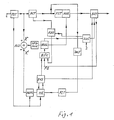
- Fig. 1 ein Blockschaltbild einer Codiereinrichtung, bei der Teilbildbereiche übertragen werden und
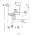
- Fig. 2 ein Blockschaltbild einer Codiereinrichtung, bei der Prädiktionsfehler übertragen werden.
- Fig. 1 is a block diagram of a coding device in which fields are transmitted and
- Fig. 2 is a block diagram of a coding device in which prediction errors are transmitted.
Beim Ausführungsbeispiel nach Fig. 1 wird eine PCM Bildsequenz, z.B. aus 2 Vollbildern, am Punkt 1 zugeführt. Diese Bildsequenz wird an einen Bildspeicher PST weitergeleitet. Die abgespeicherte Bildsequenz wird sowohl einem Bewegungsschätzer (motion estimator) ME als auch über einen Addierer ADD einer Einrichtung zum Ermitteln von Restfehlern DFD-SUM und einer wahrnehmungsadaptiven Transformationscodiereinrichtung DCT zugeleitet. Als Bewegungsschätzer kann eine bekannte Einrichtung verwendet werden. Besonders geeignet ist ein hierarchisch strukturierter Bewegungsschätzer gemäß EP 236 519 A1. Als Transformationscodiereinrichtung kann die aus Esprit'86, Seiten 217 bis 218, s.o., bekannte Einrichtung verwendet werden oder auch Einrichtungen gemäß EP 13 069 A1, GB 21 41 847 A oder Philips techn. Rev. 38, 1978/79, No. 4/5, Seiten 119 bis 130. Die der DCT-Transformation unterzogene Bildsequenz wird in einem Speicher FST abgespeichert sowie in der Einrichtung JDCT einer zur DCT-Transformation inversen Transformation unterzogen. Über einen weiteren Bildspeicher FIT wird die rücktransformierte Bildsequenz dem Bewegungsschätzer ME zur Verfügung gestellt. Der Bewegungsschätzer ME liefert über einen Interpolator MCFI (motion compensating frame interpolator) Bildpunkte X′ aus dem bewegungskompensierten Teilbildbereich des vorangegangenen Bildes. Für den Interpolator MCFI kann auf bekannte Realisierungen zurückgegriffen werden, beispielsweise auf den aus EP 236 519 A1 bekannten "Motion Compensating Interpolation Filter". Dieser berechnet jeden Bildpunkt als Funktion aus den Bewegungsvektoren, die der Bewegungsschätzer ME liefert, und der zeitlichen Position der Bildpunkte. Über einen Addierer ADD wird jeweils die Differenz zwischen aktuellen Bildpunkten X und Bildpunkten X′ gebildet. Mittels der Einrichtung DFD-SUM werden diese Differenzen nach folgender Beziehung:
DFD = SUM |x-x′|
▭ - Teilbildbereich/Block
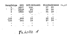
zu einem Restfehler aufsummiert, welcher ein Gütekriterium für die bewegungskompensierte Rekonstruktion bezüglich der Teilbildbereiche darstellt. Diese Restfehler DFD werden nun in absteigender Fehlergröße durch eine Einrichtung BSEL geordnet (Tabelle 1). Die Einrichtung BSEL steuert einen Multiplexer MUX derart, daß nur solche im Speicher FST abgelegten DCT transformierten Teilbildbereiche an einen Pufferspeicher BUF weitergeleitet werden, die die größten Restfehler aufweisen. Die Bewegungsvektoren, die mit dem Displacementschätzer ME ermittelt werden und in einem Vektorspeicher BVS abgelegt sind, werden z.B. VWL (variable word length) codiert und ebenfalls dem Pufferspeicher BUF zugeführt. Synchron- und Steuerinformation wird über den Punkt 2 einer Aufbereitungsstufe ZUS zugeführt. Zusammen mit der Information über die geordneten Restfehler - BSEL - wird diese Zusatzinformation aufbereitet und codiert und zum Pufferspeicher BUF geleitet. Sie enthält beispielsweise die Blockadresse (letzte 2 Spalten in Tabelle 1) und die DCT-Bitzahl, d.h. die für die DCT-Codierung eines Teilbildbereichs/Blockes erforderliche Anzahl der Bits. Letztere Information wird von einem DCT-Blockbitzahl-Speicher BBZ geliefert, der an die Transformationscodiereinrichtung angeschlossen ist. Bei einer 64 kbit/s-Übertragung stehen nach der Codierung von Synchron- und Steuerinformation sowie der Bewegungsvektoren für die Ubertragung von DCT-Blöcken für ein bestimmtes Bild (vgl. Tabelle 1) z.B. noch 4723 bit zur Verfügung. Die Bitsumme aller Blöcke bis zum Block 122 beträgt einschließlich der Blockadressierung 4709 bit. Es können daher die ersten 122 DCT-Blöcke mit den größten Restfehlern DFD übertragen werden.In the exemplary embodiment according to FIG. 1, a PCM image sequence, for example from 2 full images, is fed in at
DFD = SUM | xx ′ |
▭ - drawing area / block
summed up to a residual error, which represents a quality criterion for the motion-compensated reconstruction with respect to the partial image areas. These residual errors DFD are now sorted in descending error size by a device BSEL (Table 1). The device BSEL controls a multiplexer MUX in such a way that only those DCT-transformed partial image areas stored in the memory FST are forwarded to a buffer memory BUF which have the greatest remaining errors. The motion vectors, which are determined with the displacement estimator ME and are stored in a vector memory BVS, are coded, for example, VWL (variable word length) and also fed to the buffer memory BUF. Synchronous and control information is fed via
Zum Ansteuern der Einrichtung BSEL ist ein Bitzähler BITC vorgesehen, dem wiederum die Vektorbitzahl vom Vektorspeicher BVS, die DCT-Blockbitzahl und der Füllstand FS des Pufferspeichers BUF als Steuerkriterium zugeführt ist. Der Bitzähler BITC ermöglicht dadurch immer die maximal mögliche Ausnutzung des Übertragungskanals.To control the device BSEL, a bit counter BITC is provided, which in turn is supplied with the vector bit number from the vector memory BVS, the DCT block bit number and the fill level FS of the buffer memory BUF as a control criterion. The BITC bit counter always enables the maximum possible utilization of the transmission channel.
Anstelle der Übertragung der codierten Teilbildbereichs-/Blockinformation kann auch eine Übertragung der codierten Prädiktionsfehler vorgenommen werden. Eine Einrichtung hierzu zeigt Fig. 2, wobei die den in Fig. 1 entsprechenden Baugruppen mit gestrichenen Bezugszeichen dargestellt sind.Instead of the transmission of the coded field area / block information, a transmission of the coded prediction errors can also be carried out. A device for this is shown in FIG. 2, the subassemblies corresponding to those in FIG. 1 being shown with crossed reference numerals.
In Abweichung zu Fig. 1 ist ein Addierer ADD′ zwischen den entsprechenden eingangsseitigen Bildspeicher und die Transformationscodiereinrichtung DCT′ geschaltet. Dem Addierer ADD′ ist am Minuendeneingang das Ausgangssignal des der Fig. 1 entsprechenden Interpolators MCFI′ zugeführt. Die entsprechende Einrichtung DFD-SUM′ wertet das Ausgangssignal dieses Addierers ADD′ aus. Ein weiterer Addierer ADDW ist zwischen die entsprechende Einrichtung zur inversen DCT-Transformation JDCT′ und Speicher FIT′ geschaltet. An seinem Minuendeneingang wird diesem weiteren Addierer ADDW das Ausgangssignal des entsprechenden Interpolators MCFI′ zugeführt. Durch diese Modifikation bezüglich der Realisierung nach Fig. 1 wird dem Bewegungsschätzer ME′ nicht das rücktransformierte Bild zugeführt, sondern das rekonstruierte Bild, wobei zur Rekonstruktion das bewegungskompensierte Prädiktionsbild (Ausgangssignal des Interpolators MCFI′) und das nichttransformierte Fehlerbild herangezogen wird. Dadurch wird nicht das PCM-Bild DCT-codiert, sondern der bewegungskompensierte Prädiktionsfehler. Dieser bewegungskompensierte Prädiktionsfehler wird auch als Eingangssignal der Einrichtung DFD-SUM′ verwendet.In deviation from Fig. 1, an adder ADD 'is connected between the corresponding input image memory and the transform coding device DCT'. The adder ADD 'is the output signal of the corresponding interpolator MCFI' supplied at the end of the minute. The corresponding device DFD-SUM 'evaluates the output signal of this adder ADD'. Another adder ADDW is connected between the corresponding device for inverse DCT transformation JDCT 'and memory FIT'. The output signal of the corresponding interpolator MCFI 'is fed to this additional adder ADDW at its minute end input. 1, the motion estimator ME 'is not fed the back-transformed image, but the reconstructed image, the motion-compensated prediction image (output signal of the interpolator MCFI') and the non-transformed error image being used for the reconstruction. This will not the PCM picture is DCT-coded, but the motion-compensated prediction error. This motion-compensated prediction error is also used as the input signal of the device DFD-SUM '.
Als Gütekriterium kann anstelle des Restfehlers (Bildverschiebungsdifferenz) DFD = SUM | x-x′ |
auch der Ausdruck
DFD′ = SUM (x-x′)²
verwendet werden oder ähnliche Beziehungen. Das Gütekriterium kann nicht nur zur Auswahl der zu übertragenden Blöcke herangezogen werden, sondern auch zur Steuerung der Codierdatenrate, z.B. durch eine Veränderung der Quantisierung.Instead of the residual error (image shift difference), DFD = SUM | xx ′ |
also the expression
DFD ′ = SUM (xx ′) ²
used or similar relationships. The quality criterion can be used not only to select the blocks to be transmitted, but also to control the coding data rate, for example by changing the quantization.
Unter dem bisher verwendeten Begriff "Teilbildbereich" wurde ein matrixförmiger Bereich - Block - verstanden. Anstelle von solchen matrixförmigen Bereichen kann auch eine andere Struktur, z.B. in Form von Elementen eines Musters gelegt werden.The previously used term "partial image area" was understood to mean a matrix-shaped area - block. Instead of such matrix areas, another structure, e.g. in the form of elements of a pattern.
Claims (8)
a) Ermitteln von Bewegungsvektoren für Teilbildbereiche und Codieren derselben,
b) Codieren der Teilbildbereiche im Sinne einer Redundanz- und Irrelevanzverminderung,
c) Aufbereiten eines Übertragungssignals, gebildet aus den codierten Bewegungsvektoren, gegebenenfalls Steuer- und/oder Synchroninformation, und nur solcher codierter Teilbildbereiche, bei denen in Abhängigkeit eines Gütekriteriums für die bewegungskompensierte Rekonstruktion die größten Abweichungen auftreten, unabhängig von ihrer zeitlichen Reihenfolge, wobei die Schritte a) und b) den Oberbegriff und der Schritt c) das Kennzeichen bilden.1. Image coding method for the transmission of image information over a channel with limited data capacity with the following steps:
a) determining motion vectors for partial image areas and coding them,
b) coding of the partial image areas in the sense of a reduction in redundancy and irrelevance,
c) Processing a transmission signal, formed from the coded motion vectors, possibly control and / or synchronous information, and only those coded partial image areas in which the greatest deviations occur depending on a quality criterion for the motion-compensated reconstruction, regardless of their chronological order, the steps a) and b) the generic term and step c) form the mark.
a) Ermitteln von Bewegungsvektoren für Teilbildbereiche und Codieren derselben,
b) Codieren der bewegungskompensierten Prädiktionsfehler im Sinne einer Redundanz- und Irrelevanzverminderung,
c) Aufbereiten eines Übertragungssignals, gebildet aus den codierten Bewegungsvektoren, gegebenenfalls Steuer- und/oder Synchroninformation, und nur solcher codierter Prädiktionsfehler, bei denen in Abhängigkeit eines Gütekriteriums für die bewegungskompensierte Rekonstruktion die größten Abweichungen auftreten, unabhängig von ihrer zeitlichen Reihenfolge, wobei die Schritte a) und b) den Oberbegriff und der Schritt c) das Kennzeichen bilden.2. Image coding method for the transmission of image information via a channel with limited data capacity with the following steps:
a) determining motion vectors for partial image areas and coding them,
b) coding of the motion-compensated prediction errors in the sense of a reduction in redundancy and irrelevance,
c) preparation of a transmission signal, formed from the coded motion vectors, possibly control and / or synchronous information, and only those coded prediction errors in which the greatest deviations occur depending on a quality criterion for the motion-compensated reconstruction, regardless of their chronological order, with steps a) and b) forming the generic term and step c) the characteristic.
DFD = SUM |x - x′|
als Gütekriterium, wobei mit SUM die Summe über alle Teilbildbereichs-/Blockelemente,
x der Bildpunkt aus einem PCM-Block des aktuellen Bildes,
x′ der entsprechende Bildpunkt aus dem bewegungskompensierten Teilbildbereich / Block des letzten Bildes bezeichnet ist.3. The method according to claim 1 or 2, characterized by the image sequence shift difference (displaced frame difference - DFD)
DFD = SUM | x - x ′ |
as a quality criterion, whereby with SUM the sum over all field area / block elements,
x the pixel from a PCM block of the current image,
x 'the corresponding pixel from the motion-compensated partial image area / block of the last image is designated.
DFD′ = SUM (x - x′)²
als Gütekriterium, wobei mit SUM die Summe über alle Teilbildbereichs-/Blockelemente,
x der Bildpunkt aus einem PCM-Block des aktuellen Bildes,
x′ der entsprechende Bildpunkt aus dem bewegungskompensierten Teilbildbereich/Block des letzten Bildes bezeichnet ist.4. The method according to claim 1 or 2, characterized by the expression
DFD ′ = SUM (x - x ′) ²
as a quality criterion, whereby with SUM the sum over all field area / block elements,
x the pixel from a PCM block of the current image,
x 'the corresponding pixel from the motion-compensated partial image area / block of the last image is designated.
- Ermitteln der Restfehler der mit den Bewegungsvektoren bewegungskompensierten Teilbildbereiche/Blöcke,
- Ordnen der Restfehler nach absteigender Fehlergröße,
- Auswählen der zu übertragenden Teilbildbereiche/Blöcke in Abhängigkeit der größten Restfehler.6. Image coding method according to one of claims 1, 3, 4 or 5, characterized by
Determining the residual errors of the partial image areas / blocks motion-compensated with the motion vectors,
- order the remaining errors according to the decreasing error size,
- Selection of the partial image areas / blocks to be transferred depending on the largest remaining errors.
- eine bewegungsadaptive Transformationscodiereinrichtung (DCT) für Teilbildbereiche,
- eine Einrichtung (ME, BSV) zum Ermitteln von Bewegungsvektoren für Teilbildbereiche,
- eine Einrichtung zum Ermitteln der Restfehler (ADD, DFD-SUM) der mit den Bewegungsvektoren bewegungskompensierten Teilbildbereiche/Blöcke,
- eine Einrichtung zum Auswählen der codierten zu übertragenden Teilbildbereiche/Blöcke in Abhängigkeit der größten Restfehler (BSEL, MUX),
- eine Einrichtung (BUF) zum Zusammenfügen der codierten Bewegungsvektoren, der ausgewählten codierten Teilbildbereiche/Blöcke und gegebenenfalls Steuer- und/oder Synchroninformation zu einem Übertragungssignal.7. Image coding device, in particular for performing the method according to one of claims 1, 3, 4, 5 or 6, characterized by
a motion-adaptive transformation coding device (DCT) for partial image areas,
a device (ME, BSV) for determining motion vectors for partial image areas,
a device for determining the residual errors (ADD, DFD-SUM) of the partial image areas / blocks that are motion-compensated with the motion vectors,
a device for selecting the coded sub-picture areas / blocks to be transmitted depending on the largest residual errors (BSEL, MUX),
- A device (BUF) for assembling the coded motion vectors, the selected coded field areas / blocks and possibly control and / or synchronous information into a transmission signal.
- eine Transformationscodiereinrichtung (DCT′) für bewegungskompensierte Prädiktionsfehler,
- eine Einrichtung (ME′, BSV′) zum Ermitteln von Bewegungsvektoren für Teilbildbereiche,
- eine Einrichtung zum Ermitteln der Restfehler (ADD′, DFD-SUM′) für bewegungskompensierte Prädiktionsfehler,
- eine Einrichtung zum Auswählen der codierten zu übertragenden bewegungskompensierten Prädiktionsfehler in Abhängigkeit der größten Restfehler (BSEL′, MUX′),
- eine Einrichtung (BUF′) zum Zusammenfügen der codierten Bewegungsvektoren, der ausgewählten codierten bewegungskompensierten Prädiktionsfehler und gegebenenfalls Steuer- und/oder Synchroninformation zu einem Ubertragungssignal.8. Image coding device, in particular for performing the method according to one of claims 2, 3, 4, 5 or 6, characterized by
- a transformation coding device (DCT ′) for motion-compensated prediction errors,
a device (ME ′, BSV ′) for determining motion vectors for partial image areas,
- a device for determining the residual errors (ADD ′, DFD-SUM ′) for motion-compensated prediction errors,
a device for selecting the coded motion-compensated prediction errors to be transmitted as a function of the largest residual errors (BSEL ′, MUX ′),
- A device (BUF ') for assembling the coded motion vectors, the selected coded motion-compensated prediction errors and possibly control and / or synchronous information into a transmission signal.
Applications Claiming Priority (2)
| Application Number | Priority Date | Filing Date | Title |
|---|---|---|---|
| DE3820037 | 1988-06-13 | ||
| DE3820037A DE3820037A1 (en) | 1988-06-13 | 1988-06-13 | IMAGE CODING METHOD AND DEVICE |
Publications (3)
| Publication Number | Publication Date |
|---|---|
| EP0346635A2 true EP0346635A2 (en) | 1989-12-20 |
| EP0346635A3 EP0346635A3 (en) | 1991-03-27 |
| EP0346635B1 EP0346635B1 (en) | 1994-09-07 |
Family
ID=6356418
Family Applications (1)
| Application Number | Title | Priority Date | Filing Date |
|---|---|---|---|
| EP89108913A Expired - Lifetime EP0346635B1 (en) | 1988-06-13 | 1989-05-18 | Method and device for coding pictures |
Country Status (2)
| Country | Link |
|---|---|
| EP (1) | EP0346635B1 (en) |
| DE (2) | DE3820037A1 (en) |
Cited By (9)
| Publication number | Priority date | Publication date | Assignee | Title |
|---|---|---|---|---|
| EP0439675A3 (en) * | 1990-02-01 | 1992-08-12 | Ant Nachrichtentechnik Gmbh | Method for the processing of picture data, especially for still picture transmission |
| FR2716556A1 (en) * | 1994-02-23 | 1995-08-25 | Bosch Gmbh Robert | A source encoding method for subdividing an image into image ranges of fixed size. |
| WO1997016026A1 (en) * | 1995-10-27 | 1997-05-01 | University Of Strathclyde | Data compression |
| WO1997047138A1 (en) * | 1996-06-06 | 1997-12-11 | Berners Lee C P | Apparatus and method for encoding data |
| EP0734179A3 (en) * | 1995-03-20 | 1998-03-04 | Daewoo Electronics Co., Ltd | Method and apparatus for selectively encoding/decoding a video signal |
| US6061401A (en) * | 1995-03-20 | 2000-05-09 | Daewoo Electronics Co., Ltd. | Method and apparatus for selectively encoding/decoding a video signal |
| US7039108B2 (en) | 2000-09-29 | 2006-05-02 | Robert Bosch Gmbh | Method and device for coding and decoding image sequences |
| US7464027B2 (en) | 2004-02-13 | 2008-12-09 | Fraunhofer-Gesellschaft Zur Foerderung Der Angewandten Forschung E.V. | Method and device for quantizing an information signal |
| US7716042B2 (en) | 2004-02-13 | 2010-05-11 | Gerald Schuller | Audio coding |
Families Citing this family (1)
| Publication number | Priority date | Publication date | Assignee | Title |
|---|---|---|---|---|
| DE102004007200B3 (en) | 2004-02-13 | 2005-08-11 | Fraunhofer-Gesellschaft zur Förderung der angewandten Forschung e.V. | Device for audio encoding has device for using filter to obtain scaled, filtered audio value, device for quantizing it to obtain block of quantized, scaled, filtered audio values and device for including information in coded signal |
Family Cites Families (2)
| Publication number | Priority date | Publication date | Assignee | Title |
|---|---|---|---|---|
| US4670851A (en) * | 1984-01-09 | 1987-06-02 | Mitsubishi Denki Kabushiki Kaisha | Vector quantizer |
| US4727422A (en) * | 1985-06-03 | 1988-02-23 | Picturetel Corporation | Method and apparatus for efficiently communicating image sequence having improved motion compensation |
-
1988
- 1988-06-13 DE DE3820037A patent/DE3820037A1/en not_active Withdrawn
-
1989
- 1989-05-18 DE DE58908301T patent/DE58908301D1/en not_active Expired - Lifetime
- 1989-05-18 EP EP89108913A patent/EP0346635B1/en not_active Expired - Lifetime
Cited By (13)
| Publication number | Priority date | Publication date | Assignee | Title |
|---|---|---|---|---|
| EP0439675A3 (en) * | 1990-02-01 | 1992-08-12 | Ant Nachrichtentechnik Gmbh | Method for the processing of picture data, especially for still picture transmission |
| FR2716556A1 (en) * | 1994-02-23 | 1995-08-25 | Bosch Gmbh Robert | A source encoding method for subdividing an image into image ranges of fixed size. |
| EP0734179A3 (en) * | 1995-03-20 | 1998-03-04 | Daewoo Electronics Co., Ltd | Method and apparatus for selectively encoding/decoding a video signal |
| US6061401A (en) * | 1995-03-20 | 2000-05-09 | Daewoo Electronics Co., Ltd. | Method and apparatus for selectively encoding/decoding a video signal |
| GB2306840B (en) * | 1995-10-27 | 1999-12-01 | Univ Strathclyde | Data compression |
| US6049632A (en) * | 1995-10-27 | 2000-04-11 | University Of Strathclyde | Data compression |
| WO1997016026A1 (en) * | 1995-10-27 | 1997-05-01 | University Of Strathclyde | Data compression |
| FR2749688A1 (en) * | 1996-06-06 | 1997-12-12 | Berners Lee C P | APPARATUS AND METHOD FOR ENCODING DATA |
| WO1997047138A1 (en) * | 1996-06-06 | 1997-12-11 | Berners Lee C P | Apparatus and method for encoding data |
| US5999217A (en) * | 1996-06-06 | 1999-12-07 | Berners-Lee; Charles Peter | Apparatus and method for encoding data |
| US7039108B2 (en) | 2000-09-29 | 2006-05-02 | Robert Bosch Gmbh | Method and device for coding and decoding image sequences |
| US7464027B2 (en) | 2004-02-13 | 2008-12-09 | Fraunhofer-Gesellschaft Zur Foerderung Der Angewandten Forschung E.V. | Method and device for quantizing an information signal |
| US7716042B2 (en) | 2004-02-13 | 2010-05-11 | Gerald Schuller | Audio coding |
Also Published As
| Publication number | Publication date |
|---|---|
| DE58908301D1 (en) | 1994-10-13 |
| DE3820037A1 (en) | 1989-12-14 |
| EP0346635B1 (en) | 1994-09-07 |
| EP0346635A3 (en) | 1991-03-27 |
Similar Documents
| Publication | Publication Date | Title |
|---|---|---|
| DE69522861T2 (en) | Method and device for code conversion of coded data stream | |
| DE69323523T2 (en) | Device for coding digital image-representing signals and corresponding decoding device | |
| DE69323156T2 (en) | Image data compression / decompression system | |
| DE10190285B4 (en) | Method and system for processing compressed video signals | |
| DE69033508T2 (en) | Method for decoding a video signal | |
| DE69021500T2 (en) | Conditional motion-compensated interpolation of digital moving picture signals. | |
| DE69414931T2 (en) | Transcoder | |
| DE69225556T2 (en) | Picture-to-picture prediction method and picture signal coding / decoding device | |
| DE69521238T2 (en) | Image data quantization in image compression | |
| DE69530336T2 (en) | Motion compensation for interlaced digital video signals | |
| DE69027710T2 (en) | Moving image signal encoding and decoding device | |
| DE69512548T2 (en) | Method and device for avoiding repetitive random errors in transformation coefficients of moving image signals | |
| DE3814627C2 (en) | ||
| DE69430877T2 (en) | Image encoding method and device | |
| DE69031045T2 (en) | Device for adaptive interframe prediction decoding of a video signal | |
| DE69224250T2 (en) | Derivation and use of motion vectors in a differential pulse code modulation system | |
| EP0276753B1 (en) | Method and apparatus for transmitting digital information and/or for recording and reproducing | |
| DE69106415T2 (en) | Device for coding / decoding image signals. | |
| DE3874703T2 (en) | CODING AND DECODING METHOD AND DEVICE FOR IMAGE TRANSFER OVER A NETWORK WITH A VARIABLE DATA FLOW. | |
| DE69736852T2 (en) | Coding and decoding system for moving pictures with arbitrarily shaped objects | |
| DE69428034T2 (en) | Image signal encoding and decoding | |
| DE69232215T2 (en) | Device for image coding | |
| DE69331174T2 (en) | Image processing device | |
| EP0346635B1 (en) | Method and device for coding pictures | |
| DE4408522C2 (en) | Device for processing image data and method for processing image data |
Legal Events
| Date | Code | Title | Description |
|---|---|---|---|
| PUAI | Public reference made under article 153(3) epc to a published international application that has entered the european phase |
Free format text: ORIGINAL CODE: 0009012 |
|
| AK | Designated contracting states |
Kind code of ref document: A2 Designated state(s): DE FR GB IT NL |
|
| PUAL | Search report despatched |
Free format text: ORIGINAL CODE: 0009013 |
|
| 17P | Request for examination filed |
Effective date: 19901228 |
|
| AK | Designated contracting states |
Kind code of ref document: A3 Designated state(s): DE FR GB IT NL |
|
| 17Q | First examination report despatched |
Effective date: 19930225 |
|
| GRAA | (expected) grant |
Free format text: ORIGINAL CODE: 0009210 |
|
| ITF | It: translation for a ep patent filed | ||
| AK | Designated contracting states |
Kind code of ref document: B1 Designated state(s): DE FR GB IT NL |
|
| REF | Corresponds to: |
Ref document number: 58908301 Country of ref document: DE Date of ref document: 19941013 |
|
| ET | Fr: translation filed | ||
| GBT | Gb: translation of ep patent filed (gb section 77(6)(a)/1977) |
Effective date: 19941125 |
|
| PLBE | No opposition filed within time limit |
Free format text: ORIGINAL CODE: 0009261 |
|
| STAA | Information on the status of an ep patent application or granted ep patent |
Free format text: STATUS: NO OPPOSITION FILED WITHIN TIME LIMIT |
|
| 26N | No opposition filed | ||
| REG | Reference to a national code |
Ref country code: FR Ref legal event code: D9 Free format text: CORRECTION |
|
| REG | Reference to a national code |
Ref country code: GB Ref legal event code: IF02 |
|
| PGFP | Annual fee paid to national office [announced via postgrant information from national office to epo] |
Ref country code: IT Payment date: 20080526 Year of fee payment: 20 |
|
| PGFP | Annual fee paid to national office [announced via postgrant information from national office to epo] |
Ref country code: NL Payment date: 20080523 Year of fee payment: 20 Ref country code: DE Payment date: 20080728 Year of fee payment: 20 |
|
| PGFP | Annual fee paid to national office [announced via postgrant information from national office to epo] |
Ref country code: GB Payment date: 20080522 Year of fee payment: 20 |
|
| REG | Reference to a national code |
Ref country code: GB Ref legal event code: PE20 Expiry date: 20090517 |
|
| NLV7 | Nl: ceased due to reaching the maximum lifetime of a patent |
Effective date: 20090518 |
|
| PG25 | Lapsed in a contracting state [announced via postgrant information from national office to epo] |
Ref country code: NL Free format text: LAPSE BECAUSE OF EXPIRATION OF PROTECTION Effective date: 20090518 |
|
| PG25 | Lapsed in a contracting state [announced via postgrant information from national office to epo] |
Ref country code: GB Free format text: LAPSE BECAUSE OF EXPIRATION OF PROTECTION Effective date: 20090517 |
|
| PGFP | Annual fee paid to national office [announced via postgrant information from national office to epo] |
Ref country code: FR Payment date: 20080519 Year of fee payment: 20 |