EP0346502A1 - Verfahren und Vorrichtung zur Elektrodesionisation - Google Patents
Verfahren und Vorrichtung zur Elektrodesionisation Download PDFInfo
- Publication number
- EP0346502A1 EP0346502A1 EP88108702A EP88108702A EP0346502A1 EP 0346502 A1 EP0346502 A1 EP 0346502A1 EP 88108702 A EP88108702 A EP 88108702A EP 88108702 A EP88108702 A EP 88108702A EP 0346502 A1 EP0346502 A1 EP 0346502A1
- Authority
- EP
- European Patent Office
- Prior art keywords
- liquid
- compartments
- ion
- exchange resin
- stage
- Prior art date
- Legal status (The legal status is an assumption and is not a legal conclusion. Google has not performed a legal analysis and makes no representation as to the accuracy of the status listed.)
- Granted
Links
- 238000009296 electrodeionization Methods 0.000 title claims abstract description 37
- 238000000034 method Methods 0.000 title description 20
- 239000007788 liquid Substances 0.000 claims abstract description 63
- 150000002500 ions Chemical class 0.000 claims abstract description 48
- 239000012528 membrane Substances 0.000 claims abstract description 36
- 239000011324 bead Substances 0.000 claims abstract description 25
- NWUYHJFMYQTDRP-UHFFFAOYSA-N 1,2-bis(ethenyl)benzene;1-ethenyl-2-ethylbenzene;styrene Chemical compound C=CC1=CC=CC=C1.CCC1=CC=CC=C1C=C.C=CC1=CC=CC=C1C=C NWUYHJFMYQTDRP-UHFFFAOYSA-N 0.000 claims abstract description 15
- 150000001450 anions Chemical class 0.000 claims abstract description 12
- 239000003957 anion exchange resin Substances 0.000 claims abstract description 9
- 238000000926 separation method Methods 0.000 claims abstract description 9
- 239000003729 cation exchange resin Substances 0.000 claims abstract description 8
- 125000006850 spacer group Chemical group 0.000 claims description 35
- 238000005342 ion exchange Methods 0.000 claims description 15
- 239000000203 mixture Substances 0.000 claims description 11
- 150000001768 cations Chemical class 0.000 claims description 9
- 239000008247 solid mixture Substances 0.000 claims 2
- 239000003456 ion exchange resin Substances 0.000 abstract description 11
- 229920003303 ion-exchange polymer Polymers 0.000 abstract description 11
- 230000000717 retained effect Effects 0.000 abstract description 3
- 210000004379 membrane Anatomy 0.000 description 32
- 238000012360 testing method Methods 0.000 description 30
- XLYOFNOQVPJJNP-UHFFFAOYSA-N water Substances O XLYOFNOQVPJJNP-UHFFFAOYSA-N 0.000 description 27
- 230000000779 depleting effect Effects 0.000 description 25
- 239000000463 material Substances 0.000 description 16
- FAPWRFPIFSIZLT-UHFFFAOYSA-M Sodium chloride Chemical compound [Na+].[Cl-] FAPWRFPIFSIZLT-UHFFFAOYSA-M 0.000 description 8
- 239000012141 concentrate Substances 0.000 description 8
- 238000013461 design Methods 0.000 description 7
- 239000003792 electrolyte Substances 0.000 description 6
- 125000000129 anionic group Chemical class 0.000 description 5
- 125000002091 cationic group Chemical class 0.000 description 5
- 230000000694 effects Effects 0.000 description 5
- 238000000909 electrodialysis Methods 0.000 description 5
- 239000011347 resin Substances 0.000 description 5
- 229920005989 resin Polymers 0.000 description 5
- 239000011780 sodium chloride Substances 0.000 description 5
- CHRJZRDFSQHIFI-UHFFFAOYSA-N 1,2-bis(ethenyl)benzene;styrene Chemical compound C=CC1=CC=CC=C1.C=CC1=CC=CC=C1C=C CHRJZRDFSQHIFI-UHFFFAOYSA-N 0.000 description 4
- 210000000188 diaphragm Anatomy 0.000 description 4
- 239000000047 product Substances 0.000 description 4
- 150000003839 salts Chemical class 0.000 description 4
- 239000003643 water by type Substances 0.000 description 4
- LSNNMFCWUKXFEE-UHFFFAOYSA-M Bisulfite Chemical compound OS([O-])=O LSNNMFCWUKXFEE-UHFFFAOYSA-M 0.000 description 3
- 238000010276 construction Methods 0.000 description 3
- 239000012530 fluid Substances 0.000 description 3
- 241001466538 Gymnogyps Species 0.000 description 2
- VYPSYNLAJGMNEJ-UHFFFAOYSA-N Silicium dioxide Chemical compound O=[Si]=O VYPSYNLAJGMNEJ-UHFFFAOYSA-N 0.000 description 2
- UIIMBOGNXHQVGW-UHFFFAOYSA-M Sodium bicarbonate Chemical compound [Na+].OC([O-])=O UIIMBOGNXHQVGW-UHFFFAOYSA-M 0.000 description 2
- QGZKDVFQNNGYKY-UHFFFAOYSA-O ammonium group Chemical group [NH4+] QGZKDVFQNNGYKY-UHFFFAOYSA-O 0.000 description 2
- 230000005465 channeling Effects 0.000 description 2
- 230000000052 comparative effect Effects 0.000 description 2
- 238000010586 diagram Methods 0.000 description 2
- 239000000835 fiber Substances 0.000 description 2
- 230000001939 inductive effect Effects 0.000 description 2
- 238000004519 manufacturing process Methods 0.000 description 2
- 230000010287 polarization Effects 0.000 description 2
- 239000002516 radical scavenger Substances 0.000 description 2
- 238000011084 recovery Methods 0.000 description 2
- 230000000452 restraining effect Effects 0.000 description 2
- 239000007787 solid Substances 0.000 description 2
- 238000012546 transfer Methods 0.000 description 2
- 239000012498 ultrapure water Substances 0.000 description 2
- 229920003934 Aciplex® Polymers 0.000 description 1
- OYPRJOBELJOOCE-UHFFFAOYSA-N Calcium Chemical compound [Ca] OYPRJOBELJOOCE-UHFFFAOYSA-N 0.000 description 1
- JLVVSXFLKOJNIY-UHFFFAOYSA-N Magnesium ion Chemical compound [Mg+2] JLVVSXFLKOJNIY-UHFFFAOYSA-N 0.000 description 1
- 239000002033 PVDF binder Substances 0.000 description 1
- 239000004698 Polyethylene Substances 0.000 description 1
- 238000005349 anion exchange Methods 0.000 description 1
- 230000000712 assembly Effects 0.000 description 1
- 238000000429 assembly Methods 0.000 description 1
- 230000015572 biosynthetic process Effects 0.000 description 1
- 239000012267 brine Substances 0.000 description 1
- 239000011575 calcium Substances 0.000 description 1
- 229910001424 calcium ion Inorganic materials 0.000 description 1
- 238000005341 cation exchange Methods 0.000 description 1
- 238000004140 cleaning Methods 0.000 description 1
- 238000004891 communication Methods 0.000 description 1
- 238000005056 compaction Methods 0.000 description 1
- 230000002860 competitive effect Effects 0.000 description 1
- 239000000356 contaminant Substances 0.000 description 1
- 238000010612 desalination reaction Methods 0.000 description 1
- 238000009792 diffusion process Methods 0.000 description 1
- 238000007865 diluting Methods 0.000 description 1
- 238000005516 engineering process Methods 0.000 description 1
- 239000000945 filler Substances 0.000 description 1
- 239000002509 fulvic acid Substances 0.000 description 1
- 239000004021 humic acid Substances 0.000 description 1
- 239000003014 ion exchange membrane Substances 0.000 description 1
- 229920005610 lignin Polymers 0.000 description 1
- 238000004811 liquid chromatography Methods 0.000 description 1
- 239000011244 liquid electrolyte Substances 0.000 description 1
- 239000012263 liquid product Substances 0.000 description 1
- 229910001425 magnesium ion Inorganic materials 0.000 description 1
- 238000012423 maintenance Methods 0.000 description 1
- 238000005374 membrane filtration Methods 0.000 description 1
- 238000002156 mixing Methods 0.000 description 1
- BVWUEIUNONATML-UHFFFAOYSA-N n-benzylethenamine Chemical compound C=CNCC1=CC=CC=C1 BVWUEIUNONATML-UHFFFAOYSA-N 0.000 description 1
- 239000002245 particle Substances 0.000 description 1
- -1 polyethylene Polymers 0.000 description 1
- 229920000573 polyethylene Polymers 0.000 description 1
- 238000000746 purification Methods 0.000 description 1
- 239000008213 purified water Substances 0.000 description 1
- 238000011160 research Methods 0.000 description 1
- 238000007789 sealing Methods 0.000 description 1
- 239000000377 silicon dioxide Substances 0.000 description 1
- 235000017557 sodium bicarbonate Nutrition 0.000 description 1
- 229910000030 sodium bicarbonate Inorganic materials 0.000 description 1
- MKWYFZFMAMBPQK-UHFFFAOYSA-J sodium feredetate Chemical compound [Na+].[Fe+3].[O-]C(=O)CN(CC([O-])=O)CCN(CC([O-])=O)CC([O-])=O MKWYFZFMAMBPQK-UHFFFAOYSA-J 0.000 description 1
- HPALAKNZSZLMCH-UHFFFAOYSA-M sodium;chloride;hydrate Chemical compound O.[Na+].[Cl-] HPALAKNZSZLMCH-UHFFFAOYSA-M 0.000 description 1
- 150000003440 styrenes Chemical class 0.000 description 1
- 239000000126 substance Substances 0.000 description 1
- 229920001864 tannin Polymers 0.000 description 1
- 239000001648 tannin Substances 0.000 description 1
- 235000018553 tannin Nutrition 0.000 description 1
- 238000011144 upstream manufacturing Methods 0.000 description 1
- 239000002699 waste material Substances 0.000 description 1
Images


Classifications
-
- B—PERFORMING OPERATIONS; TRANSPORTING
- B01—PHYSICAL OR CHEMICAL PROCESSES OR APPARATUS IN GENERAL
- B01D—SEPARATION
- B01D61/00—Processes of separation using semi-permeable membranes, e.g. dialysis, osmosis or ultrafiltration; Apparatus, accessories or auxiliary operations specially adapted therefor
- B01D61/42—Electrodialysis; Electro-osmosis ; Electro-ultrafiltration; Membrane capacitive deionization
- B01D61/44—Ion-selective electrodialysis
- B01D61/46—Apparatus therefor
- B01D61/48—Apparatus therefor having one or more compartments filled with ion-exchange material, e.g. electrodeionisation
-
- B—PERFORMING OPERATIONS; TRANSPORTING
- B01—PHYSICAL OR CHEMICAL PROCESSES OR APPARATUS IN GENERAL
- B01J—CHEMICAL OR PHYSICAL PROCESSES, e.g. CATALYSIS OR COLLOID CHEMISTRY; THEIR RELEVANT APPARATUS
- B01J47/00—Ion-exchange processes in general; Apparatus therefor
- B01J47/02—Column or bed processes
- B01J47/06—Column or bed processes during which the ion-exchange material is subjected to a physical treatment, e.g. heat, electric current, irradiation or vibration
- B01J47/08—Column or bed processes during which the ion-exchange material is subjected to a physical treatment, e.g. heat, electric current, irradiation or vibration subjected to a direct electric current
-
- C—CHEMISTRY; METALLURGY
- C02—TREATMENT OF WATER, WASTE WATER, SEWAGE, OR SLUDGE
- C02F—TREATMENT OF WATER, WASTE WATER, SEWAGE, OR SLUDGE
- C02F1/00—Treatment of water, waste water, or sewage
- C02F1/46—Treatment of water, waste water, or sewage by electrochemical methods
- C02F1/469—Treatment of water, waste water, or sewage by electrochemical methods by electrochemical separation, e.g. by electro-osmosis, electrodialysis, electrophoresis
- C02F1/4693—Treatment of water, waste water, or sewage by electrochemical methods by electrochemical separation, e.g. by electro-osmosis, electrodialysis, electrophoresis electrodialysis
- C02F1/4695—Treatment of water, waste water, or sewage by electrochemical methods by electrochemical separation, e.g. by electro-osmosis, electrodialysis, electrophoresis electrodialysis electrodeionisation
Definitions
- This invention relates to a novel electrodeionization apparatus and method adapted to transfer ions in a liquid under the influence of a polar field. More specifically, this invention relates to an electrodeionization apparatus and method adapted to purify aqueous liquids to effect the production of high purity water.
- the first apparatus and method for treating liquids by electrodeionization was described by Kollsman in U.S. Patent Nos. 2,689,826 and 2,815,320.
- the first of these patents describes an apparatus and process for the removal of ions within a liquid mixture in a depleting chamber through a series of anionic and cationic diaphragms into a second volume of liquid in a concentration chamber under the influence of an electrical potential which causes the preselected ions to travel in a predetermined direction.
- the volume of the liquid being treated is depleted of ions while the volume of the second liquid becomes enriched with the transferred ions and carries them in concentrated form.
- the second of these patents describes the use of macroporous beads formed of ion exchange resins as a filler material positioned between the anionic or cationic diaphragms.
- This ion exchange resin acts as a path for ion transfer and also serves as an increased conductivity bridge between the membranes for the movement of ions.
- These patents represent the primary structural framework and theory of electrodeionization as a technique.
- electrodeionization refers to the process wherein an ion exchange material is positioned between the anionic and cationic diaphragms.
- electrodialysis relates to such a process which does not utilize ion exchange resins between the anionic and cationic diaphragms.
- U.S. Patent No. 4,632,745 discloses an electrodeionization apparatus including depletion compartments divided into subcompartments having a width between 0.3 and 4 inches and a thickness between 0.05 and 0.25 inch. It was found that when utilizing this apparatus, efficient ion removal from the depletion compartment is attained while requiring only low energy and while avoiding channeling.
- the electrodeionization apparatus of U.S. Patent No. 4,632,745 can employ one or more, e.g. two hydraulic stages with two separate independent electrical stages.
- an hydraulic stage comprises a given number, e.g. 30, of cell pairs in which a volume of water flows through.
- a cell pair comprises a cation and anion membrane which are bonded to a dilute spacer containing ion exchange resin as well as a concentrate spacer.
- An electrical stage comprises one anode and one cathode electrode which enclose the hydraulic stage.
- a one-stage stack design is employed for low salinity feed water, whereas a two-stage stack design can be employed for high salinity water.
- the purpose of a two-stage design is to obtain the maximum salt removal in the first stage without inducing polarization which is an inefficiency resulting in stream pH shifts.
- the upward pH shift of the concentrate stream will result in scaling if calcium or magnesium ions are present in the feed water to the stack.
- Maximum salt removal in the first stage without inducing polarization is about 80 percent.
- the product water from the first stage is fed into the second stage where the remaining salt (about 20%) is removed to obtain meg-ohm product quality.
- the water being deionized is passed between each cell pair only once without changing flow direction. the overall design guards against scaling in the first stage while optimizing the overall salt removal, membrane utilization and energy requirement.
- electrodialysis cannot product meg-ohm quality water because it is inefficient in the low salinity range and requires more membrane area and energy. It would be desirable to provide an electrodeionization apparatus and method which provides improved ion removal efficiency as compared to presently available apparatus.
- the present invention provides an electrodeionization method and apparatus for producing purified water of up to 10 meg-ohm centimeter quality or higher over long time periods while avoiding serious reduction of ion exchange resin performance and avoiding the formation of particulates and scale within the electrodeionization apparatus.
- the electrodeionization apparatus includes a plurality of electrodeionization compartments whose thickness, width and configuration are controlled and which contain ion exchange materials such as beads, fibers or the like.
- the electrodeionization ion depleting compartments wherein liquid is depleted of ions are formed from a spacer having a hollow central portion divided by ribs or the like to define subcompartments.
- the ion exchange resin beads within the subcompartments are retained in the subcompartments by bonding or physically restraining a cationic permeable membrane to one surface of the depleting compartments and to the ribs and bonding or physically restraining an anionic permeable membrane to the opposing surface of the depleting compartment to the ribs, thereby to define the subcompartments.
- the concentration compartments into which ions migrate from the depleting compartments are free of ion exchange beads.
- the electrodeionization apparatus can comprise a single stage or a plurality of stages in series wherein the process voltage can be controlled independently in each stage, if desired.
- the ion depleting compartments and the concentration compartments in each stage are positioned between an anode and a cathode.
- Each stage contains at least one pair of ion depleting compartments.
- the water to be purified passes through at least two in depletion compartments in each stage. Improved efficiency in removing ions from the water to be purified is attained by employing multiple passes within a single stage as compared to utilizing a single pass of a length equal to that of the sum of the length of the multiple passes within each stage.
- each electrodeionization electrical stage includes an anode and a cathode, and their compartments, a series of concentration compartments and a series of depletion compartments that contain an ion exchange material such as a mixture of anion exchange resin and cation exchange resin.
- the depletion compartments are arranged and are provided with inlet and outlet means so that water to be purified is passed through at least two depletion compartments between a given set of anode and a cathode in each stage.
- Improved ion removal efficiency is attained with the multiple pass process of this invention as compared to a process wherein water to be purified is passed through one depletion compartment in each stage having a length equal to the combined lengths of the multi depletion compartments in each stage.
- the depletion compartments are formed so that the ion exchange resin mixture is housed within independent discrete subcompartments each of which has a width of about four inches or less, preferably between about 0.5 and about 1.5 inches.
- the discrete subcompartments are formed by securing, such as by bonding both the anion permeable membrane and the cation permeable membrane to the periphery of the depletion compartment and to ribs which extend across the thickness of and along the entire length of the depletion compartment so that each subcompartment is defined by a pair of ribs, the anion permeable exchange membrane and the cation permeable membrane. It has been found, in accordance with this invention that the thickness and width of the depletion compartments are critical to achieving efficient operation of the elctrodeionization apparatus.
- the solid ion exchange material positioned within the subcompartments are constrained from moving between subcompartments by the ribs and ion permeable membranes.
- Representative suitable solid ion exchange materials include fibers or beads or the like. When employing ion exchange beads, typical bead diameter is about 0.04 inches or less, preferably between about 0.033 and about 0.012 inches in diameter (20 to 50 mesh).
- the electrodeionization apparatus can comprise one or a plurality of stages. In each stage, an anode is positioned at an opposite end of a stack of depleting and concentrating compartments from an end at which a cathode is positioned at an opposite end of a stack of depleting and concentrating compartments from an end at which a cathode is positioned. Each anode and cathode is provided with an adjacent electrode spacer and an ion permeable membrane wherein an electrolyte passes through the electrode spacer The remaining portion of each stage comprises a series of alternating depletion and concentrating compartments constructed as set forth herein.
- the liquid to be depleted of ions can be passed in parallel through each depleting compartment in each stage in order to effect removal of ions from the first liquid in the depleting compartments into the second liquid in the concentrating compartments.
- the liquid to be purified must be passed through at least two depletion compartments in each stage.
- the direction of flow within the depletion compartments is not critical and can be in the same direction or in an opposite direction to the flow in an adjacent compartment or concentration compartment.
- the liquid removed for the depleting compartments in an upstream stage can be directed in series into the depleting compartments in the next adjacent downstream stage.
- feed water can be directed in a counter flow arrangement in depleting compartments comprising a second stage.
- Electrolyte can be passed through the spacer adjacent each electrode in the electrodeionization apparatus and is removed from the elctrodeionization apparatus.
- the subcompartment in the depleting compartments have a controlled thickness and width in order to sustain high efficiency for ion depletion over long periods.
- the thickness of the subcompartment should be between about 0.25 and about 0.05 inches, preferably between about 0.06 and 0.125 inches.
- the width of the subcompartment should be between about 0.3 and about 4 inches, preferably between about 0.5 and about 1.5 inches.
- the subcompartments can contain 100% anion exchange material, 100% cation exchange material or a mixture of the two. When it is desired to remove only a particular anion or particular cation, 100% of the appropriate ion exchange material issued. Usually it is desired to remove both cations and anions in order to produce a purified liquid product. when utilizing strong acid-base resin materials such as beads, the ratio of anion exchange resin beads to cation exchange resin beads generally are about 60 to 40 by volume.
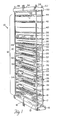
- the electrodeionization apparatus 10 comprises one stage 12 bounded by electrode 9 and electrode 11.
- the stage 12 includes an end plate 13 having an expandable bladder 15 and an inlet 16 for fluid to expand the bladder 15.
- Adjacent the endplate 13 is an endblock 17 to house electrode 9 and provide desired manifolding.
- An electrode spacer 18 is positioned adjacent to the end block 17 and includes a screen 19 which effects turbulent flow of liquid passing through the electrode spacer 18.
- An ion permeable membrane 20 is sealed to the periphery 21 of electrode spacer 18.
- Spacers 22 formed of flexible material include a screen 24. The spacers 22 and screens 24 comprise the concentrating compartments of the elctrodeionization apparatus of this invention.
- the depleting compartment structures of this invention comprise an ion permeable membrane 26, a spacer formed of rigid material 28 and an ion permeable membrane 30.
- the ion permeable membranes 26 and 30 are sealed to the periphery 32 of the spacer 28 on opposite surfaces of the spacer 28.
- Mixed ion exchange resin beads 34 are housed within a central space which includes ribs (not shown) and are retained therein by the membranes 26 and 30.
- Liquid to be purified within stage 12 is passed through at least two units comprising spacer 22 and 28 and membranes 26 and 30.
- the units which comprise spacers 22 and 28 and membranes 26 and 30 are repeated usually between about 5 and 100 times in order to provide reasonable liquid flow through capacity in stage 12.
- An electrode spacer 42 is positioned adjacent the end plate 44 and electrode 11.
- End plate 50 is provided with flexible bladder 52 which is inflated by fluid passing through conduit 54.
- Bolts 56, 58 and 60 as well as a fourth bolt (not shown) extend along the entire length of the apparatus 10 to retain the apparatus elements in place.
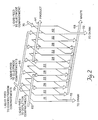
- Liquid to be purified enter inlet 62, passes through depletion compartments 28, is then passed through a second depletion compartment 28 flowing in the compartment 28 and is recovered from outlet 64.
- liquid flow through the depletion compartments can be in one direction in each stage. Also, the liquid can be made to flow through more than two depletion compartments in each stage.
- the liquid effluent from a depletion compartment can be split into multiple stream and then passed through a second set of depletion compartments.
- Concentrating liquid is passed through outlet 66 through concentrating compartments 22 and thence through outlet 68 to drain. Liquid electrolyte is circulated through electrode compartments 19 and 42 from inlets 70 and is discarded to drain through outlets 72.
- the electrode structure is shown which comprises a rigid block 44 and an electrode 11.
- the block 44 is provided with electrolyte feed inlet 82 and electrolyte waste outlet 72.
- Electrode 11 includes a connector 85 which contacts the exterior electrical connection 87 as shown in the detail portion of Figure 5.
- the block 44 includes an inlet 62 and outlet 64 for depletion compartments and inlets 65 and 66 and outlets 63 and 68 for concentration compartments.
- the electrode spacer 67 includes electrolyte inlet 70 and electrolyte outlet 72 and a screen 90 for effecting turbulence of liquid passing therethrough.
- the spacer formed of flexible material e.g. spacer 38
- the spacer formed of flexible material includes a liquid inlet 66 and a liquid outlet 68 which provide liquid communication to the interior of spacer 38 in which is positioned a screen 95 in order to effect turbulent liquid flow.
- the outlet 64 permits passage of liquid into the adjacent depleting compartments and inlet 62 permits liquid removal from the adjacent depleting compartments without admixture of the purified liquid with the liquid in the concentrating compartment formed in spacer 38.
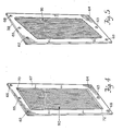
- the depleting compartment comprises a rigid spacer, e.g. spacer 28, and an anion permeable membrane 30 and cation membrane 26.
- the ion exchange materials 34 are housed within subcompartments formed by the membranes 26 and 30, the wall 105 and the ribs 99.
- the membranes 26 and 30 are sealed along their entire length to wall 105 and ribs 99.
- the membranes 26 and 30 are also sealed to the periphery of the rigid spacer 28 so that the individual subcompartments 98 are effectively isolated from each other.
- Liquid to be purified enters inlets 101 and into the subcompartments 98 wherein they are subjected to an electrical voltage in order to pass anions through membrane 30 and cations through membrane 26.
- the purified liquid then passes through outlets 102 and spacer outlet 64 wherein it is collected in accordance with the explanation of Figure 2.
- the liquid to be purified can be pretreated prior to the electrodeionization to remove specific contaminants such as organics.
- a softener-scavenger system can be employed wherein the softener can include a cation exchange resin and/or an anion exchange resin to remove specific ions.
- the scavenger can comprise an anion exchange resin in order to remove foulants that foul the anion resin such as organics, including tannins, humic acids, fulvic acids and lignins.
- the ion exchange resins can be regenerated with brine (NaCl) efficiently and simply.
- Suitable anion permeable membranes include a homogeneous type web supported styrene-divinylbenzene based with sulfonic acid or quarternary ammonium functional groups sold under the identifications CR61-CZL-386 and AR 103-QZL-386 by Ionics Inc.; a heterogeneous type web supported using styrene-divinylbenzene based resins in a polyvinylidene fluoride binder sold under the identifications MC-3470 and MA-3475 by Sybron/ionac; homogeneous type unsupported sulfonated styrene and quarternized vinylbenzylamine grafts of polyethylene sheet sold under the name, Raipore by RAI Research Corporation; a homogeneous type web supported styrene-divinylbenzene based with sulfonic acid or quarternary ammonium functional groups sold under the name Neosepta by Tokuyama Sod
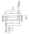
- This example illustrate the improved separation efficiency obtained with the electrodeionization apparatus of this invention utilizing multiple passes through depletion compartments in a separation stage as compared to an electrodeionization apparatus utilizing a single pass through a depletion compartment in a separation stage.
- the first stack contained two 26-inch long dilute cells arranged in parallel and sandwiched between one concentrate spacer and a pair of electrode spacers and electrodes (see Figure 8). Two diluting cells were used in parallel to help minimize possible error.
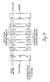
- the second stack contained four 13-inch long dilute cells arranged to obtain two parallel two pass configurations (see Figure 9). the three concentrate spacers were arranged for parallel flow and the cells were bound by electrode spacers and electrodes.
- New membranes and new ion exchange resins were used in both stack assemblies. The two stacks were run simultaneously on the same liquid feed and with the same type power supplies. Data was collected at approximately the same time. Four series of tests were made and the test conditions are described under each series.
- Test conditions Feed 295 umho sodium chloride, temperature 18°C, power source Condor 9 Volt, 1 Amp calculator battery charger (non-variable).
- D1 denotes dilute from 26-inch long flow path
- C1 denotes concentrate from 26-inch long flow path.
- D2 and C2 denote dilute and concentrate from 13-inch long flow path and I i ; 2; E1, E2 denote amperage and voltage respectively.
- the percent water recovery is expressed as R1 and R2.
- Test conditions same as Series A but with a condor 12 volt Amp calculator battery charger (non-variable).
- Test conditions Feed 215 umhos mixture of sodium chloride and sodium bicarbonate at approximately the same milligrams per liter; temperature 18°C; power source 9 Volts, 1 Amp supply used in Series A tests.
- Feed flow rate to each stack was adjusted to 400 ml/min and the applied cell pair voltage was set at 2 volts per cell pair plus 3 volts for the electrode voltage.
- Example IX Same as Example IX at 3 volts per cell pair.
Landscapes
- Chemical & Material Sciences (AREA)
- Chemical Kinetics & Catalysis (AREA)
- Engineering & Computer Science (AREA)
- Water Supply & Treatment (AREA)
- Organic Chemistry (AREA)
- Health & Medical Sciences (AREA)
- Urology & Nephrology (AREA)
- Separation Using Semi-Permeable Membranes (AREA)
- Water Treatment By Electricity Or Magnetism (AREA)
Priority Applications (2)
| Application Number | Priority Date | Filing Date | Title |
|---|---|---|---|
| DE19883879192 DE3879192T2 (de) | 1988-05-31 | 1988-05-31 | Verfahren und vorrichtung zur elektrodesionisation. |
| EP19880108702 EP0346502B1 (de) | 1988-05-31 | 1988-05-31 | Verfahren und Vorrichtung zur Elektrodesionisation |
Applications Claiming Priority (1)
| Application Number | Priority Date | Filing Date | Title |
|---|---|---|---|
| EP19880108702 EP0346502B1 (de) | 1988-05-31 | 1988-05-31 | Verfahren und Vorrichtung zur Elektrodesionisation |
Publications (2)
| Publication Number | Publication Date |
|---|---|
| EP0346502A1 true EP0346502A1 (de) | 1989-12-20 |
| EP0346502B1 EP0346502B1 (de) | 1993-03-10 |
Family
ID=8199014
Family Applications (1)
| Application Number | Title | Priority Date | Filing Date |
|---|---|---|---|
| EP19880108702 Expired - Lifetime EP0346502B1 (de) | 1988-05-31 | 1988-05-31 | Verfahren und Vorrichtung zur Elektrodesionisation |
Country Status (2)
| Country | Link |
|---|---|
| EP (1) | EP0346502B1 (de) |
| DE (1) | DE3879192T2 (de) |
Cited By (5)
| Publication number | Priority date | Publication date | Assignee | Title |
|---|---|---|---|---|
| EP0417506A1 (de) * | 1989-09-08 | 1991-03-20 | Millipore Corporation | Behandlungsverfahren durch elektrische Entionisierung und UV-Licht zur Reinigung von Wasser |
| WO1992011089A1 (en) * | 1990-12-17 | 1992-07-09 | Ionpure Technologies Corporation | Electrodeionization apparatus |
| WO1994006548A1 (en) * | 1992-09-15 | 1994-03-31 | Ionpure Technologies Corporation | Modules for electrodeionization apparatus |
| US5558753A (en) * | 1994-05-20 | 1996-09-24 | U.S. Filter/Ionpure, Inc. | Polarity reversal and double reversal electrodeionization apparatus and method |
| EP1466656A3 (de) * | 2003-04-11 | 2006-10-11 | Millipore Corporation | Vorrichtung zur Elektroentionisierung |
Citations (3)
| Publication number | Priority date | Publication date | Assignee | Title |
|---|---|---|---|---|
| GB877239A (en) * | 1957-12-24 | 1961-09-13 | Permutit Co Ltd | Improvements relating to electrodialytic cells |
| US3291713A (en) * | 1964-05-27 | 1966-12-13 | Ionics | Removal of weakly basic substances from solution by electrodeionization |
| EP0170895B1 (de) * | 1984-07-09 | 1989-03-22 | Millipore Corporation | Vorrichtung und Verfahren zur elektrischen Entionisierung |
-
1988
- 1988-05-31 EP EP19880108702 patent/EP0346502B1/de not_active Expired - Lifetime
- 1988-05-31 DE DE19883879192 patent/DE3879192T2/de not_active Expired - Lifetime
Patent Citations (3)
| Publication number | Priority date | Publication date | Assignee | Title |
|---|---|---|---|---|
| GB877239A (en) * | 1957-12-24 | 1961-09-13 | Permutit Co Ltd | Improvements relating to electrodialytic cells |
| US3291713A (en) * | 1964-05-27 | 1966-12-13 | Ionics | Removal of weakly basic substances from solution by electrodeionization |
| EP0170895B1 (de) * | 1984-07-09 | 1989-03-22 | Millipore Corporation | Vorrichtung und Verfahren zur elektrischen Entionisierung |
Cited By (8)
| Publication number | Priority date | Publication date | Assignee | Title |
|---|---|---|---|---|
| EP0417506A1 (de) * | 1989-09-08 | 1991-03-20 | Millipore Corporation | Behandlungsverfahren durch elektrische Entionisierung und UV-Licht zur Reinigung von Wasser |
| WO1992011089A1 (en) * | 1990-12-17 | 1992-07-09 | Ionpure Technologies Corporation | Electrodeionization apparatus |
| US5316637A (en) * | 1990-12-17 | 1994-05-31 | Ip Holding Company | Electrodeionization apparatus |
| WO1994006548A1 (en) * | 1992-09-15 | 1994-03-31 | Ionpure Technologies Corporation | Modules for electrodeionization apparatus |
| US5558753A (en) * | 1994-05-20 | 1996-09-24 | U.S. Filter/Ionpure, Inc. | Polarity reversal and double reversal electrodeionization apparatus and method |
| US5736023A (en) * | 1994-05-20 | 1998-04-07 | U.S. Filter/Ionpure, Inc. | Polarity reversal and double reversal electrodeionization apparatus and method |
| EP1466656A3 (de) * | 2003-04-11 | 2006-10-11 | Millipore Corporation | Vorrichtung zur Elektroentionisierung |
| US7763157B2 (en) | 2003-04-11 | 2010-07-27 | Millipore Corporation | Electrodeionization device |
Also Published As
| Publication number | Publication date |
|---|---|
| EP0346502B1 (de) | 1993-03-10 |
| DE3879192D1 (de) | 1993-04-15 |
| DE3879192T2 (de) | 1993-08-12 |
Similar Documents
| Publication | Publication Date | Title |
|---|---|---|
| US4931160A (en) | Electrodeionization method and apparatus | |
| US4632745A (en) | Electrodeionization apparatus | |
| US4925541A (en) | Electodeionization apparatus and method | |
| EP0417506B1 (de) | Behandlungsverfahren durch elektrische Entionisierung und UV-Licht zur Reinigung von Wasser | |
| US5154809A (en) | Process for purifying water | |
| USRE35741E (en) | Process for purifying water | |
| US4956071A (en) | Electrodeionization apparatus and module | |
| US4747929A (en) | Depletion compartment and spacer construction for electrodeionization apparatus | |
| US6365023B1 (en) | Electrodeionization process | |
| US5308466A (en) | Electrodeionization apparatus | |
| US4969983A (en) | Apparatus and process for the removal of acidic and basic gases from fluid mixtures using bipolar membranes | |
| EP1034833B1 (de) | Kompartimente für elektrischen Entionisierungsapparat | |
| AU2007297499B2 (en) | Arrangement of ion exchange material within an electrodeionization apparatus | |
| US9422176B2 (en) | Systems and techniques for electrodialysis | |
| JP2002527238A (ja) | 電気脱イオンユニットにおけるスケール発生を防ぐ方法および装置 | |
| JP2865389B2 (ja) | 電気式脱イオン水製造装置とそれに用いる枠体 | |
| WO1997046491A1 (fr) | Procede de production d'eau deionisee par une technique de deionisation electrique | |
| US6998044B2 (en) | Electrophoretic cross-flow filtration and electrodeionization: method for treating effluent waste and apparatus for use therewith | |
| US3577331A (en) | Apparatus and process for effecting changes in solution concentrations | |
| EP0346502B1 (de) | Verfahren und Vorrichtung zur Elektrodesionisation | |
| US4737260A (en) | Membrane stack unit for multi-chamber electrodialysis | |
| JPH01307410A (ja) | 電気脱イオン化方法および装置 | |
| AU2013200835B2 (en) | Arrangement of ion exchange material within an electrodeionization apparatus | |
| Rose et al. | ELECTRODIALYSIS: ION EXCHANGE | |
| HK1189543A (en) | Systems and techniques for electrodialysis |
Legal Events
| Date | Code | Title | Description |
|---|---|---|---|
| PUAI | Public reference made under article 153(3) epc to a published international application that has entered the european phase |
Free format text: ORIGINAL CODE: 0009012 |
|
| AK | Designated contracting states |
Kind code of ref document: A1 Designated state(s): DE FR GB IT NL SE |
|
| 17P | Request for examination filed |
Effective date: 19900523 |
|
| 17Q | First examination report despatched |
Effective date: 19910321 |
|
| RBV | Designated contracting states (corrected) |
Designated state(s): DE FR GB IT |
|
| GRAA | (expected) grant |
Free format text: ORIGINAL CODE: 0009210 |
|
| AK | Designated contracting states |
Kind code of ref document: B1 Designated state(s): DE FR GB IT |
|
| ET | Fr: translation filed | ||
| REF | Corresponds to: |
Ref document number: 3879192 Country of ref document: DE Date of ref document: 19930415 |
|
| ITF | It: translation for a ep patent filed | ||
| PLBE | No opposition filed within time limit |
Free format text: ORIGINAL CODE: 0009261 |
|
| STAA | Information on the status of an ep patent application or granted ep patent |
Free format text: STATUS: NO OPPOSITION FILED WITHIN TIME LIMIT |
|
| 26N | No opposition filed | ||
| REG | Reference to a national code |
Ref country code: GB Ref legal event code: IF02 |
|
| PGFP | Annual fee paid to national office [announced via postgrant information from national office to epo] |
Ref country code: DE Payment date: 20070702 Year of fee payment: 20 |
|
| PGFP | Annual fee paid to national office [announced via postgrant information from national office to epo] |
Ref country code: GB Payment date: 20070525 Year of fee payment: 20 |
|
| PGFP | Annual fee paid to national office [announced via postgrant information from national office to epo] |
Ref country code: IT Payment date: 20070526 Year of fee payment: 20 |
|
| PGFP | Annual fee paid to national office [announced via postgrant information from national office to epo] |
Ref country code: FR Payment date: 20070517 Year of fee payment: 20 |
|
| REG | Reference to a national code |
Ref country code: GB Ref legal event code: PE20 Expiry date: 20080530 |
|
| PG25 | Lapsed in a contracting state [announced via postgrant information from national office to epo] |
Ref country code: GB Free format text: LAPSE BECAUSE OF EXPIRATION OF PROTECTION Effective date: 20080530 |