EP0346338B1 - Sideboard control mechanism - Google Patents
Sideboard control mechanism Download PDFInfo
- Publication number
- EP0346338B1 EP0346338B1 EP88900871A EP88900871A EP0346338B1 EP 0346338 B1 EP0346338 B1 EP 0346338B1 EP 88900871 A EP88900871 A EP 88900871A EP 88900871 A EP88900871 A EP 88900871A EP 0346338 B1 EP0346338 B1 EP 0346338B1
- Authority
- EP
- European Patent Office
- Prior art keywords
- sideboard
- pivoted
- locking
- actuating
- rod
- Prior art date
- Legal status (The legal status is an assumption and is not a legal conclusion. Google has not performed a legal analysis and makes no representation as to the accuracy of the status listed.)
- Expired - Lifetime
Links
Images




Classifications
-
- B—PERFORMING OPERATIONS; TRANSPORTING
- B60—VEHICLES IN GENERAL
- B60P—VEHICLES ADAPTED FOR LOAD TRANSPORTATION OR TO TRANSPORT, TO CARRY, OR TO COMPRISE SPECIAL LOADS OR OBJECTS
- B60P1/00—Vehicles predominantly for transporting loads and modified to facilitate loading, consolidating the load, or unloading
- B60P1/003—Vehicles predominantly for transporting loads and modified to facilitate loading, consolidating the load, or unloading vehicles with loading gates
-
- B—PERFORMING OPERATIONS; TRANSPORTING
- B62—LAND VEHICLES FOR TRAVELLING OTHERWISE THAN ON RAILS
- B62D—MOTOR VEHICLES; TRAILERS
- B62D33/00—Superstructures for load-carrying vehicles
- B62D33/02—Platforms; Open load compartments
- B62D33/023—Sideboard or tailgate structures
- B62D33/027—Sideboard or tailgate structures movable
- B62D33/03—Sideboard or tailgate structures movable by swinging down
Definitions
- the present invention relates to a mechanism for locking and actuating a pivoted sideboard or the like, said mechanism being of the kind set forth in a detailed manner in the preamble of claim 1.
- the known mechanisms of this kind do, however, suffer from considerable drawbacks relating to the installation thereof, since the work with installing two separate locking mechanisms, together with two separate actuating mechanisms and the requisite remote-controlling equipment, demands a great effort of highly qualified personnel, which situation is not made more tolerable by the fact that in many cases the work has to be done out-of-doors during inclement weather.
- the known mechanisms are relatively vulnerable, especially if an actuating mechanism is placed in a highly exposed position at the rear of the vehicle in question, and both this mechanism, the associated locking mechanism as well as the remote-controlling equipment may easily be damaged under the rough operating conditions often encountered by vehicles of the kind presently referred to, namely during work on building and construction sites.
- the present invention is based on the recognition of the fact that the pivoted sideboards being used on modern vehicles of the kind presently referred to exhibit such a high torsional rigidity, that they may readily be actuated by means of one solitary actuating mechanism placed at one of its ends, such as presented as one of the alternatives in the above SE-B-430 405.
- the novel arrangement of the locking mechanism makes it possible to place the remote-controlling means for the locking mechanism at the same end of the pivoted sideboard at which such a solitary actuating mechanism is situated, and in this way long and vulnerable remote-controlling leads to the opposite end of the pivoted sideboard are avoided.
- the ready-to-install unit can e.g. comprise the hydraulic pump necessary for the functioning of the mechanism and the electric drive motor for this pump as well as electrically controlled valves for controlling the actuating mechanism and the locking mechanism or mechanisms, and in that case the work of making the connecting will solely consist in the connection of a number of electrical wires, which may be simplified further by using multi-contact plugs and sockets.
- the ready-to-install unit may in certain cases also comprise the locking mechanism or mechanisms and e.g. the hydraulic conduits for the actuating means for this mechanism or mechanisms.
- the pivoted sideboard already existing being utilized to transmit the locking and unlocking movements from one end of it to the other.
- the mutually cooperating locking engagement means may preferably be constructed with a latching effect, the pivoted sideboard for this purpose being spring loaded in the direction of engagement.
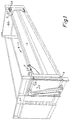
- Figure 1 shows those parts of a load box for a load-carrying vehicle associated with a sideboard 1.
- the sideboard 1 is pivotably supported about an axis 2 shown in Figure 2.
- a locking mechanism 4 is adapted to retain the sideboard 1 in the vertical closing position.
- the locking mechanism 4 comprises a transmission rod 5, which is adapted to transmit locking and unlocking movements from the end of the sideboard 1 closest to the actuating mechanism 3 to the opposite end of the sideboard.
- the sole actuating mechanism 3 is situated on a fixed front board 6.
- the complete box shown in Figure 1 may be adapted to be pivoted in one or a number of directions.
- the actuating mechanism 3 consists of
- the locking mechanism 4 vide especially Figures 2b, 3b and c, and Figures 6 and 7, consists of
- both the cylinder 13 and the cylinder 22 are in their non-actuated state, i.e. the pressure difference across their pistons is insignificant or zero.
- pressure is supplied to the cylinder 22 by means of the control means (not shown), so that the cylinder 22 moves the transmission rod 5 against the force of the spring 23 to the left in Figure 2b, by which the latch block 16 is disengaged from the catch 18, and at the same time the bolt 17 is pulled out of the bolt bush 19.
- the catch 18 is shaped like a reclining U with the open side facing outwards, so that the part of the transmission rod 5 being connected to the latch block 16 may be moved into and out of engagement with the catch 18.
- the latch block 16 comprises a ramp 24 which as shown in Figures 2b, 3b, 3c and 6 extends at an oblique angle away from the center and axis of the transmission rod 5.
- the ramp 24 on the latch block 16 will during the terminal phase of the closing movement - vide Figures 3c and 3b respectively - cause the latch block 16 to move towards the left in Figure 3c and then - vide Figures 3b and 2c respectively - move slidingly past the catch 18 and snap in behind same to the locking position shown in Figures 2b.
- the latch block 16 and the catch 18 comprise mutually cooperating slightly oblique locking engagement surfaces 25 and 26 respectively, which provide a wedge action and thus prevent lost motion between these two components.
- the locking bolt portion 17 of the transmission rod 5 is also retracted to such an extent that it can pass the outermost part of the locking bolt bush 19 without hindrance and then - vide Figure 2b - snap into same at the same time as the latch block 16 snaps in behind the catch 18.
- Figure 8 shows how two mechanisms may be situated symmetrically with one on each side of a load box, while a control unit 37 is placed on the front board 6 between the two actuating mechanisms 3, said control unit 37 in a manner known but not shown containing the requisite power supply and control means, that are connected, partly to the actuating cylinders 13 and 22, partly to the mechanism's sensors (not shown) for indicating the state and position of the mechanism and/or the sideboard 1, and partly the requisite power supply and remote-control leads and conduits, all through suitable hydraulic and electrical conduits and conductors.
- the equipment shown in Figure 8 may preferably be constructed in the form of a complete unit ready for mounting on a front board, further installation work solely comprising placing the transmission rods 5 on or in the sideboards 1 and placing the locking bolt bushes 19 on or in e.g. the rear board, as well as laying any requisite hydraulic and/or electrical conduits and leads.
- Figures 9a, b and c show in a manner roughly corresponding to Figures 2b, 3b and 3c a second exemplary embodiment of the locking mechanism, in this case bearing the reference number 44.
- the locking mechanism 44 comprises a transmission rod 45, in its end pointing left in Figure 9 being permanently connected to a latch bolt 46, and with its end pointing towards the right in Figure 9 being permanently connected to an ejector 47.
- the sideboard 1 is locked against outward movement in the position shown in Figure 9a, partly by the engagement of the latch bolt 46 with an aperture 50 in the front board 6, partly by the engagement between a latch bolt 51 resiliently supported on the rear board 20 and the bore 52, in which the ejector 47 is slidably supported.
- an actuating cylinder 53 secured to the front board 6 is actuated to push an ejector 54 secured to its piston rod into the aperture 50 and thereby press the latch bolt 46 back until the ejector 54 with a collar 55 abuts against the front board 6 (or a fitting secured thereto).
- the actuating cylinder 53 is in a manner corresponding to that of the above-mentioned actuating cylinder 22 adapted to be controlled in coordination with the actuating mechanism 3 substantially in the manner referred to above.
- the latch bolts 46 and 51 have oblique ramps 57 and 58 respectively.
- the transmission rod 45 is returned to the position shown in Figure 9a by means of a spring 59, permanently urging the rod towards the left in Figure 9.
- Figure 9 is purely diagrammatic, and thus this figure does not show any requisite means to ensure that the end of the ejector 47 facing right in Figure 9 is precisely aligned with the end surface of the sideboard 1 when the ejector 54 has pressed the latch bolt 46 out of engagement as shown in Figure 9b.
- the ejector 54 is held in the position shown in figure 9a by a spring 60 placed inside the cylinder 53, so that the cylinder 53 may be constructed as a single-acting cylinder.
- the actuating rod 15 of the actuating mechanism 3 may be connected to the sideboard 1 through a lost-motion mechanism (not shown), which in the initial phase of the movement of the cylinder 13 actuates the locking mechanism 4 or 44 respectively to move the transmission rod 5 or 45 respectively towards the left in Figure 2b or towards the right in Figure 9a respectively, after which stage further movement of the cylinder 13 will be transmitted to the sideboard 1 for moving sane outwardly from the vertical closing position shown in Figure 2.
- a further possibility consists in letting the sideboard itself constitute the transmission member for transmitting locking and unlocking movements from that end of the sideboard, where the actuating mechanism is situated, to the opposite end of the sideboard.
- Such an embodiment may e.g. be realized by letting the sideboard be both pivotably and longitudinally translatably supported on hinges corresponding to the axis 2 in Figure 2a and by constructing mutually cooperating locking engagement means on the two ends of the sideboard and the adjacent parts of the front and back boards, said engagement means being arranged in such a manner that a longitudinal movement of the sideboard in one direction causes unlocking, while a longitudinal movement in the opposite direction causes locking engagement.
- the said mutually cooperating locking engagement means be arranged in such a manner, that they enable a latching effect to take place when the sideboard is being closed, the sideboard for this purpose possibly being spring-loaded in the direction of the latter longitudinal direction, i.e. the locking direction.
Landscapes
- Engineering & Computer Science (AREA)
- Transportation (AREA)
- Mechanical Engineering (AREA)
- Combustion & Propulsion (AREA)
- Chemical & Material Sciences (AREA)
- Lock And Its Accessories (AREA)
- Passenger Equipment (AREA)
- Tables And Desks Characterized By Structural Shape (AREA)
- Toys (AREA)
- Physical Water Treatments (AREA)
- Fuses (AREA)
- Laying Of Electric Cables Or Lines Outside (AREA)
- Handcart (AREA)
- Drawers Of Furniture (AREA)
- Photoreceptors In Electrophotography (AREA)
- Actuator (AREA)
- Color Printing (AREA)
- Liquid Crystal Substances (AREA)
- Patch Boards (AREA)
- Input Circuits Of Receivers And Coupling Of Receivers And Audio Equipment (AREA)
- Electrophonic Musical Instruments (AREA)
- Fittings On The Vehicle Exterior For Carrying Loads, And Devices For Holding Or Mounting Articles (AREA)
- Vehicle Body Suspensions (AREA)
- Body Structure For Vehicles (AREA)
- Forklifts And Lifting Vehicles (AREA)
Abstract
Description
- The present invention relates to a mechanism for locking and actuating a pivoted sideboard or the like, said mechanism being of the kind set forth in a detailed manner in the preamble of
claim 1. - In previously known mechanisms of this kind it has been considered necessary to have a separate locking mechanism for each end of the pivoted sideboard. As an example, the arrangement described in SE-B-430 405 (equivalent to DE-A-3 224 202) may be mentioned. This arrangement comprises a combined actuating and locking mechanism placed at one or both ends of the pivoted sideboard in question, vide p. 4, lines 10-14 (resp. p. 11, last paragraph) in the publication. The known mechanisms of this kind do, however, suffer from considerable drawbacks relating to the installation thereof, since the work with installing two separate locking mechanisms, together with two separate actuating mechanisms and the requisite remote-controlling equipment, demands a great effort of highly qualified personnel, which situation is not made more tolerable by the fact that in many cases the work has to be done out-of-doors during inclement weather. As to the functioning, the known mechanisms are relatively vulnerable, especially if an actuating mechanism is placed in a highly exposed position at the rear of the vehicle in question, and both this mechanism, the associated locking mechanism as well as the remote-controlling equipment may easily be damaged under the rough operating conditions often encountered by vehicles of the kind presently referred to, namely during work on building and construction sites.
- It is on this background the object purpose of the present invention to provide a mechanism of the kind referred to initially, with which mechanism the drawbacks related to above may be remedied or at least reduced, and this object purpose is achieved with a mechanism, according to the present invention exhibiting the arrangement and features set forth in the characterizing clause of
claim 1. - The present invention is based on the recognition of the fact that the pivoted sideboards being used on modern vehicles of the kind presently referred to exhibit such a high torsional rigidity, that they may readily be actuated by means of one solitary actuating mechanism placed at one of its ends, such as presented as one of the alternatives in the above SE-B-430 405. Thus, the novel arrangement of the locking mechanism makes it possible to place the remote-controlling means for the locking mechanism at the same end of the pivoted sideboard at which such a solitary actuating mechanism is situated, and in this way long and vulnerable remote-controlling leads to the opposite end of the pivoted sideboard are avoided.
- The
claims 2 to 6 relate to useful embodiments, especially of the locking mechanism, the efforts of which are explained in more detail in the succeeding detailed portion of the present specification. - With the embodiment set forth in claim 7 it is possible to achieve a further simplification of the installation work, since in many cases it will be sufficient to bolt or weld the mechanism to the part of the vehicle in question and connect the power supply leads and conduits to the vehicle's power supply system. The ready-to-install unit can e.g. comprise the hydraulic pump necessary for the functioning of the mechanism and the electric drive motor for this pump as well as electrically controlled valves for controlling the actuating mechanism and the locking mechanism or mechanisms, and in that case the work of making the connecting will solely consist in the connection of a number of electrical wires, which may be simplified further by using multi-contact plugs and sockets. The ready-to-install unit may in certain cases also comprise the locking mechanism or mechanisms and e.g. the hydraulic conduits for the actuating means for this mechanism or mechanisms.
- With the embodiment set forth in
claim 8 it is possible to omit special remotely controlled actuating means for the locking mechanism, since in this embodiment the locking mechanism is actuated directly from the actuating mechanism in the initial phase of the latter's opening movement. - With the embodiment set forth in claim 9 it is possible to swing the pivoted sideboard right down to the hanging position. With this arrangement it is possible to avoid that material resting on the pivoted sideboard imposes a strain on the actuating mechanism. Another advantage achieved is that the hanging pivoted sideboard does not come in the way of a fork-lift truck used for placing goods on or removing goods from the vehicle's floor.
- With the embodiment set forth in
claim 10 it is possible to achieve further simplification of the mechanism, the pivoted sideboard already existing being utilized to transmit the locking and unlocking movements from one end of it to the other. The mutually cooperating locking engagement means may preferably be constructed with a latching effect, the pivoted sideboard for this purpose being spring loaded in the direction of engagement. - In the following detailed specification the present invention is explained with reference to exemplary embodiments of a mechanism according to the invention, in part shown in a more or less diagrammatic fashion in the drawings, in which
- Figure 1
- is an overall perspective view of the mechanish with associated parts of a vehicle load box,
- Figures 2 to 5
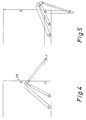
- illustrate the procedure during the disengagement and opening movement of a pivoted sideboard,
- Figure 6 and 7
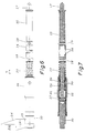
- show details of the locking mechanism in the mechanism shown in figures 1 to 5, in elevation and longitudinal section respectively,
- Figure 8
- shows a ready-to-install unit constructed from two actuating mechanisms of the type shown in Figures 1 to 5 together with associated power supply equipment, and
- Figure 9
- shows a second exemplary embodiment of the locking mechanism in a mechanism according to the invention.
- Figure 1 shows those parts of a load box for a load-carrying vehicle associated with a
sideboard 1. At the edge being lowermost in its vertical closed position as shown, thesideboard 1 is pivotably supported about anaxis 2 shown in Figure 2. By means of ahydraulic actuating mechanism 3 thesideboard 1 may be moved from the vertical closing position mentioned towards various other positions, e.g. in which the sideboard is generally horizontal or depends generally vertically from theaxis 2. A locking mechanism 4 is adapted to retain thesideboard 1 in the vertical closing position. In the exemplary embodiment shown in Figures 1 to 7, the locking mechanism 4 comprises atransmission rod 5, which is adapted to transmit locking and unlocking movements from the end of thesideboard 1 closest to theactuating mechanism 3 to the opposite end of the sideboard. In the exemplary embodiment shown thesole actuating mechanism 3 is situated on afixed front board 6. In a manner well-known, the complete box shown in Figure 1 may be adapted to be pivoted in one or a number of directions. - In the exemplary embodiment shown, the
actuating mechanism 3 consists of - a pivoted arm 7, with a
first part 8 thereof pivotably supported about an axis 9, and with asecond part 10 thereof being set at an angle relative to thefirst part 8 and having twojoint bearings - a double-acting actuating
cylinder 13, the cylinder end of which is pivotably supported about anaxis 14, while its piston end is connected to thesecond part 10 of the pivoted arm 7 through the joint bearing 11, - an
actuating rod 15, with one of its ends being connected to thesecond part 10 of the pivoted arm 7 through the joint bearing 12, and with its other end being secured to one end of thetransmission rod 5, as well as - control and sensing means (not shown).
- The locking mechanism 4, vide especially Figures 2b, 3b and c, and Figures 6 and 7, consists of
- the above-mentioned
transmission rod 5, at its end pointing to the left in Figure 2b being secured to the actuatingrod 15 through alatch block 16, and at its end pointing to the right in Figure 2b being shaped in the form of alocking bolt 17, - a catch (18), which is secured to the
front board 6 and adapted to cooperate with thelatch block 16 in a manner to be explained below, - a locking-
bolt bush 19, which is secured to a fixed member at the end lying to the right in Figure 2b, e.g. arear board 20, and which is adapted to cooperate with the locking-bolt portion 17 of thetransmission rod 5 in a manner to be explained below, - a double-acting actuating mechanism consisting of a single-acting hydraulic actuating
cylinder 22, which is adapted to move thetransmission rod 5 from the right to the left in Figures 2b, 3b, 3c, 6 and 7, against the force from aspring 23 permanently acting upon the transmission rod in a direction in which its locking-bolt portion 17 is maintained in engagement with the locking-bolt bush 19 secured to therear board 20, as well as - connecting means, control means and possibly sensing means (not shown) for the actuating
cylinder 22 and/or components being actuated by same. - In the position of rest, in which - vide Figure 2 - the
sideboard 1 is in its vertical closing position and is locked in this position by the locking mechanism 4, both thecylinder 13 and thecylinder 22 are in their non-actuated state, i.e. the pressure difference across their pistons is insignificant or zero. When thesideboard 1 is to be opened by swinging outwards about theaxis 2 in a clockwise direction as viewed in Figure 2a, pressure is supplied to thecylinder 22 by means of the control means (not shown), so that thecylinder 22 moves thetransmission rod 5 against the force of thespring 23 to the left in Figure 2b, by which thelatch block 16 is disengaged from thecatch 18, and at the same time thebolt 17 is pulled out of thebolt bush 19. At this stage thesideboard 1 is free to be moved outwards by contracting thecylinder 13, so that the arm 7 is turned clockwise in Figure 2a and thus moves theactuating rod 15 and the upper part of thesideboard 1 towards the right in Figure 2a. This movement may be continued as far as desired in each case, e.g. to the horizontal position shown in Figure 4 or the depending vertical position shown in Figure 5. It will be seen especially from Figure 5 that the angular shape of the pivoted arm 7 contributes to making the movement to the depending position shown in Figure 5 possible. - As will be seen from Figures 3b and c as well as Figures 4 and 5, the
catch 18 is shaped like a reclining U with the open side facing outwards, so that the part of thetransmission rod 5 being connected to thelatch block 16 may be moved into and out of engagement with thecatch 18. - When the
sideboard 1 has been moved outwardly to such an extend - vide Figures 3b and c - that thelatch block 16 has been disengaged from thecatch 18, the pressure in thecylinder 22 is released, whereupon thespring 23 moves thetransmission rod 5 towards the right in Figures 3b and c. - The
latch block 16 comprises aramp 24 which as shown in Figures 2b, 3b, 3c and 6 extends at an oblique angle away from the center and axis of thetransmission rod 5. When thesideboard 1 is moved from an open position to the closed position shown in Figure 2 by means of theactuating mechanism 3, i.e. by actuating thecylinder 13 in a direction opposite to the previous one, theramp 24 on thelatch block 16 will during the terminal phase of the closing movement - vide Figures 3c and 3b respectively - cause thelatch block 16 to move towards the left in Figure 3c and then - vide Figures 3b and 2c respectively - move slidingly past thecatch 18 and snap in behind same to the locking position shown in Figures 2b. In the exemplary embodiment shown thelatch block 16 and thecatch 18 comprise mutually cooperating slightly obliquelocking engagement surfaces transmission rod 5 is moved from the right towards the left in Figure 3c and 3b respectively, thelocking bolt portion 17 of thetransmission rod 5 is also retracted to such an extent that it can pass the outermost part of thelocking bolt bush 19 without hindrance and then - vide Figure 2b - snap into same at the same time as thelatch block 16 snaps in behind thecatch 18. At this point it should be observed that during the closing movement it is not necessary to actuate thecylinder 22 of the locking mechanism 4. - An example of the more detailed construction of the
transmission rod 5 and the means cooperating therewith is shown in Figures 6 and 7. As will be seen from this Figure, therod 5 is divided into four mutually connected parts by means of threearticulation axes - a
latch block carrier 30, which is connected to theactuating rod 15 not shown in Figure 6 to thelatch block 16 shown only in figure 6, - a
piston rod 31 for thepiston 32 movable in theactuating cylinder 22, the right hand side of which piston may be acted upon by pressure fluid introduced through abore 33, saidrod 31 in its end facing towards the right in Figures 6 and 7 cooperating with thespring 23 referred to above in the manner likewise referred to above, - a connecting
piece 34, as well as - the above-mentioned
locking bolt 17 being slidable in aslide bush 35, which together with asupport bush 36 enclosing and supporting theactuating cylinder 22 is secured to thesideboard 1 at the edge of same being uppermost in the closing position, in a manner not shown. - Figure 8 shows how two mechanisms may be situated symmetrically with one on each side of a load box, while a
control unit 37 is placed on thefront board 6 between the twoactuating mechanisms 3, saidcontrol unit 37 in a manner known but not shown containing the requisite power supply and control means, that are connected, partly to theactuating cylinders sideboard 1, and partly the requisite power supply and remote-control leads and conduits, all through suitable hydraulic and electrical conduits and conductors. The equipment shown in Figure 8 may preferably be constructed in the form of a complete unit ready for mounting on a front board, further installation work solely comprising placing thetransmission rods 5 on or in thesideboards 1 and placing the lockingbolt bushes 19 on or in e.g. the rear board, as well as laying any requisite hydraulic and/or electrical conduits and leads. - Figures 9a, b and c show in a manner roughly corresponding to Figures 2b, 3b and 3c a second exemplary embodiment of the locking mechanism, in this case bearing the
reference number 44. In the same manner as the locking mechanism 4 referred to above, thelocking mechanism 44 comprises atransmission rod 45, in its end pointing left in Figure 9 being permanently connected to a latch bolt 46, and with its end pointing towards the right in Figure 9 being permanently connected to an ejector 47. - The
sideboard 1, the inward movement of which is limited by twostops aperture 50 in thefront board 6, partly by the engagement between a latch bolt 51 resiliently supported on therear board 20 and thebore 52, in which the ejector 47 is slidably supported. When thesideboard 1 is to be moved from the position shown in Figure 9a to the one shown in Figure 9c, anactuating cylinder 53 secured to thefront board 6 is actuated to push anejector 54 secured to its piston rod into theaperture 50 and thereby press the latch bolt 46 back until theejector 54 with acollar 55 abuts against the front board 6 (or a fitting secured thereto). - This action disengages the latch bolt 46 from the
aperture 50, so that it no longer constitutes a hindrance for moving thesideboard 1 outwards. Simultaneously with the movement of the latch bolt 46 from the position shown in Figure 9a to the one shown in Figure 9b the ejector 47 is moved to a position, in which its end surface pointing towards the right in the Figure is aligned with the end surface on the sideboard 1 (or on a corresponding fitting), by which the latch bolt 51 supported by aleaf spring 56 is pressed out of its locking engagement, and now thesideboard 1 may be moved from the position shown in Figure 9b to the one in Figure 9c and further to positions corresponding e.g. to the ones shown in figures 4 and 5 by means of theactuating mechanism 3 not shown in this Figure (or an equivalent actuating mechanism). - The
actuating cylinder 53 is in a manner corresponding to that of the above-mentionedactuating cylinder 22 adapted to be controlled in coordination with theactuating mechanism 3 substantially in the manner referred to above. Thus, when thesideboard 1 is to be moved from the open position shown in Figure 9c to the closed position shown in Figure 9a, it is not necessary to actuate thecylinder 53, since the two latch bolts 46 and 51 are pressed back during the movement towards the closed position in the same manner as the latch bolt in an ordinary door lock. For this purpose, the latch bolts 46 and 51 haveoblique ramps transmission rod 45 is returned to the position shown in Figure 9a by means of a spring 59, permanently urging the rod towards the left in Figure 9. - As previously mentioned, Figure 9 is purely diagrammatic, and thus this figure does not show any requisite means to ensure that the end of the ejector 47 facing right in Figure 9 is precisely aligned with the end surface of the
sideboard 1 when theejector 54 has pressed the latch bolt 46 out of engagement as shown in Figure 9b. Such an alignment could be ensured by placinc mutually cooperating abutment means on the ejector 47 and the right hand end of thesideboard 1 for ensuring the correct alignment position, by making thetransmission rod 45 slightly resilient in the longitudinal direction, and by shaping the latch block 47 and the means cooperating therewith in such a manner, that the extent of the movements of the latch block 46 from the locking position to the release position shown in Figure 9b is somewhat greater than the requisite movement of the ejector 47. By this arrangement, when the latch bolt 46 is pressed back by theejector 54, thetransmission rod 45 will first move the ejector 47 into abutment in the correct alignment position, whereupon any further movement of the latch bolt 46 will be taken up by the resiliency of the transmission rod 45 (such an arrangement is not shown in the drawings, but persons skilled in the art will be able to construct the requisite mechanisms without further guidance). - Normally, the
ejector 54 is held in the position shown in figure 9a by a spring 60 placed inside thecylinder 53, so that thecylinder 53 may be constructed as a single-acting cylinder. - It is also within the scope of the present invention according to a known principle to let the
actuating cylinder 13 serve both theactuating mechanism 3 and thelocking mechanism 4 or 44. For this purpose the actuatingrod 15 of theactuating mechanism 3 may be connected to thesideboard 1 through a lost-motion mechanism (not shown), which in the initial phase of the movement of thecylinder 13 actuates thelocking mechanism 4 or 44 respectively to move thetransmission rod cylinder 13 will be transmitted to thesideboard 1 for moving sane outwardly from the vertical closing position shown in Figure 2. - A further possibility (not shown) consists in letting the sideboard itself constitute the transmission member for transmitting locking and unlocking movements from that end of the sideboard, where the actuating mechanism is situated, to the opposite end of the sideboard. Such an embodiment may e.g. be realized by letting the sideboard be both pivotably and longitudinally translatably supported on hinges corresponding to the
axis 2 in Figure 2a and by constructing mutually cooperating locking engagement means on the two ends of the sideboard and the adjacent parts of the front and back boards, said engagement means being arranged in such a manner that a longitudinal movement of the sideboard in one direction causes unlocking, while a longitudinal movement in the opposite direction causes locking engagement. In the same manner as the parts of the locking mechanism described above, the said mutually cooperating locking engagement means be arranged in such a manner, that they enable a latching effect to take place when the sideboard is being closed, the sideboard for this purpose possibly being spring-loaded in the direction of the latter longitudinal direction, i.e. the locking direction.
Claims (10)
- A mechanism for locking and actuating a vehicle sideboard (1) or the like being pivotably supported about an axis (2) generally parallel to the associated vehicle floor, said mechanism being of the kind comprisinga) an actuating mechanism (3) secured to a non-pivoted board (6) adjacent to the pivoted sideboard (1) and having an actuating member (15) connected to the pivoted sideboard (1) at a point distant from said axis (2), andb) a locking mechanism (4;44) adapted to retain the pivoted sideboard (1) in the closing position (Figure 2;9a) by locking it to an adjacent non-pivoted board (6,20) or other means fixed in relation to said vehicle floor,
characterized inc) that the locking mechanism (4;44) comprises a transmission member (5;45) adapted to transmit locking and unlocking movements from an actuating member (22;53) adjacent to a first part (16,18;46,50) of the locking mechanism placed at a first end of the pivoted sideboard (1) closest to said actuating mechanism (3) to a second part (17,19;51,52) of the locking mechanism positioned at the opposite other end of the pivoted sideboard. - A mechanism according to claim 1, characterized ina) that the transmission member consists of a rod (5) slidable in the longitudinal direction of the pivoted sideboard (1), the end of which positioned at said other end of the pivoted sideboard comprises a locking bolt (17) being urged towards locking engagement with a locking-bolt bush (19) permanently connected to said vehicle floor by a spring (23), the end of said rod (5) positioned at the said first end of the pivoted sideboard being connected to a latch block (16) with a ramp (24) facing the center of the rod (5), said latch block (16) in the closing position of the pivoted sideboard being urged into engagement with a catch (18) permanently connected to said vehicle's floor by said spring (23),b) that the end of said rod (5) positioned closest to said first end is connected to the actuating member (15) of the actuating mechanism (3), said actuating member (15) being connected to the remaining parts of the actuating mechanism in such a manner, that it may be moved parallel to the longitudinal direction of the rod (5) to a sufficient extent that the locking bolt (17) can be moved out of engagement with the locking-bolt bush (19) and the latch block (16) can be moved out of engagement with the catch (18), andc) that said rod (5) is connected to another actuating member (22), by means of which it may be moved against the force exerted by said spring (23), whereasd) the actuating means or the actuating mechanism (3) for the pivoted sideboard (1) and the actuating member (22) for the rod (5) are controlled in such a manner,d1) that when the pivoted sideboard (1) is to be moved from the closing position (Figure 2) to an open position (Figures 3a, 3c, 4 and 5), the actuating member (22) of the rod (5) is first actuated until the rod (5) has moved the latch block (16) and the locking bolt (17) out of locking engagement with the catch (18) and the locking-bolt bush (19) respectively, whereupon the actuating mechanism (3) of the pivoted sideboard is actuated to move the pivoted sideboard (1) away from the closing position to the open position, andd2) that when the pivoted sideboard is to be moved from the open position to the closed position, only the actuating mechanism (3) for the pivoted sideboard is actuated to move the pivoted sideboard to the closing position, wherease) the actuating member (22) of the rod (5) and/or its control means is/are arranged in such a manner, that it/they does/do not prevent that longitudinal movement of the rod (5) caused by the engagement between the ramp (24) on the latch block (16) and the catch (18) during the terminal phase of the closing movement (Figures 3c to 3b).
- A mechanism according to claim 2, characterized in that the actuating member for the rod is constituted by a pressure fluid cylinder (22).
- A mechanism according to claim 3, characterized in that the pressure fluid cylinder (22) is thus placed in or on the pivoted sideboard (1), that its piston rod constitutes a part of the transmission rod (5).
- A mechanism according to claim 1, characterized ina) that the transmission member consists of a rod (45), the end of which positioned at the said first end of the pivoted sideboard (1) is fixedly connected to a latch bolt (46), which in the locking position (Figure 9a) of the rod (45) is held in engagement with an aperture (50) in a part (6) fixedly connected to said vehicle floor by a spring (59) acting on said rod (45), said rod (45) in its opposite end being connected to an ejector (47) adapted to cooperate with a latch bolt (51) resiliently (56) connected to said vehicle floor, said latch bolt (51) in the locking position (Figure 9a) engaging an aperture (52) in the pivoted sideboard (1) or a member connected thereto, andb) that the actuating means of the locking mechanism (44) adapted for the unlocking movement thereof comprise an ejector (54) slidably supported in means connected to said vehicle floor, said ejector (54) being adapted to penetrate sufficiently far into the said aperture (50) in the part (6) to terminate the locking engagement of the first-mentioned latch bolt (46) with the said aperture (50), whereasc) the rod (45) is arranged and dimensioned in such a manner relative to the members cooperating therewith, that when the last-mentioned ejector (54) has entered the aperture (50) for termination of the locking engagement of the first latch bolt (46) with the aperture (50), the first-mentioned ejector (47) has simultaneously moved outwardly through the said aperture (52) in the pivoted sideboard (1) to such an extent, that it terminates the locking engagement of the latch bolt (51) cooperating therewith with the aperture (52).
- A mechanism according to claim 5, characterized in that the last-mentioned ejector (45) is connected to the piston rod in an actuating cylinder (53) and comprises an abutment (55) for limiting its depth of penetration.
- A mechanism according to any one or any of the claims 1 to 6, characterized in that the actuating mechanism (3), possibly two such mechanisms in a symmetrical arrangement (Figure 8) with associated power supply and control means (37) and possibly sensing means, is constructed as a ready-made unit for mounting on a board fixedly connected to a vehicle floor, e.g. a frontboard (6).
- A mechanism according to any one or any of the claims 1 to 7, characterized in that the locking mechanism is adapted to be actuated by the actuating mechanism for the pivoted sideboard, whereas for this purpose a lost-motion connection is inserted between the actuating mechanism and the pivoted sideboard, the lost-motion movement of which is transmitted to the locking mechanism through suitable means, all in such a manner, that when the actuating mechanism is actuated to open the pivoted sideboard, the initial movement thereof causes a lost-motion movement in the lost-motion mechanism again causing an actuation of the locking mechanism to its non-locking state, whereupon when the lost-motion movement is completed, the continued movement of the actuating mechanism is transmitted to the pivoted sideboard for opening same, whereas the lost-motion mechanism and/or the locking mechanism is/are further arranged and/or mutually connected in such a manner, that during oppositely directed movement the locking mechanism does not prevent the movement of the pivoted sideboard towards the closed position.
- A mechanism according to any one or any of the claims 1 to 8 and in which said axis (2) is generally in plane alignment with the associated vehicle floor, characterized in that the actuating mechanism (3) for each pivoted sideboard is adapted to move the pivoted sideboard between the substantially vertical closing position (Figure 2a) and at least one position (Figure 3a, 4 and 5), of which one (Figure 5) is situated substantially 180° from the vertical closing position.
- A mechanism according to any one or any of the claims 1 and 7 to 9, characterized in that the transmission member is constituted by the pivoted sideboard proper, for this purpose being supported both pivotably about a longitudinal axis and translatably substantially in the longitudinal direction of this axis, whereas mutually cooperating locking engagement means are placed on both ends of the pivoted and translatable sideboard as well as on parts fixedly connected to the vehicle floor, said mutually cooperating locking engagement means being thus arranged, that they are disengaged from each other by movement of the pivoted and translatable sideboard in a first longitudinal direction and re-engage each other by movement in the opposite direction.
Priority Applications (1)
| Application Number | Priority Date | Filing Date | Title |
|---|---|---|---|
| AT88900871T ATE81624T1 (en) | 1987-12-14 | 1987-12-14 | CONTROL MECHANISM FOR CAR SIDE FLAPS. |
Applications Claiming Priority (1)
| Application Number | Priority Date | Filing Date | Title |
|---|---|---|---|
| PCT/DK1987/000154 WO1989005749A1 (en) | 1987-12-14 | 1987-12-14 | Sideboard control mechanism |
Publications (2)
| Publication Number | Publication Date |
|---|---|
| EP0346338A1 EP0346338A1 (en) | 1989-12-20 |
| EP0346338B1 true EP0346338B1 (en) | 1992-10-21 |
Family
ID=8153429
Family Applications (1)
| Application Number | Title | Priority Date | Filing Date |
|---|---|---|---|
| EP88900871A Expired - Lifetime EP0346338B1 (en) | 1987-12-14 | 1987-12-14 | Sideboard control mechanism |
Country Status (10)
| Country | Link |
|---|---|
| US (1) | US5022696A (en) |
| EP (1) | EP0346338B1 (en) |
| JP (1) | JPH02502618A (en) |
| AT (1) | ATE81624T1 (en) |
| AU (1) | AU610123B2 (en) |
| DE (1) | DE3782345T2 (en) |
| DK (1) | DK166814B1 (en) |
| FI (1) | FI893801A0 (en) |
| NO (1) | NO168347C (en) |
| WO (1) | WO1989005749A1 (en) |
Families Citing this family (4)
| Publication number | Priority date | Publication date | Assignee | Title |
|---|---|---|---|---|
| US6695390B2 (en) * | 2001-08-17 | 2004-02-24 | Anacleto Matteo Bucco Morello | Apparatus for actuating a side door in a cargo vehicle |
| DE102013103195B4 (en) * | 2013-03-28 | 2019-05-23 | Menke-Janzen Besitzgesellschaft mbH & Co. KG | transport vehicle |
| US9834125B2 (en) * | 2015-12-22 | 2017-12-05 | Altec Industries, Inc. | Telescoping pole rack |
| WO2022031987A1 (en) * | 2020-08-05 | 2022-02-10 | Obrien Gene | Improved ramp assembly |
Citations (1)
| Publication number | Priority date | Publication date | Assignee | Title |
|---|---|---|---|---|
| AT329982B (en) * | 1971-12-20 | 1976-06-10 | Marte Ohg Schmiede Fahrzeugbau | SWIVELING BOARD |
Family Cites Families (11)
| Publication number | Priority date | Publication date | Assignee | Title |
|---|---|---|---|---|
| US1740755A (en) * | 1928-02-11 | 1929-12-24 | George L Wackerow | End-gate construction |
| SE391898B (en) * | 1974-01-17 | 1977-03-07 | Nordberg Carl Eric Bertil | FOLDABLE LIMB FOR A VEHICLE FLAK WITH A MANUVER DEVICE FOR HANDLING HANDLING |
| DE2417882A1 (en) * | 1974-04-11 | 1975-10-30 | Andreas Wagner | Hydraulic operating mechanism for motor vehicles - has double hydraulic cylinder fitting in hollow end stanchion in vehicle superstructure |
| DK150339C (en) * | 1974-05-21 | 1987-12-14 | Jan Moeller | MECHANISM FOR LOADING AND MANUALING A SWINGABLE Wagon Page |
| DE2512972A1 (en) * | 1975-03-24 | 1976-10-07 | Ludwig Winter | Tipper with non jamming flap - has hinges set flat along tipping direction and with spring link in operating levers |
| BE840135A (en) * | 1975-04-18 | 1976-07-16 | DEVICE FOR OPENING AND CLOSING THE SIDE PLATE OF THE LOADING BOX OF A MOTOR VEHICLE IN THE UNLOADED STATE | |
| JPS5320225A (en) * | 1976-08-05 | 1978-02-24 | Shin Meiwa Ind Co Ltd | Side-gate locking device for truck vehicle or other |
| SE430405B (en) * | 1981-05-15 | 1983-11-14 | Gunnar Ellert | Locking device for the automatic locking and releasing of a manoeuvrable flap, for example a door in a chip truck or a truck for transporting solid material |
| SU1221011A1 (en) * | 1984-11-29 | 1986-03-30 | Всесоюзный Научно-Исследовательский И Проектный Институт По Организации,Экономике И Технологии Материально-Технического Снабжения Сельского Хозяйства | Vehicle body |
| JPS619330A (en) * | 1985-02-07 | 1986-01-16 | Oshima Kamotsu Kk | Hood opening and closing mechanism in truck |
| US4826237A (en) * | 1988-02-18 | 1989-05-02 | Rugby Manufacturing Co. | Dump body with self-cleaning, fold down side doors |
-
1987
- 1987-12-14 WO PCT/DK1987/000154 patent/WO1989005749A1/en not_active Ceased
- 1987-12-14 FI FI893801A patent/FI893801A0/en not_active IP Right Cessation
- 1987-12-14 DE DE8888900871T patent/DE3782345T2/en not_active Expired - Fee Related
- 1987-12-14 AT AT88900871T patent/ATE81624T1/en not_active IP Right Cessation
- 1987-12-14 AU AU11552/88A patent/AU610123B2/en not_active Ceased
- 1987-12-14 JP JP63500997A patent/JPH02502618A/en active Pending
- 1987-12-14 EP EP88900871A patent/EP0346338B1/en not_active Expired - Lifetime
- 1987-12-14 US US07/382,643 patent/US5022696A/en not_active Expired - Fee Related
-
1989
- 1989-08-11 NO NO89893247A patent/NO168347C/en unknown
- 1989-08-11 DK DK396789A patent/DK166814B1/en not_active IP Right Cessation
Patent Citations (1)
| Publication number | Priority date | Publication date | Assignee | Title |
|---|---|---|---|---|
| AT329982B (en) * | 1971-12-20 | 1976-06-10 | Marte Ohg Schmiede Fahrzeugbau | SWIVELING BOARD |
Also Published As
| Publication number | Publication date |
|---|---|
| FI893801A7 (en) | 1989-08-11 |
| JPH02502618A (en) | 1990-08-23 |
| DE3782345T2 (en) | 1993-05-19 |
| DK166814B1 (en) | 1993-07-19 |
| NO168347B (en) | 1991-11-04 |
| DK396789D0 (en) | 1989-08-11 |
| FI893801A0 (en) | 1989-08-11 |
| AU1155288A (en) | 1989-07-19 |
| NO893247L (en) | 1989-08-14 |
| EP0346338A1 (en) | 1989-12-20 |
| NO168347C (en) | 1992-02-12 |
| ATE81624T1 (en) | 1992-11-15 |
| US5022696A (en) | 1991-06-11 |
| DK396789A (en) | 1989-08-11 |
| AU610123B2 (en) | 1991-05-16 |
| DE3782345D1 (en) | 1992-11-26 |
| NO893247D0 (en) | 1989-08-11 |
| WO1989005749A1 (en) | 1989-06-29 |
Similar Documents
| Publication | Publication Date | Title |
|---|---|---|
| US6470719B2 (en) | Dirt-free handle for the opening of trunk lids of motor vehicles | |
| CA1251809A (en) | Apparatus and method for connecting and exchanging remote manipulable elements to a central control unit | |
| US4613271A (en) | Universal device to empty different-style garbage containers | |
| US4660654A (en) | Implement wing frame folding apparatus with automatically pivoted biased latch | |
| US9226438B2 (en) | Device for coupling a loader connecting mast to a connecting frame | |
| DE2501798C3 (en) | Swiveling truck drop side | |
| CA2600398A1 (en) | Powered coupling of attachment hydraulics | |
| CA2149254A1 (en) | Multiple Lock Assembly | |
| EP0382073A1 (en) | Quick-attaching mechanism | |
| US5022696A (en) | Sideboard control mechanism | |
| EP0733505A1 (en) | Motor vehicle with foldable roof, and foldable roof for such a motor vehicle | |
| US3539203A (en) | Draft hook latch | |
| US6279853B1 (en) | Aircraft undercarriage lock mechanism | |
| US5642785A (en) | Implement coupling for excavators or loaders | |
| GB2207118A (en) | Grapple actuated by single hydraulic cylinder | |
| US5084939A (en) | Door dampening assembly | |
| GB2193753A (en) | Cylinder lock/actuator subassembly | |
| EP0894920A1 (en) | Lock for a vehicle door | |
| US4796929A (en) | Closure latch control mechanism | |
| CA2279169C (en) | Parking stand for tractor front end loader | |
| CA2739531A1 (en) | Coupler | |
| GB2182834A (en) | Tractor-implement coupling | |
| US6220112B1 (en) | Throttle controlled transmission lockout | |
| US6546595B2 (en) | Hinge | |
| EP0177473B1 (en) | Device for detachably mounting a post to a vehicle platform and a flap or the like to the post |
Legal Events
| Date | Code | Title | Description |
|---|---|---|---|
| PUAI | Public reference made under article 153(3) epc to a published international application that has entered the european phase |
Free format text: ORIGINAL CODE: 0009012 |
|
| AK | Designated contracting states |
Kind code of ref document: A1 Designated state(s): AT BE CH DE FR GB IT LI LU NL SE |
|
| 17P | Request for examination filed |
Effective date: 19891212 |
|
| 17Q | First examination report despatched |
Effective date: 19910315 |
|
| GRAA | (expected) grant |
Free format text: ORIGINAL CODE: 0009210 |
|
| AK | Designated contracting states |
Kind code of ref document: B1 Designated state(s): AT BE CH DE FR GB IT LI LU NL SE |
|
| PG25 | Lapsed in a contracting state [announced via postgrant information from national office to epo] |
Ref country code: IT Free format text: LAPSE BECAUSE OF FAILURE TO SUBMIT A TRANSLATION OF THE DESCRIPTION OR TO PAY THE FEE WITHIN THE PRE;WARNING: LAPSES OF ITALIAN PATENTS WITH EFFECTIVE DATE BEFORE 2007 MAY HAVE OCCURRED AT ANY TIME BEFORE 2007. THE CORRECT EFFECTIVE DATE MAY BE DIFFERENT FROM THE ONE RECORDED.SCRIBED TIME-LIMIT Effective date: 19921021 Ref country code: AT Effective date: 19921021 Ref country code: NL Effective date: 19921021 Ref country code: FR Effective date: 19921021 Ref country code: BE Effective date: 19921021 |
|
| REF | Corresponds to: |
Ref document number: 81624 Country of ref document: AT Date of ref document: 19921115 Kind code of ref document: T |
|
| REF | Corresponds to: |
Ref document number: 3782345 Country of ref document: DE Date of ref document: 19921126 |
|
| PG25 | Lapsed in a contracting state [announced via postgrant information from national office to epo] |
Ref country code: LU Free format text: LAPSE BECAUSE OF NON-PAYMENT OF DUE FEES Effective date: 19921231 |
|
| EN | Fr: translation not filed | ||
| NLV1 | Nl: lapsed or annulled due to failure to fulfill the requirements of art. 29p and 29m of the patents act | ||
| PLBE | No opposition filed within time limit |
Free format text: ORIGINAL CODE: 0009261 |
|
| STAA | Information on the status of an ep patent application or granted ep patent |
Free format text: STATUS: NO OPPOSITION FILED WITHIN TIME LIMIT |
|
| 26N | No opposition filed | ||
| EAL | Se: european patent in force in sweden |
Ref document number: 88900871.0 |
|
| PGFP | Annual fee paid to national office [announced via postgrant information from national office to epo] |
Ref country code: GB Payment date: 19971212 Year of fee payment: 11 |
|
| PGFP | Annual fee paid to national office [announced via postgrant information from national office to epo] |
Ref country code: DE Payment date: 19980227 Year of fee payment: 11 |
|
| PG25 | Lapsed in a contracting state [announced via postgrant information from national office to epo] |
Ref country code: GB Free format text: LAPSE BECAUSE OF NON-PAYMENT OF DUE FEES Effective date: 19981214 |
|
| GBPC | Gb: european patent ceased through non-payment of renewal fee |
Effective date: 19981214 |
|
| PG25 | Lapsed in a contracting state [announced via postgrant information from national office to epo] |
Ref country code: DE Free format text: LAPSE BECAUSE OF NON-PAYMENT OF DUE FEES Effective date: 19991001 |
|
| PGFP | Annual fee paid to national office [announced via postgrant information from national office to epo] |
Ref country code: SE Payment date: 19991221 Year of fee payment: 13 |
|
| PGFP | Annual fee paid to national office [announced via postgrant information from national office to epo] |
Ref country code: CH Payment date: 20000124 Year of fee payment: 13 |
|
| PG25 | Lapsed in a contracting state [announced via postgrant information from national office to epo] |
Ref country code: SE Free format text: LAPSE BECAUSE OF NON-PAYMENT OF DUE FEES Effective date: 20001215 |
|
| PG25 | Lapsed in a contracting state [announced via postgrant information from national office to epo] |
Ref country code: CH Free format text: LAPSE BECAUSE OF NON-PAYMENT OF DUE FEES Effective date: 20001231 Ref country code: LI Free format text: LAPSE BECAUSE OF NON-PAYMENT OF DUE FEES Effective date: 20001231 |
|
| EUG | Se: european patent has lapsed |
Ref document number: 88900871.0 |
|
| REG | Reference to a national code |
Ref country code: CH Ref legal event code: PL |