EP0346313A1 - Hydraulic actuator - Google Patents
Hydraulic actuator Download PDFInfo
- Publication number
- EP0346313A1 EP0346313A1 EP89850187A EP89850187A EP0346313A1 EP 0346313 A1 EP0346313 A1 EP 0346313A1 EP 89850187 A EP89850187 A EP 89850187A EP 89850187 A EP89850187 A EP 89850187A EP 0346313 A1 EP0346313 A1 EP 0346313A1
- Authority
- EP
- European Patent Office
- Prior art keywords
- guiding path
- rudder stock
- wings
- hub
- lip
- Prior art date
- Legal status (The legal status is an assumption and is not a legal conclusion. Google has not performed a legal analysis and makes no representation as to the accuracy of the status listed.)
- Granted
Links
Images
Classifications
-
- B—PERFORMING OPERATIONS; TRANSPORTING
- B63—SHIPS OR OTHER WATERBORNE VESSELS; RELATED EQUIPMENT
- B63H—MARINE PROPULSION OR STEERING
- B63H25/00—Steering; Slowing-down otherwise than by use of propulsive elements; Dynamic anchoring, i.e. positioning vessels by means of main or auxiliary propulsive elements
- B63H25/06—Steering by rudders
- B63H25/08—Steering gear
- B63H25/14—Steering gear power assisted; power driven, i.e. using steering engine
- B63H25/26—Steering engines
- B63H25/28—Steering engines of fluid type
- B63H25/30—Steering engines of fluid type hydraulic
-
- F—MECHANICAL ENGINEERING; LIGHTING; HEATING; WEAPONS; BLASTING
- F15—FLUID-PRESSURE ACTUATORS; HYDRAULICS OR PNEUMATICS IN GENERAL
- F15B—SYSTEMS ACTING BY MEANS OF FLUIDS IN GENERAL; FLUID-PRESSURE ACTUATORS, e.g. SERVOMOTORS; DETAILS OF FLUID-PRESSURE SYSTEMS, NOT OTHERWISE PROVIDED FOR
- F15B15/00—Fluid-actuated devices for displacing a member from one position to another; Gearing associated therewith
- F15B15/08—Characterised by the construction of the motor unit
- F15B15/12—Characterised by the construction of the motor unit of the oscillating-vane or curved-cylinder type
Definitions
- the present invention is related to a wing actuator for turning movement of a spindle, such as a rudder stock, according to the preamble of the claims.
- Actuators for turning movement of rudder stocks are known in many different embodiments, as mechanical as well as hydraulic devices, of which a majority is designed for rectilinear movement of the actuator. In such cases the force transferred to the rudder stock is dependent on the position of the rudder stock in relation to the transmission devices for the actuator. Also known, however, are hydraulical actuators avoiding the aforementioned disadvantage in providing a hydraulic cylinder arranged as a torus shaped guiding path around the rudder stock. The transmission of the forces from the hydraulic fluid in the guiding path, to a turning movement of the rudder stock is, however, circumstantial and involves several single parts, making the embodiment expensive and to a certain extent decreasing the accuracy of the movement.
- the rudder stock is, additionally to a turning movement, undertaking an edging movement due to the forces against the rudder, which forces will bend the rudder stock between upper and lower bearings. Due to this fact the rudder stock from time to time will move out of its ideal position where the axis of the rudder stock is aligned with the axis through upper and lower bearings.
- An actuator for turning movement of the rudder stock therefore must be able to adapt this movement of the rudder stock and ensure that the function of the actuator not substantially is influenced when the rudder stock is moved out of its normal position.
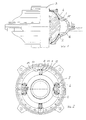
- Fig. 1 discloses a side view, partly in section, of the wing actuator according to the invention and Fig. 2 discloses a top view of the wing actuator, with a section through the guiding path.
- a ball shaped hub 4 is in a known manner secured to the rudder stock 3 as part of the upper bearing of the rudder stock.
- the ball shaped hub 4 is journalled with correspondingly shaped bearing shelves provided in an lower part 2 connected with the hull of the ship, and an upper part 1 secured to the lower part.
- Circumferencially arranged around the ball shaped hub 4 is a torus shaped guiding path formed by corresponding concavities in the upper part 1 and the lower part 2. Radial inwardly the guiding path is defined by the ball surface of the ball formed hub 4.
- the rudder stock 3 can be turned around its axis at the bearing of the ball shaped hub 4 in the upper part and the lower part and the bearing as such also can adapt an angle position of the rudder stock in relation to the middle axis between upper and lower bearing of the rudder stock, such as due to forces against the rudder itself.
- a annular packing 15 is arranged between the upper part 1 and the ball shaped hub 4, provided with a lip abutting the upper part and a lip abutting the hub.
- an annular packing 14 is arranged such that one lip is abutting against the ball shaped hub 4 and one lip is abutting against the lower part 2. Due to the annular packings 14 and 15 the guiding path thereby in a secure way is tight as the tightening function is increasing by increasing pressure of the fluid provided in the guiding path.
- At least one fixed partition wall 5 is arranged in the guiding path, being fixedly connected with the upper part 1 and the lower part 2.
- the partition walls 5 comprise wings 8 protruding to both sides and abutting tightly against the circumferencial surface of the guiding path.
- at least one carrier 6 is arranged between the fixed partition walls 5, being provided with wings 7 protruding to both sides and abutting tightly against the circumferencial surface of the guiding path, whereby the wings being secured to the carrier and displaceable in the guiding path together with the carrier.
- each fixed partition wall 5 and each carrier 6 a space is created in the guiding path which can be pressurized or depressed through fluid conducts leading to openings 10, 11 in such a way that at least one space can be pressurized whereby the adjacent space is depressurized, thereby to press the carriers 6 away from the fixed partition walls 5, correspondingly and simultaneosly thereby to turn the rudder stock 3.
- the ball shaped hub 4 By forming the ball shaped hub 4 as an integrated part of the guiding path and the arrangement of the guiding path closely to the bearing shelfs of the upper and lower parts, a very space saving design is achieved additionally to a very simple construction.
Landscapes
- Engineering & Computer Science (AREA)
- Mechanical Engineering (AREA)
- Chemical & Material Sciences (AREA)
- Combustion & Propulsion (AREA)
- Ocean & Marine Engineering (AREA)
- Physics & Mathematics (AREA)
- Fluid Mechanics (AREA)
- General Engineering & Computer Science (AREA)
- Actuator (AREA)
- Fluid-Pressure Circuits (AREA)
- Valve Device For Special Equipments (AREA)
- Magnetic Bearings And Hydrostatic Bearings (AREA)
- Control Of Throttle Valves Provided In The Intake System Or In The Exhaust System (AREA)
- Bearings For Parts Moving Linearly (AREA)
- Operation Control Of Excavators (AREA)
- Supports For Pipes And Cables (AREA)
- Support Of The Bearing (AREA)
- Sealing Devices (AREA)
Abstract
Description
- The present invention is related to a wing actuator for turning movement of a spindle, such as a rudder stock, according to the preamble of the claims.
- Actuators for turning movement of rudder stocks are known in many different embodiments, as mechanical as well as hydraulic devices, of which a majority is designed for rectilinear movement of the actuator. In such cases the force transferred to the rudder stock is dependent on the position of the rudder stock in relation to the transmission devices for the actuator. Also known, however, are hydraulical actuators avoiding the aforementioned disadvantage in providing a hydraulic cylinder arranged as a torus shaped guiding path around the rudder stock. The transmission of the forces from the hydraulic fluid in the guiding path, to a turning movement of the rudder stock is, however, circumstantial and involves several single parts, making the embodiment expensive and to a certain extent decreasing the accuracy of the movement.
- The rudder stock is, additionally to a turning movement, undertaking an edging movement due to the forces against the rudder, which forces will bend the rudder stock between upper and lower bearings. Due to this fact the rudder stock from time to time will move out of its ideal position where the axis of the rudder stock is aligned with the axis through upper and lower bearings. An actuator for turning movement of the rudder stock therefore must be able to adapt this movement of the rudder stock and ensure that the function of the actuator not substantially is influenced when the rudder stock is moved out of its normal position.
- With the hydraulic wing actuator according to the present invention is ensured that the conversion of the pressure from the hydraulic fluid to a turning movement of a rudder stock is achieved, and at the same time an adequate upper bearing of the rudder stock which is simple and occupies little space, is provided. The aforementioned advantages are achieved with the hydraulic wing actuator according to the present invention as described by the features defined in the claims.
- In the drawing Fig. 1 discloses a side view, partly in section, of the wing actuator according to the invention and Fig. 2 discloses a top view of the wing actuator, with a section through the guiding path.
- A ball shaped hub 4 is in a known manner secured to the
rudder stock 3 as part of the upper bearing of the rudder stock. The ball shaped hub 4 is journalled with correspondingly shaped bearing shelves provided in anlower part 2 connected with the hull of the ship, and an upper part 1 secured to the lower part. Circumferencially arranged around the ball shaped hub 4 is a torus shaped guiding path formed by corresponding concavities in the upper part 1 and thelower part 2. Radial inwardly the guiding path is defined by the ball surface of the ball formed hub 4. Therudder stock 3 can be turned around its axis at the bearing of the ball shaped hub 4 in the upper part and the lower part and the bearing as such also can adapt an angle position of the rudder stock in relation to the middle axis between upper and lower bearing of the rudder stock, such as due to forces against the rudder itself. - A
annular packing 15 is arranged between the upper part 1 and the ball shaped hub 4, provided with a lip abutting the upper part and a lip abutting the hub. Correspondingly anannular packing 14 is arranged such that one lip is abutting against the ball shaped hub 4 and one lip is abutting against thelower part 2. Due to theannular packings - At least one
fixed partition wall 5 is arranged in the guiding path, being fixedly connected with the upper part 1 and thelower part 2. Thepartition walls 5 comprisewings 8 protruding to both sides and abutting tightly against the circumferencial surface of the guiding path. Furthermore at least one carrier 6 is arranged between thefixed partition walls 5, being provided withwings 7 protruding to both sides and abutting tightly against the circumferencial surface of the guiding path, whereby the wings being secured to the carrier and displaceable in the guiding path together with the carrier. In its described manner it is possible to move the ball shaped hub 4 and the carriers 6 in relation to the upper and lower parts, whereby thewings 7 are kept tightly in position in the guiding path by the circumferencial portions of the wings. Between eachfixed partition wall 5 and each carrier 6 a space is created in the guiding path which can be pressurized or depressed through fluid conducts leading toopenings fixed partition walls 5, correspondingly and simultaneosly thereby to turn therudder stock 3. - By forming the ball shaped hub 4 as an integrated part of the guiding path and the arrangement of the guiding path closely to the bearing shelfs of the upper and lower parts, a very space saving design is achieved additionally to a very simple construction.
Claims (2)
Priority Applications (1)
| Application Number | Priority Date | Filing Date | Title |
|---|---|---|---|
| AT89850187T ATE70236T1 (en) | 1988-06-10 | 1989-06-07 | HYDRAULIC ACTUATOR. |
Applications Claiming Priority (2)
| Application Number | Priority Date | Filing Date | Title |
|---|---|---|---|
| NO882578 | 1988-06-10 | ||
| NO882578A NO164648C (en) | 1988-06-10 | 1988-06-10 | HYDRAULIC FINGE ACTUATOR. |
Publications (2)
| Publication Number | Publication Date |
|---|---|
| EP0346313A1 true EP0346313A1 (en) | 1989-12-13 |
| EP0346313B1 EP0346313B1 (en) | 1991-12-11 |
Family
ID=19890970
Family Applications (1)
| Application Number | Title | Priority Date | Filing Date |
|---|---|---|---|
| EP89850187A Expired - Lifetime EP0346313B1 (en) | 1988-06-10 | 1989-06-07 | Hydraulic actuator |
Country Status (17)
| Country | Link |
|---|---|
| US (1) | US4982680A (en) |
| EP (1) | EP0346313B1 (en) |
| JP (1) | JPH0238702A (en) |
| KR (1) | KR970006353B1 (en) |
| CN (1) | CN1038246A (en) |
| AT (1) | ATE70236T1 (en) |
| CA (1) | CA1322899C (en) |
| DD (1) | DD287450A5 (en) |
| DE (1) | DE68900532D1 (en) |
| DK (1) | DK165517C (en) |
| ES (1) | ES2028473T3 (en) |
| FI (1) | FI96592C (en) |
| GR (1) | GR3003928T3 (en) |
| NO (1) | NO164648C (en) |
| PL (1) | PL160630B1 (en) |
| RU (1) | RU1838174C (en) |
| YU (1) | YU114889A (en) |
Cited By (2)
| Publication number | Priority date | Publication date | Assignee | Title |
|---|---|---|---|---|
| ES2261005A1 (en) * | 2004-06-02 | 2006-11-01 | Benito Martinez Ara | Propulsor bulb for vessel. (Machine-translation by Google Translate, not legally binding) |
| US9512822B2 (en) | 2011-08-05 | 2016-12-06 | Dco Servosistemas, S.L. | Pitch regulation apparatus for a wind turbine blade |
Families Citing this family (5)
| Publication number | Priority date | Publication date | Assignee | Title |
|---|---|---|---|---|
| US5996523A (en) * | 1998-05-04 | 1999-12-07 | Damir Anton Fox | Hydraulic oscillator |
| NO316599B1 (en) * | 2000-11-28 | 2004-03-01 | Rolls Royce Marine As Dep Steering Gears Tenfjord | Free actuator |
| KR101138316B1 (en) * | 2010-05-18 | 2012-04-25 | 대우조선해양 주식회사 | Offshore Wind Turbine Installation Vessel |
| KR101245759B1 (en) * | 2010-12-24 | 2013-03-25 | 삼성중공업 주식회사 | Leg of wind turbine installation vessel and method for manufacture thereof |
| CN104723785B (en) * | 2015-01-26 | 2018-04-10 | 深圳市天染艺术有限公司 | A kind of modular handicraft picture and its processing method |
Citations (2)
| Publication number | Priority date | Publication date | Assignee | Title |
|---|---|---|---|---|
| DE2453680A1 (en) * | 1973-11-29 | 1975-06-05 | Tenfjord Mek Verksted Johan | DRIVE DEVICE DRIVEN BY A PRESSURE MEDIUM, CARRYING OUT A PENDULUM MOVEMENT |
| EP0201470A1 (en) * | 1985-04-25 | 1986-11-12 | Jens K. Tenfjord | Hydraulic actuator |
Family Cites Families (6)
| Publication number | Priority date | Publication date | Assignee | Title |
|---|---|---|---|---|
| US2608060A (en) * | 1949-05-09 | 1952-08-26 | James H Mitchell | Hydraulic steering system |
| SU600323A1 (en) * | 1976-01-12 | 1978-03-30 | Предприятие П/Я А-1923 | Positive-displacement engine |
| US4045958A (en) * | 1976-03-25 | 1977-09-06 | Thomas H. Hudson | Multi-directional positioner |
| JPS5327431A (en) * | 1976-08-26 | 1978-03-14 | Nippon Telegr & Teleph Corp <Ntt> | Photoconductive material |
| US4484511A (en) * | 1982-11-23 | 1984-11-27 | Centrifugal Piston Expanders, Inc. | Piston |
| JPS59222604A (en) * | 1983-06-01 | 1984-12-14 | Eiji Kaguchi | Rotary cylinder |
-
1988
- 1988-06-10 NO NO882578A patent/NO164648C/en not_active IP Right Cessation
-
1989
- 1989-05-02 FI FI892096A patent/FI96592C/en not_active IP Right Cessation
- 1989-05-19 CA CA000600170A patent/CA1322899C/en not_active Expired - Fee Related
- 1989-05-25 DK DK254689A patent/DK165517C/en not_active IP Right Cessation
- 1989-06-03 KR KR1019890007652A patent/KR970006353B1/en not_active IP Right Cessation
- 1989-06-05 YU YU01148/89A patent/YU114889A/en unknown
- 1989-06-07 AT AT89850187T patent/ATE70236T1/en not_active IP Right Cessation
- 1989-06-07 ES ES198989850187T patent/ES2028473T3/en not_active Expired - Lifetime
- 1989-06-07 EP EP89850187A patent/EP0346313B1/en not_active Expired - Lifetime
- 1989-06-07 DE DE8989850187T patent/DE68900532D1/en not_active Expired - Lifetime
- 1989-06-07 US US07/362,483 patent/US4982680A/en not_active Expired - Lifetime
- 1989-06-08 RU SU894614287A patent/RU1838174C/en active
- 1989-06-08 DD DD89329394A patent/DD287450A5/en not_active IP Right Cessation
- 1989-06-09 JP JP1148205A patent/JPH0238702A/en active Pending
- 1989-06-09 CN CN89104071A patent/CN1038246A/en active Pending
- 1989-06-09 PL PL1989279899A patent/PL160630B1/en unknown
-
1992
- 1992-02-28 GR GR920400349T patent/GR3003928T3/el unknown
Patent Citations (2)
| Publication number | Priority date | Publication date | Assignee | Title |
|---|---|---|---|---|
| DE2453680A1 (en) * | 1973-11-29 | 1975-06-05 | Tenfjord Mek Verksted Johan | DRIVE DEVICE DRIVEN BY A PRESSURE MEDIUM, CARRYING OUT A PENDULUM MOVEMENT |
| EP0201470A1 (en) * | 1985-04-25 | 1986-11-12 | Jens K. Tenfjord | Hydraulic actuator |
Cited By (2)
| Publication number | Priority date | Publication date | Assignee | Title |
|---|---|---|---|---|
| ES2261005A1 (en) * | 2004-06-02 | 2006-11-01 | Benito Martinez Ara | Propulsor bulb for vessel. (Machine-translation by Google Translate, not legally binding) |
| US9512822B2 (en) | 2011-08-05 | 2016-12-06 | Dco Servosistemas, S.L. | Pitch regulation apparatus for a wind turbine blade |
Also Published As
| Publication number | Publication date |
|---|---|
| PL279899A1 (en) | 1990-02-05 |
| DK165517C (en) | 1993-04-26 |
| NO164648B (en) | 1990-07-23 |
| FI892096A (en) | 1989-12-11 |
| PL160630B1 (en) | 1993-04-30 |
| JPH0238702A (en) | 1990-02-08 |
| FI96592C (en) | 1996-07-25 |
| EP0346313B1 (en) | 1991-12-11 |
| GR3003928T3 (en) | 1993-03-16 |
| RU1838174C (en) | 1993-08-30 |
| ATE70236T1 (en) | 1991-12-15 |
| DK165517B (en) | 1992-12-07 |
| DD287450A5 (en) | 1991-02-28 |
| FI96592B (en) | 1996-04-15 |
| FI892096A0 (en) | 1989-05-02 |
| NO882578L (en) | 1989-12-11 |
| CN1038246A (en) | 1989-12-27 |
| YU114889A (en) | 1991-08-31 |
| ES2028473T3 (en) | 1992-07-01 |
| NO164648C (en) | 1990-10-31 |
| NO882578D0 (en) | 1988-06-10 |
| DE68900532D1 (en) | 1992-01-23 |
| KR900000601A (en) | 1990-01-30 |
| CA1322899C (en) | 1993-10-12 |
| KR970006353B1 (en) | 1997-04-25 |
| DK254689D0 (en) | 1989-05-25 |
| US4982680A (en) | 1991-01-08 |
| DK254689A (en) | 1989-12-11 |
Similar Documents
| Publication | Publication Date | Title |
|---|---|---|
| EP0346313A1 (en) | Hydraulic actuator | |
| US4578982A (en) | Radial press for workpieces having a cylindrical exterior surface | |
| US6209882B1 (en) | Lip seal for sealing cylindrical surfaces | |
| US5277327A (en) | Reservoir cap having a sealing member | |
| JPH086818B2 (en) | Seal for rotating shaft | |
| US4563940A (en) | Oil infeed device for an adjustable pitch propeller | |
| US5609343A (en) | Sealing rings for spool valves | |
| CN106488868A (en) | A kind of double oil channel structures of steer motor | |
| EP1927769A2 (en) | Tilting pad thrust bearing | |
| US7438325B2 (en) | Rotating passage | |
| US2873121A (en) | Chucking device | |
| EP0454679B1 (en) | Trimming system for boat propulsion system | |
| NL192735C (en) | Propeller shaft bearing system for counter-rotating marine propellers. | |
| EP0454681B1 (en) | Steering mechanism in a boat propulsion system | |
| EP1517832B1 (en) | A pulling marine propeller | |
| US4505698A (en) | Self-emptying centrifuge drum | |
| EP1472461B1 (en) | Spool valve | |
| NO153437B (en) | LOWER STORAGE FOR RORSE STREAMS. | |
| JPH017855Y2 (en) |
Legal Events
| Date | Code | Title | Description |
|---|---|---|---|
| PUAI | Public reference made under article 153(3) epc to a published international application that has entered the european phase |
Free format text: ORIGINAL CODE: 0009012 |
|
| AK | Designated contracting states |
Kind code of ref document: A1 Designated state(s): AT BE CH DE ES FR GB GR IT LI NL SE |
|
| 17P | Request for examination filed |
Effective date: 19900109 |
|
| 17Q | First examination report despatched |
Effective date: 19910314 |
|
| GRAA | (expected) grant |
Free format text: ORIGINAL CODE: 0009210 |
|
| AK | Designated contracting states |
Kind code of ref document: B1 Designated state(s): AT BE CH DE ES FR GB GR IT LI NL SE |
|
| REF | Corresponds to: |
Ref document number: 70236 Country of ref document: AT Date of ref document: 19911215 Kind code of ref document: T |
|
| REF | Corresponds to: |
Ref document number: 68900532 Country of ref document: DE Date of ref document: 19920123 |
|
| ET | Fr: translation filed | ||
| ITF | It: translation for a ep patent filed |
Owner name: DR. ING. A. RACHELI & C. |
|
| REG | Reference to a national code |
Ref country code: ES Ref legal event code: FG2A Ref document number: 2028473 Country of ref document: ES Kind code of ref document: T3 |
|
| PLBE | No opposition filed within time limit |
Free format text: ORIGINAL CODE: 0009261 |
|
| STAA | Information on the status of an ep patent application or granted ep patent |
Free format text: STATUS: NO OPPOSITION FILED WITHIN TIME LIMIT |
|
| REG | Reference to a national code |
Ref country code: GR Ref legal event code: FG4A Free format text: 3003928 |
|
| 26N | No opposition filed | ||
| EAL | Se: european patent in force in sweden |
Ref document number: 89850187.9 |
|
| REG | Reference to a national code |
Ref country code: GB Ref legal event code: IF02 |
|
| PGFP | Annual fee paid to national office [announced via postgrant information from national office to epo] |
Ref country code: FR Payment date: 20030530 Year of fee payment: 15 |
|
| PGFP | Annual fee paid to national office [announced via postgrant information from national office to epo] |
Ref country code: SE Payment date: 20030610 Year of fee payment: 15 |
|
| PGFP | Annual fee paid to national office [announced via postgrant information from national office to epo] |
Ref country code: CH Payment date: 20030613 Year of fee payment: 15 |
|
| PGFP | Annual fee paid to national office [announced via postgrant information from national office to epo] |
Ref country code: AT Payment date: 20030616 Year of fee payment: 15 |
|
| PGFP | Annual fee paid to national office [announced via postgrant information from national office to epo] |
Ref country code: BE Payment date: 20030623 Year of fee payment: 15 |
|
| PG25 | Lapsed in a contracting state [announced via postgrant information from national office to epo] |
Ref country code: AT Free format text: LAPSE BECAUSE OF NON-PAYMENT OF DUE FEES Effective date: 20040607 |
|
| PG25 | Lapsed in a contracting state [announced via postgrant information from national office to epo] |
Ref country code: SE Free format text: LAPSE BECAUSE OF NON-PAYMENT OF DUE FEES Effective date: 20040608 |
|
| PG25 | Lapsed in a contracting state [announced via postgrant information from national office to epo] |
Ref country code: CH Free format text: LAPSE BECAUSE OF NON-PAYMENT OF DUE FEES Effective date: 20040630 Ref country code: BE Free format text: LAPSE BECAUSE OF NON-PAYMENT OF DUE FEES Effective date: 20040630 Ref country code: LI Free format text: LAPSE BECAUSE OF NON-PAYMENT OF DUE FEES Effective date: 20040630 |
|
| BERE | Be: lapsed |
Owner name: *TENFJORD A.S. Effective date: 20040630 |
|
| EUG | Se: european patent has lapsed | ||
| EUG | Se: european patent has lapsed | ||
| REG | Reference to a national code |
Ref country code: CH Ref legal event code: PL |
|
| PG25 | Lapsed in a contracting state [announced via postgrant information from national office to epo] |
Ref country code: FR Free format text: LAPSE BECAUSE OF NON-PAYMENT OF DUE FEES Effective date: 20050228 |
|
| REG | Reference to a national code |
Ref country code: FR Ref legal event code: ST |
|
| PGFP | Annual fee paid to national office [announced via postgrant information from national office to epo] |
Ref country code: ES Payment date: 20080625 Year of fee payment: 20 |
|
| PGFP | Annual fee paid to national office [announced via postgrant information from national office to epo] |
Ref country code: IT Payment date: 20080621 Year of fee payment: 20 |
|
| PGFP | Annual fee paid to national office [announced via postgrant information from national office to epo] |
Ref country code: NL Payment date: 20080618 Year of fee payment: 20 Ref country code: DE Payment date: 20080620 Year of fee payment: 20 |
|
| PGFP | Annual fee paid to national office [announced via postgrant information from national office to epo] |
Ref country code: GB Payment date: 20080623 Year of fee payment: 20 |
|
| PGFP | Annual fee paid to national office [announced via postgrant information from national office to epo] |
Ref country code: GR Payment date: 20080627 Year of fee payment: 20 |
|
| REG | Reference to a national code |
Ref country code: GB Ref legal event code: PE20 Expiry date: 20090606 |
|
| PG25 | Lapsed in a contracting state [announced via postgrant information from national office to epo] |
Ref country code: NL Free format text: LAPSE BECAUSE OF EXPIRATION OF PROTECTION Effective date: 20090607 |
|
| NLV7 | Nl: ceased due to reaching the maximum lifetime of a patent |
Effective date: 20090607 |
|
| REG | Reference to a national code |
Ref country code: ES Ref legal event code: FD2A Effective date: 20090608 |
|
| PG25 | Lapsed in a contracting state [announced via postgrant information from national office to epo] |
Ref country code: ES Free format text: LAPSE BECAUSE OF EXPIRATION OF PROTECTION Effective date: 20090608 |
|
| PG25 | Lapsed in a contracting state [announced via postgrant information from national office to epo] |
Ref country code: GB Free format text: LAPSE BECAUSE OF EXPIRATION OF PROTECTION Effective date: 20090606 |