EP0346310B1 - Tool for rotation ring type barking machines - Google Patents
Tool for rotation ring type barking machines Download PDFInfo
- Publication number
- EP0346310B1 EP0346310B1 EP89850176A EP89850176A EP0346310B1 EP 0346310 B1 EP0346310 B1 EP 0346310B1 EP 89850176 A EP89850176 A EP 89850176A EP 89850176 A EP89850176 A EP 89850176A EP 0346310 B1 EP0346310 B1 EP 0346310B1
- Authority
- EP
- European Patent Office
- Prior art keywords
- holder
- swinging arm
- tool
- shaft
- center
- Prior art date
- Legal status (The legal status is an assumption and is not a legal conclusion. Google has not performed a legal analysis and makes no representation as to the accuracy of the status listed.)
- Expired - Lifetime
Links
- 230000005484 gravity Effects 0.000 claims abstract description 9
- 239000011324 bead Substances 0.000 claims description 3
- 239000011796 hollow space material Substances 0.000 description 2
- 230000003247 decreasing effect Effects 0.000 description 1
- 238000006073 displacement reaction Methods 0.000 description 1
- 238000012986 modification Methods 0.000 description 1
- 230000004048 modification Effects 0.000 description 1
- 238000010008 shearing Methods 0.000 description 1
Images
Classifications
-
- B—PERFORMING OPERATIONS; TRANSPORTING
- B27—WORKING OR PRESERVING WOOD OR SIMILAR MATERIAL; NAILING OR STAPLING MACHINES IN GENERAL
- B27L—REMOVING BARK OR VESTIGES OF BRANCHES; SPLITTING WOOD; MANUFACTURE OF VENEER, WOODEN STICKS, WOOD SHAVINGS, WOOD FIBRES OR WOOD POWDER
- B27L1/00—Debarking or removing vestiges of branches from trees or logs; Machines therefor
- B27L1/04—Debarking or removing vestiges of branches from trees or logs; Machines therefor by rubbing the trunks in rotating drums
- B27L1/05—Drums therefor
Definitions
- the present invention relates to a tool for rotation ring type barking machines, comprising a shaft rotatably mounted in a rotor of such a machine, a holder associated with said shaft and extending at an angle relative to the same, and a curved swinging arm which is adapted to carry a cutting edge at a first, free end thereof and which at the opposite end thereof is detachably connected to the holder by means of a screw connection.
- a tool is disclosed in Swedish Patent Specification 7412070.
- Barking machines of the above-mentioned type basically operate in such a manner that the individual log is fed lengthwise by means of rolls through the hollow space of an annular rotor on which a number of edge-carrying tools or swinging arms are hingedly mounted, at the same time as the rotor is caused to rotate, the tools and the cutting edges thereon being yieldably urged against the circumference of the log by means of suitable spring means enabling the cutting edges to follow any irregularities of the log surface.
- logs of greatly varying thicknesses are worked, from slender stocks less than 100 mm in diameter to heavy saw timber with diameters in excess of 300 mm.
- the tools are adjustable in different initial positions by means of movable stops built into the rotor and limiting and determining the angle to which the spring means can swing the arms inwardly toward the center of the rotor, more particularly in such a manner that the tools in their initial positions are held swung-in with their cutting edges close to the center during working of an assortment of slender logs, whereas they are swung farther away from the center in the initial position for the working of thicker logs.
- the tools need not climb an unnecessarily long distance over the log ends from the initial position to the active position during barking of heavy timber.
- the force by which the spring means strive to urge the tool cutting edges against the log circumference is counteracted by the centrifugal force exered upon the tools by the rotation of the rotor.
- the centrifugal force increases according as the rotor speed is increased.
- the pressure of the cutting edges upon the log is influenced by the positions of the centers of gravity of the tool arms relative to the associated pivot shafts, such that an increasing distance between the pivot shaft and the center of gravity exerts an increasing outwardly swinging torque on the swinging arms and thus a decreasing contact pressure of the cutting edges.
- the contact pressure of the spring means may be counteracted to such an extent that the barking efficiency deteriorates.
- the present invention aims at obviating the above-mentioned disadvantage and at providing a barking tool which gives excellent barking results also on heavy logs at high rotor speeds.
- this is achieved in that the swinging arm is displaceably movable relative to the holder and fixable by means of said screw connection in different selectable positions relative thereto, in order to permit variation of the distance between the center of the pivot shaft and the center of gravity of the swinging arm.
- the swinging arm can thus be adjusted in a position maximally extended away from the holder, in which position the cutting edge lies close to the rotor center during working of slender logs, and adjusted in a position retracted against the shaft, in which position the cutting edge has been removed from the rotor center for barking thicker logs, the center of gravity of the swinging arm in the last instance being localised closer to the shaft than in the first instance, while minimising the torque exerted by the weight of the swinging arm and counteracting the contact pressure of said spring means.
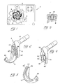
- Reference numeral 1 in Fig. 1 generally designates a barking machine which includes, besides a supporting frame or housing 2, a rotor 3 on which a number of tools 4 according to the invention are mounted.
- the embodiment illustrated comprises five tools, but this number may vary. In actual practice, many machines are equipped with six such tools.
- the rotor 3 is annular, and through the hollow space 5 thereof a log 6 can be fed lengthwise by means of a suitable number of rotating rolls 7, for example three rolls which preferably are in the form of jagged rolls pivotally mounted in journals 8. It is pointed out that the jagged rolls 7 are distinctly separate from the rotor 3 in a direction perpendicular to the plane of the drawing so that the rolls will not come into contact with the rotor. It is also pointed out that a corresponding set of feed rolls are mounted on the rear side of the housing 2, such that a log can be fed before a log end has entered into contact with the tools, or discharged after a log end has lost contact with the tools.
- the tool illustrated in Figs. 2-4 comprises the actual swinging arm 9 and a shaft 10 which is journaled in the rotor 3 and which at its end protruding from the rotor has a holder 11.
- the holder 11 preferably is formed in one piece with the shaft 10, but may also be designed as a separate part which subsequently is firmly connected with the shaft 10.
- the swinging arm 9 is curved and has at its free end remote from the holder 11 a seat 12 adapted to accommodate a detachable cutting tool (not shown) which incorporates the cutting edge performing the actual barking operation.
- a cutting tool is shown in Fig. 6 where it is designated 13.
- the cutting edge proper of the tool is designated 14.
- the swinging arm 9 is detachably connected with the holder 11 via a screw connection which, in the embodiment illustrated, comprises two screws 15, 15' which are in engagement with threaded holes 16, 16' in the holder 11 and extend through oblong holes 17, 17' in the arm 9.
- the holder 11 is formed with two elongated circularly curved grooves 18, 18' spaced apart by an intermediate ridge 19 in which the threaded holes 16, 16' are drilled. These grooves are adapted to receive two beads 21, 21' formed on the swinging arm 9 and spaced apart by an intermediate recess 20.
- the holes 17, 17' for the screws 15, 15' are also curved with a radius of curvature, the center of which coincides with that of the circular grooves 18, 18' and the beads 21, 21', respectively.
- the swinging arm 9, after detachment of the screws 15, 15' can be displaced relative to the holder 11 into an optionally selectable position between two end positions determined by the length of the holes 17, 17', whereupon the arm can be fixed in the desired position by tightening the screws 15, 15'.
- the distance between the center of the pivot shaft 10 and the center of gravity of the swinging arm 9 can be varied such that the center of gravity is maximally approached to the center of the shaft 10 in the position shown in Fig. 2 and can be removed from said center by displacement of the arm in a direction outwardly from the holder toward the opposite end position.
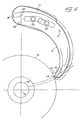
- Fig. 6 the tool is assumed to work a relatively thick log 6'.
- the arm 9 has been pushed into its inner end position relative to the holder 11, whereby a minimum distance is obtained between the center of gravity T of the swinging arm and a straight line between the rotor center C and the shaft center 10'.
- the cutting tool 13 operates at a practically ideal angle of attack between the cutting tool 13 and the log circumference. It should be noted that this angle of attack is a negative one, whereby the cutting tool will remove the bark layer by shearing rather than by cutting.
- the swinging arm is set to the position shown by dash-dot lines, in which the arm has been maximally removed or projected from the holder 11. In this position, the tool 13 can reach the log while maintaining an acceptable angle of attack and efficiently work the slender log.
Abstract
Description
- The present invention relates to a tool for rotation ring type barking machines, comprising a shaft rotatably mounted in a rotor of such a machine, a holder associated with said shaft and extending at an angle relative to the same, and a curved swinging arm which is adapted to carry a cutting edge at a first, free end thereof and which at the opposite end thereof is detachably connected to the holder by means of a screw connection. Such a tool is disclosed in Swedish Patent Specification 7412070.
- Barking machines of the above-mentioned type basically operate in such a manner that the individual log is fed lengthwise by means of rolls through the hollow space of an annular rotor on which a number of edge-carrying tools or swinging arms are hingedly mounted, at the same time as the rotor is caused to rotate, the tools and the cutting edges thereon being yieldably urged against the circumference of the log by means of suitable spring means enabling the cutting edges to follow any irregularities of the log surface. In these machines, logs of greatly varying thicknesses are worked, from slender stocks less than 100 mm in diameter to heavy saw timber with diameters in excess of 300 mm. In order to avoid that the swingable tools have to travel an unnecessarily long distance between the initial position which they assume during the periods between working of successive logs and the active position on the surface of a heavy log, the tools are adjustable in different initial positions by means of movable stops built into the rotor and limiting and determining the angle to which the spring means can swing the arms inwardly toward the center of the rotor, more particularly in such a manner that the tools in their initial positions are held swung-in with their cutting edges close to the center during working of an assortment of slender logs, whereas they are swung farther away from the center in the initial position for the working of thicker logs. In this manner, the tools need not climb an unnecessarily long distance over the log ends from the initial position to the active position during barking of heavy timber.
- During operation, when the rotor of the machine rotates at maximum speed to give maximum barking capacity, the force by which the spring means strive to urge the tool cutting edges against the log circumference is counteracted by the centrifugal force exered upon the tools by the rotation of the rotor. Naturally, the centrifugal force increases according as the rotor speed is increased. Furthermore, the pressure of the cutting edges upon the log is influenced by the positions of the centers of gravity of the tool arms relative to the associated pivot shafts, such that an increasing distance between the pivot shaft and the center of gravity exerts an increasing outwardly swinging torque on the swinging arms and thus a decreasing contact pressure of the cutting edges. In view hereof, if heavy logs are worked at high speeds, the contact pressure of the spring means may be counteracted to such an extent that the barking efficiency deteriorates.
- The present invention aims at obviating the above-mentioned disadvantage and at providing a barking tool which gives excellent barking results also on heavy logs at high rotor speeds. According to the principal feature of the invention, this is achieved in that the swinging arm is displaceably movable relative to the holder and fixable by means of said screw connection in different selectable positions relative thereto, in order to permit variation of the distance between the center of the pivot shaft and the center of gravity of the swinging arm.
- On the tool according to the invention, the swinging arm can thus be adjusted in a position maximally extended away from the holder, in which position the cutting edge lies close to the rotor center during working of slender logs, and adjusted in a position retracted against the shaft, in which position the cutting edge has been removed from the rotor center for barking thicker logs, the center of gravity of the swinging arm in the last instance being localised closer to the shaft than in the first instance, while minimising the torque exerted by the weight of the swinging arm and counteracting the contact pressure of said spring means.
- In the drawings
- Fig. 1 is a schematic front view of a rotation ring type barking machine;
- Fig. 2 is an enlarged perspective view of a tool according to the invention, included in the machine;
- Fig. 3 is a perspective view of a swinging arm included in the tool as shown in Fig. 2;
- Fig. 4 is a perspective view of a pivot shaft included in the tool, and the holder associated there with;
- Fig. 5 is a cross-sectional view of the tool in the assembled state; and
- Fig. 6 is an enlarged view showing the tool during working of a log.
-
Reference numeral 1 in Fig. 1 generally designates a barking machine which includes, besides a supporting frame orhousing 2, arotor 3 on which a number oftools 4 according to the invention are mounted. The embodiment illustrated comprises five tools, but this number may vary. In actual practice, many machines are equipped with six such tools. Therotor 3 is annular, and through thehollow space 5 thereof alog 6 can be fed lengthwise by means of a suitable number of rotating rolls 7, for example three rolls which preferably are in the form of jagged rolls pivotally mounted injournals 8. It is pointed out that the jagged rolls 7 are distinctly separate from therotor 3 in a direction perpendicular to the plane of the drawing so that the rolls will not come into contact with the rotor. It is also pointed out that a corresponding set of feed rolls are mounted on the rear side of thehousing 2, such that a log can be fed before a log end has entered into contact with the tools, or discharged after a log end has lost contact with the tools. - The tool illustrated in Figs. 2-4 comprises the actual swinging
arm 9 and ashaft 10 which is journaled in therotor 3 and which at its end protruding from the rotor has aholder 11. Theholder 11 preferably is formed in one piece with theshaft 10, but may also be designed as a separate part which subsequently is firmly connected with theshaft 10. The swingingarm 9 is curved and has at its free end remote from the holder 11 aseat 12 adapted to accommodate a detachable cutting tool (not shown) which incorporates the cutting edge performing the actual barking operation. Such a cutting tool is shown in Fig. 6 where it is designated 13. The cutting edge proper of the tool is designated 14. - As will appear from Figs. 2-5, the swinging
arm 9 is detachably connected with theholder 11 via a screw connection which, in the embodiment illustrated, comprises twoscrews 15, 15' which are in engagement with threadedholes 16, 16' in theholder 11 and extend throughoblong holes 17, 17' in thearm 9. Theholder 11 is formed with two elongated circularlycurved grooves 18, 18' spaced apart by anintermediate ridge 19 in which the threadedholes 16, 16' are drilled. These grooves are adapted to receive twobeads 21, 21' formed on the swingingarm 9 and spaced apart by anintermediate recess 20. Besides being oblong, theholes 17, 17' for thescrews 15, 15' are also curved with a radius of curvature, the center of which coincides with that of thecircular grooves 18, 18' and thebeads 21, 21', respectively. This means that the swingingarm 9, after detachment of thescrews 15, 15' can be displaced relative to theholder 11 into an optionally selectable position between two end positions determined by the length of theholes 17, 17', whereupon the arm can be fixed in the desired position by tightening thescrews 15, 15'. In this manner, the distance between the center of thepivot shaft 10 and the center of gravity of the swingingarm 9 can be varied such that the center of gravity is maximally approached to the center of theshaft 10 in the position shown in Fig. 2 and can be removed from said center by displacement of the arm in a direction outwardly from the holder toward the opposite end position. - In Fig. 6, the tool is assumed to work a relatively thick log 6'. In this case, the
arm 9 has been pushed into its inner end position relative to theholder 11, whereby a minimum distance is obtained between the center of gravity T of the swinging arm and a straight line between the rotor center C and the shaft center 10'. In this position, the cutting tool 13 operates at a practically ideal angle of attack between the cutting tool 13 and the log circumference. It should be noted that this angle of attack is a negative one, whereby the cutting tool will remove the bark layer by shearing rather than by cutting. - If the tool is to work a log 6'' having an extremely small diameter, the swinging arm is set to the position shown by dash-dot lines, in which the arm has been maximally removed or projected from the
holder 11. In this position, the tool 13 can reach the log while maintaining an acceptable angle of attack and efficiently work the slender log. - It will be appreciated that the invention is not restricted to the embodiment described above and illustrated in the drawings. For example, it is possible to form the bark-working cutting edge directly on the swinging arm proper, instead of on an exchangeable separate cutting tool. Furthermore, it is possible to use but one screw in the screw connection, although at least two screws are preferred in actual practice.
Claims (3)
- A tool for rotation ring type barking machines, comprising a shaft (10) rotatably mounted in a rotor (3) of such a machine, a holder (11) associated with said shaft and extending at an angle relative to the same, and a curved swinging arm (9) which is adapted to carry a cutting edge at a first, free end thereof and which at the opposite end thereof is detachably connected to the holder (11) by means of a screw connection (13, 13'), characterised in that said swinging arm (9) is displaceably movable relative to the holder and fixable by means of said screw connection (15, 15') in different selectable positions relative thereto, in order to permit variation of the distance between the center of the pivot shaft and the center of gravity of the swinging arm.
- A tool as claimed in claim 1, characterised in that an individual screw (15) of the screw connection (15,15') engages with a threaded hole (16,16') in the holder (11) and extends through an oblong hole (17) in the swinging arm (9).
- A tool as claimed in claim 2, characterised in that the oblong hole (17) has a circularly curved shape corresponding to the shape of a circularly curved guide in the form of at least one groove (18, 18') in said holder (11) and a bead (21, 21') formed on said swinging arm (9) and engaging with said groove.
Priority Applications (1)
| Application Number | Priority Date | Filing Date | Title |
|---|---|---|---|
| AT89850176T ATE92392T1 (en) | 1988-06-08 | 1989-05-30 | TOOL FOR DEBARKING MACHINES WITH ONE ROTATING RING. |
Applications Claiming Priority (2)
| Application Number | Priority Date | Filing Date | Title |
|---|---|---|---|
| SE8802140 | 1988-06-08 | ||
| SE8802140A SE463661B (en) | 1988-06-08 | 1988-06-08 | TOOLS FOR HALTING TYPE BARKING MACHINES |
Publications (3)
| Publication Number | Publication Date |
|---|---|
| EP0346310A2 EP0346310A2 (en) | 1989-12-13 |
| EP0346310A3 EP0346310A3 (en) | 1991-09-18 |
| EP0346310B1 true EP0346310B1 (en) | 1993-08-04 |
Family
ID=20372556
Family Applications (1)
| Application Number | Title | Priority Date | Filing Date |
|---|---|---|---|
| EP89850176A Expired - Lifetime EP0346310B1 (en) | 1988-06-08 | 1989-05-30 | Tool for rotation ring type barking machines |
Country Status (8)
| Country | Link |
|---|---|
| US (1) | US4865095A (en) |
| EP (1) | EP0346310B1 (en) |
| AT (1) | ATE92392T1 (en) |
| CA (1) | CA1318221C (en) |
| DE (1) | DE68908025T2 (en) |
| FI (1) | FI84705C (en) |
| NO (1) | NO171254C (en) |
| SE (1) | SE463661B (en) |
Families Citing this family (5)
| Publication number | Priority date | Publication date | Assignee | Title |
|---|---|---|---|---|
| USD419854S (en) | 1998-03-13 | 2000-02-01 | Forano International Inc. | Debarker arm |
| USD411097S (en) | 1998-08-05 | 1999-06-15 | Forano International Inc. | Holder for a debarker arm |
| US7350548B1 (en) * | 2006-10-16 | 2008-04-01 | Nicholson Manufacturing Ltd. | Swing arm assembly with replaceable insert for use with a debarker apparatus |
| US7806153B2 (en) * | 2008-01-15 | 2010-10-05 | Reimler James L | Log debarking blade |
| US7931055B2 (en) | 2009-02-10 | 2011-04-26 | Reimler James L | Log debarking tool and tool tip |
Family Cites Families (5)
| Publication number | Priority date | Publication date | Assignee | Title |
|---|---|---|---|---|
| US3709272A (en) * | 1971-07-08 | 1973-01-09 | R Bowers | Log debarking apparatus |
| SE415078B (en) * | 1974-09-25 | 1980-09-08 | Jonsson Karl Erik Arnold | DEBARKING TOOLS |
| US4438794A (en) * | 1979-07-23 | 1984-03-27 | Carpenter Aaron R | Bark tool and connection |
| US4280541A (en) * | 1980-01-10 | 1981-07-28 | Reimler Associates, Inc. | Debarking tool for log debarking machines |
| US4653559A (en) * | 1985-03-20 | 1987-03-31 | Nicholson Manufacturing Company | Forwardly-projecting debarking tool barker arm |
-
1988
- 1988-06-08 SE SE8802140A patent/SE463661B/en not_active IP Right Cessation
- 1988-10-26 CA CA000581380A patent/CA1318221C/en not_active Expired - Fee Related
- 1988-10-27 US US07/263,346 patent/US4865095A/en not_active Expired - Lifetime
-
1989
- 1989-05-30 DE DE89850176T patent/DE68908025T2/en not_active Expired - Fee Related
- 1989-05-30 EP EP89850176A patent/EP0346310B1/en not_active Expired - Lifetime
- 1989-05-30 AT AT89850176T patent/ATE92392T1/en active
- 1989-06-07 NO NO892341A patent/NO171254C/en not_active IP Right Cessation
- 1989-06-07 FI FI892801A patent/FI84705C/en not_active IP Right Cessation
Also Published As
| Publication number | Publication date |
|---|---|
| FI84705C (en) | 1992-01-10 |
| FI84705B (en) | 1991-09-30 |
| ATE92392T1 (en) | 1993-08-15 |
| NO892341D0 (en) | 1989-06-07 |
| EP0346310A2 (en) | 1989-12-13 |
| SE463661B (en) | 1991-01-07 |
| NO171254B (en) | 1992-11-09 |
| DE68908025T2 (en) | 1994-03-03 |
| NO171254C (en) | 1993-02-17 |
| CA1318221C (en) | 1993-05-25 |
| FI892801A0 (en) | 1989-06-07 |
| SE8802140L (en) | 1989-12-09 |
| US4865095A (en) | 1989-09-12 |
| DE68908025D1 (en) | 1993-09-09 |
| SE8802140D0 (en) | 1988-06-08 |
| NO892341L (en) | 1989-12-11 |
| FI892801A (en) | 1989-12-09 |
| EP0346310A3 (en) | 1991-09-18 |
Similar Documents
| Publication | Publication Date | Title |
|---|---|---|
| US5772368A (en) | Full-size router tilt base | |
| US4739682A (en) | Tube end finishing machine | |
| US4669923A (en) | Radius cutting edging tool with guide wheel | |
| US5528830A (en) | Rotary cutting tool for tubing, conduit and the like | |
| EP0147401A1 (en) | Implement sharpening device | |
| US8608414B2 (en) | Bi-directional quick change tool-less lever and wedge actuated collet chuck, system and/or method for using the same | |
| EP0346310B1 (en) | Tool for rotation ring type barking machines | |
| US4892448A (en) | Cutter and drive gear assembly for dressing welding electrode tips | |
| US6004082A (en) | Tenon cutter | |
| US4266584A (en) | Edger saw combining chipper with circular saw blade | |
| CN210139486U (en) | Bamboo section inner segment strickles device off | |
| US5472027A (en) | Log bark slitting machine | |
| SE454249B (en) | FASTING DEVICE AT HANDLING POWER MACHINES | |
| US4630660A (en) | Dowell making | |
| EP0346309B1 (en) | Tool for rotation ring type barking machines | |
| US5343911A (en) | Stave-cutting machine | |
| US4363342A (en) | Log milling apparatus | |
| US4467848A (en) | Machine for cutting down logs to a desired diameter | |
| US293224A (en) | Machine for lap-shaving hoops | |
| CN210139485U (en) | Bamboo section outer joint strickle device off | |
| CN211965958U (en) | Boring cutter for forming inner cavity of roller and lathe using boring cutter | |
| JPH05245803A (en) | Apparatus for working lumber rod | |
| AU2004200831A1 (en) | Chipping head | |
| CA1189766A (en) | Diametrical log sizer | |
| EP0591137A1 (en) | Rotary cutters |
Legal Events
| Date | Code | Title | Description |
|---|---|---|---|
| PUAI | Public reference made under article 153(3) epc to a published international application that has entered the european phase |
Free format text: ORIGINAL CODE: 0009012 |
|
| AK | Designated contracting states |
Kind code of ref document: A2 Designated state(s): AT DE FR |
|
| PUAL | Search report despatched |
Free format text: ORIGINAL CODE: 0009013 |
|
| AK | Designated contracting states |
Kind code of ref document: A3 Designated state(s): AT DE FR |
|
| 17P | Request for examination filed |
Effective date: 19920113 |
|
| 17Q | First examination report despatched |
Effective date: 19921113 |
|
| GRAA | (expected) grant |
Free format text: ORIGINAL CODE: 0009210 |
|
| AK | Designated contracting states |
Kind code of ref document: B1 Designated state(s): AT DE FR |
|
| PG25 | Lapsed in a contracting state [announced via postgrant information from national office to epo] |
Ref country code: FR Effective date: 19930804 |
|
| REF | Corresponds to: |
Ref document number: 92392 Country of ref document: AT Date of ref document: 19930815 Kind code of ref document: T |
|
| REF | Corresponds to: |
Ref document number: 68908025 Country of ref document: DE Date of ref document: 19930909 |
|
| EN | Fr: translation not filed | ||
| PLBE | No opposition filed within time limit |
Free format text: ORIGINAL CODE: 0009261 |
|
| STAA | Information on the status of an ep patent application or granted ep patent |
Free format text: STATUS: NO OPPOSITION FILED WITHIN TIME LIMIT |
|
| 26N | No opposition filed | ||
| PGFP | Annual fee paid to national office [announced via postgrant information from national office to epo] |
Ref country code: AT Payment date: 20000503 Year of fee payment: 12 |
|
| PGFP | Annual fee paid to national office [announced via postgrant information from national office to epo] |
Ref country code: DE Payment date: 20000713 Year of fee payment: 12 |
|
| PG25 | Lapsed in a contracting state [announced via postgrant information from national office to epo] |
Ref country code: AT Free format text: LAPSE BECAUSE OF NON-PAYMENT OF DUE FEES Effective date: 20010530 |
|
| PG25 | Lapsed in a contracting state [announced via postgrant information from national office to epo] |
Ref country code: DE Free format text: LAPSE BECAUSE OF NON-PAYMENT OF DUE FEES Effective date: 20020301 |