EP0346041B1 - Control system for air flotation dryer with a built-in afterburner - Google Patents
Control system for air flotation dryer with a built-in afterburner Download PDFInfo
- Publication number
- EP0346041B1 EP0346041B1 EP89305643A EP89305643A EP0346041B1 EP 0346041 B1 EP0346041 B1 EP 0346041B1 EP 89305643 A EP89305643 A EP 89305643A EP 89305643 A EP89305643 A EP 89305643A EP 0346041 B1 EP0346041 B1 EP 0346041B1
- Authority
- EP
- European Patent Office
- Prior art keywords
- control system
- air
- controlling
- including means
- temperature
- Prior art date
- Legal status (The legal status is an assumption and is not a legal conclusion. Google has not performed a legal analysis and makes no representation as to the accuracy of the status listed.)
- Expired - Lifetime
Links
Images


Classifications
-
- F—MECHANICAL ENGINEERING; LIGHTING; HEATING; WEAPONS; BLASTING
- F26—DRYING
- F26B—DRYING SOLID MATERIALS OR OBJECTS BY REMOVING LIQUID THEREFROM
- F26B13/00—Machines and apparatus for drying fabrics, fibres, yarns, or other materials in long lengths, with progressive movement
- F26B13/10—Arrangements for feeding, heating or supporting materials; Controlling movement, tension or position of materials
- F26B13/101—Supporting materials without tension, e.g. on or between foraminous belts
- F26B13/104—Supporting materials without tension, e.g. on or between foraminous belts supported by fluid jets only; Fluid blowing arrangements for flotation dryers, e.g. coanda nozzles
-
- F—MECHANICAL ENGINEERING; LIGHTING; HEATING; WEAPONS; BLASTING
- F26—DRYING
- F26B—DRYING SOLID MATERIALS OR OBJECTS BY REMOVING LIQUID THEREFROM
- F26B23/00—Heating arrangements
- F26B23/02—Heating arrangements using combustion heating
- F26B23/022—Heating arrangements using combustion heating incinerating volatiles in the dryer exhaust gases, the produced hot gases being wholly, partly or not recycled into the drying enclosure
Description
- The present invention relates to a control system for a web dryer such as for use in drying of a web in the printing industry, and more particularly, pertains to a control system for an air flotation dryer with a built-in afterburner which uses internal solvent-laden air as a combustion medium to generate high internal drying temperatures for use in drying a web.
- Prior art flotation dryers have been large and bulky in physical size, and have not operated at high efficiencies. Heat exchangers have been required in prior art systems to recapture heat in spent air. Burners would require excessive fuel in burning of the solvent laden air.
- Prior art web dryers were notorious in being operationally inefficient in web drying, consuming large amounts of physical floor space, and lacking in sophisticated computerized monitoring and control of the web dryer. Prior art web dryers attempted to reduce to a negligible amount the solvent concentration exhausted into the atmosphere through a variety of methods such as by using incinerators to combust the solvents in the dryer air, then attempting to recover the heat from the burned or combusted solvents by heat exchangers. Other methods include removing solvents from the air with the use of catalytic converters.
- Such flotation dryers are e.g. known by US-A-4,206,553.
- US-A-4282998 shows a device in which each run of the web is held in tension between two spaced contactless turning guides. The air from the turning guides cannot be said to dry the web, and where the web is being dried, by separately supplied heated air within
drying chamber 10, the web therefore cannot be said to float. - The present invention overcomes the disadvantages of the prior art by providing a control system which is applicable for use in an air flotation dryer with afterburners for drying of a web and which provides for control of electrical and electromechanical components on a real time basis.
- The general purpose of the present invention is to provide a control system for a compact and efficient air flotation dryer with a built-in afterburner where solvent-laden evaporate is combusted. This subsequently creates a heat source for use in drying a web, and also combusting a great majority of harmful noxious or pollutant vapors before such air is released into the atmosphere. Solvent-laden evaporate is propelled by an exhaust fan across a burner, which uses various premixes of a fuel medium and air, for combustion by the burner. The heat from the combusted solvents flow by forced air through an optional monolith catalyst, into a heat distribution chamber to be ducted to the interior of the enclosure, and to be propelled by a recirculation supply fan through additional ducting, and subsequently to air bars. The heated air may also alternatively be routed to the air bars through a sparger and a static mixer in series with the recirculating supply fan. Excess combusted air may be routed externally through an exhaust duct.
- The invention provides a control system according to
claim 1. - In one embodiment of the present invention, there is provided a control system for an insulated enclosure with four sides, a top and a bottom with access doors disposed along one side, and a system of interconnected fans, ducts, air bars, a burner, cladding and other elements contained therein. A variable speed exhaust fan is ported in the interior of the enclosure and connects to a combustion compartment by a steel duct. The combustion compartment includes a gas supply duct, a burner with air flow mixing plates and profile plates disposed horizontally about the burner and combustion chamber. The upper end of the combustion chamber connects to a transition chamber, which may include an optional monolith catalyst and a heat distribution chamber. The heat distribution chamber includes an exhaust duct with a plurality of ceramic alloy damper vanes therein, perpendicular to a side wall for accommodation of an external chimney flue. The heat distribution chamber also includes a hot air return duct attached thereto, including a plurality of ceramic alloy damper vanes venting to the dryer enclosure. In the alternative, a sparger and static mixer tube can connect the hot air return duct to a recirculating air supply fan. The circulating return air fan is connected by a circulating air plenum directly to a lower supply duct and through a vertical duct to an upper supply duct. The upper and lower supply ducts connect to horizontally oriented, vertically moveable supply headers which connect to a plurality of opposing air bar members. The air bar members secure between opposing upper and lower frame pairs. The control system provides for coordinated control of exhaust fan speed, damper positions and burner firing rate in real time processing by a microprocessor or programmable logic controller. A subroutine controls the functioning of the electrical and electromechanical components.
- One significant aspect and feature of the present invention is control by a computer of exhaust fan speed, damper positioning, and burner firing rate. The exhaust fan speed is controlled with respect to the plenum pressure. The burner firing rate is controlled with respect to the combustion chamber temperature. The supply air temperature is controlled by the position of the hot air return damper which regulates the hot combustion in the burner area.
- Another significant aspect and feature of the present invention are computer subroutines which provide for real time processing of data from the LFL monitor, the plenum pressure, and the combustion chamber pressure, as well as the monitoring and controlling of other system operational parameters.
- Another significant aspect and feature of the present invention is control of both air/web temperature demand and oxidation temperature demand with only one heat source.
- Another significant aspect and feature of the present invention is operation at relationships of O₂ and methane previously not attainable; therefore, obtaining improved fuel efficiency.
- Another significant aspect and feature of the present invention is closed loop control of a combination system (dryer/afterburner).
- Having thus described the embodiments of the present invention, it is the principal object hereof to provide a control system for an air flotation dryer with an integral built-in afterburner for the combustion of vaporous flammable solvents in laden air within the air flotation dryer.
- An object of the present invention is to provide real time control of the exhaust fan speed, burner firing rate, and the damper positions by a computer.
- Another object of the present invention is to provide a control system which is applicable for use with any air flotation dryer with a built-in afterburner.
- Other objects of the present invention include improved system efficiency by attaining an appropriate relationship of O₂ and methane. Control is provided of both air/web temperature demand and oxidation temperature with only one heat source. Closed loop control is also provided for a combination system of an air flotation dryer and an afterburner. While the air flotation dryer and afterburner are disclosed as being in the same housing, any of the components can be located external to the housing structure.
- Reference is made to the following detailed description in connection with the accompanying drawings, in which like reference numerals designate like parts throughout the figures thereof and wherein:
- FIG. 1 illustrates a perspective view in cutaway cross section of an air flotation dryer with a built-in afterburner;
- FIG. 2 illustrates a top view in cutaway cross section of an air flotation dryer with a built-in afterburner;
- FIG. 3 illustrates a perspective view of the circulating air plenum;
- FIG. 4 illustrates a rear view of an air flotation dryer with a built-in afterburner;
- FIG. 5 illustrates a side view of the combustion compartment;
- FIG. 6 illustrates an air flow schematic diagram for the air flotation dryer with a built-in afterburner;
- FIG. 7 illustrates an electromechanical computer control diagram of the air flotation dryer with a built-in afterburner with a computer connected to the components;
- FIG. 8 illustrates the legends for FIG. 6;
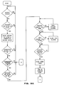
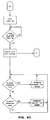
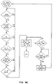
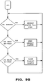
- FIG. 9A-9G illustrate a flow chart for the computer of FIG. 7.
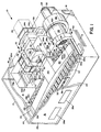
- FIG. 1 illustrates a perspective view in cutaway cross section of an air flotation dryer with a built-in afterburner, hereinafter referred to and designated the
dryer 10. A dryer enclosure 11 includesside members top 20 and abottom 22, each of which includes insulation cladding 24 between a plurality ofsteel cladding sheets 23a-23n and the inner surface of each of the members. The side members 12-18, the top 20 and the bottom 22 secure over and about a plurality offrame members 25a-25n. A plurality of access doors 26a-26n are disposed alongside member 12 for access to a plurality of opposing aligned upper air bars 28a-28n and lower air bars 30a-30n mounted in upper frame pairs 32-34 and lower frame pairs 36-38, respectively. A web passes between the pluralities of upper and lower air bars 28a-28n and 30a-30n, respectively, for drying of the passing web, and enters and exits the dryer enclosure 11 atslots chamber 33 secures over theentry slot 29. An upperair supply header 40 and a lowerair supply header 42 provides heated drying air to the respective upper and lower air bars 28a-28n and 30a-30n. The upper and lowerair supply headers enclosures - A
lower supply duct 46, illustrated in FIGS. 2 and 3, aligns below anupper supply duct 44, and provide pressurized heated drying air to the upper and lowerair supply headers air plenum 48 of FIG. 3 connects with avertical duct 49 and ahorizontal duct 47, between theupper supply duct 44 and thelower supply duct 46 and delivers recirculated air from a recirculatingair supply fan 50 powered by amotor 52 and adrive mechanism 54. Electrically drivendampers ducts makeup air damper 59 located onside member 16 opens to maintain a desired dryer negative pressure if the dryer negative pressure exceeds a preset maximum value. Thedryer afterburner 55 includes, among other members, a variablespeed exhaust fan 56, powered byexhaust fan motor 58 and having aninlet screen 60. Thefan 56 draws solvent-laden or otherwise flammable gaseous enclosure air through thefan inlet 57 and propels the air through ametal duct 62 to a ceramicinsulated combustion compartment 64. The air combusts in or near the flame of aburner 66 where the remaining solvent can be rapidly oxidized down stream of the flame of theburner 66. Agas supply duct 68 supplies gas to theburner 66. Theburner 66 is a raw gas type burner with partial premix of combustion air. The partial premix stabilizes the flame when the exhaust air stream becomes low in oxygen, below 16% oxygen, by way of example and for purposes of illustration only. The gas supply delivered through the gas supply duct can also include a full air and methane premix. Methane, air, and residual heavy weight hydrocarbons C₁₂ - C₂₃ from the dryer enclosure are combusted in theburner 66. A perforated air flow straightener plate positions about the lower portion of theburner 66 to distribute the output of the variable speed exhaust fan evenly across theburner 66. Aprofile plate 72 positions horizontally across the ceramicinsulated combustion compartment 64 and about theburner 66 to regulate or modify air flow differential between the area above and the area below the burner. Down stream combustion can be further augmented by an optional high spacevelocity monolith catalyst 74 as desired. Thecatalyst 74 secures in atransition chamber 76 between the ceramicinsulated combustion compartment 64 and aheat distribution chamber 78. The catalyst can be a bead or monolithic form or bead-monolithic form, each of which can include a precious metal, a base metal, a precious metal and a base metal combination, or any other form of catalyst as required either in a bead form, monolithic form, or a combination of bead form and monolithic form. A plurality ofexpansion joints 80a-80n as illustrated position between various members of the afterburner, such as between the output of the variablespeed exhaust fan 56 and the ceramicinsulated combustion compartment 64, between thecombustion compartment 64 and thetransition chamber 76, between thetransition chamber 76 and theheat distribution chamber 78, and in the mid-portion of theheat distribution chamber 78. - Heated air from the ceramic
insulated combustion compartment 64 is forced by the variablespeed exhaust fan 56 into theheat distribution chamber 78, and can be channeled into either two directions. First, heated air from theheat distribution chamber 78 can pass to the exterior of the dryer enclosure 11, through anexhaust duct 82 protruding perpendicular fromside member 16 and through servo controlled hot exhaust damper vanes 84a-84n contained in the flow path of theexhaust duct 82 and to atmosphere through aflue 85. Second, the other portion of the heated air can pass from theheat distribution chamber 78 into a hotair return duct 86, through servo controlled hot air return damper vanes 88a-88n, and into the interior of the dryer enclosure 11 through theend orifice 90 of the hotair return duct 86. Anoptional sparger assembly 92, including asparger ring 94, asparger housing 96, and aninlet screen 97, is illustrated between the hotair return duct 86 and the recirculatingfan inlet 100 of the recirculatingair supply fan 50. An optionalstatic mixer tube 98 is shown disposed between theoptional sparger assembly 92 and the recirculatingfan inlet 100. Without utilization of the sparger assembly, the heated air from the interior of the dryer enclosure 11 is drawn partially by the variablespeed exhaust fan 56 and partially by the recirculatingair supply fan 50. The recirculatingair supply fan 50 supplies heated pressurized air through the circulatingair plenum 48, thevertical duct 49, and upper andlower supply ducts - Mixing of dedicated air flow is accomplished by the use of the
optional sparger assembly 92. Of course, theend orifice 90 would then be located on theside wall 86a of the hotair return duct 86 and aligned with thesparger housing 96. Hot air from the hotair return duct 86 then flows through the hotair return duct 86, the servo controlled hot air return damper vanes 88a-88n, through theend orifice 90, through thesparger housing 96, through a plurality of holes 102a-102n in thesparger ring 94, into the recirculatingair supply fan 50, and through the appropriate supply ducts. This supplies heated pressurized air to the upper and lower air bars 28a-28n and 30a-30n. Approximately 75% of the system air flow passes through the recirculatingair supply fan 50 to the upper and lower air bars 28a-28n and 30a-30n. As previously described in detail, a portion of the heated air flow can be exhausted overboard through theexhaust duct 82 or through the hotair return duct 86 to maintain internal temperatures in a desired range. - FIG. 2 illustrates a top view in cutaway cross section of the
dryer 10 where all numerals correspond to those elements previously described. Shown in particular detail is thevertical duct 49 connected between the circulatingair plenum 48 and theupper supply duct 44. - FIG. 3 is a perspective view of the circulating
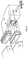
air plenum 48 illustrating vertical andhorizontal ducts dampers air plenum 48 and theducts ducts air plenum 48 can be referenced on FIG. 2 wherein the plenum is located partially beneath theheat distribution chamber 78 and to the left of the recirculatingair supply fan 50 and hotair return duct 86. - FIG. 4 illustrates a rear view of the
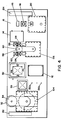
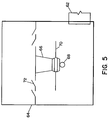
dryer 10 where all numerals correspond to those elements previously described.Motors plates side member 16. Other elements mounted on theside member 16 include the makeupair damper door 59, theexhaust duct 82, anaccess door 112, acatalyst access door 114, anultraviolet scanner 116, aburner sight port 118, aburner access door 120, hightemperature limit switches thermocouples air sample ports 130a-130n.Enclosures air supply headers - FIG. 5 illustrates a side view of the ceramic
insulated combustion compartment 64 where all numerals correspond to those elements previously described.Plate 70 is a perforated air straightened plate for channeling incoming air from themetal duct 62 vertically through or adjacent to theburner 66. Theprofile plates 72 are adjustable to control air passage rates through and by theburner 66, and to also control combustion rates in the ceramicinsulated combustion compartment 64. - FIGS. 1-5 illustrate the electromechanical mode of operation of the
dryer 10. A typical graphic arts dryer may have a "web" heat load of 500,000 net Btu/hr. This is the heat required to "dry" the ink on the paper web. Typically, the supply air temperature is about 350°F +/- 150°F, and the final web temperature is about 300°F +/- 100°F. In the present invention, spent, solvent-laden air is exhausted through a variablespeed exhaust fan 56, through ametal duct 62, and past aburner 66 where the exhaust stream is heated to about 1600°F (870°C). Most of the solvent in the exhaust stream is combusted in or near the burner flame, and the remaining solvent is oxidized rapidly downstream of the burner flame. Downstream combustion may be augmented by an optional high spacevelocity monolith catalyst 74 if desired. - The
burner 66 is a raw gas type burner with partial premix of combustion air. The partial premix stabilizes the flame when the exhaust air stream becomes low in oxygen such as below 16% oxygen. - One factor of operation is high temperature combustion of 600° to 2200°F (315° - 1180°C) with the
hot combustion compartment 64 being completely contained within the dryer enclosure 11. Due to high temperature of the exhaust through theheat distribution chamber 78, the exhaust rate is lowered by the hot exhaust damper vanes 84a-84n. The solvent concentration is controlled to 50% or less of lower flammability limit (LFL) indirectly by the variablespeed exhaust fan 56 which controls combustion compartment pressure. An air gap is left between the exterior of thecombustion compartment 64 and theinternal cladding sheets 23a-23n of the dryer walls, top, side, and bottom members 12-22 which minimizes the need for insulation in the combustion chamber. - The speed of the variable
speed exhaust fan 56 is controlled to maintain a constant combustion chamber pressure. After startup, the overall exhaust rate is reduced by closing the ceramic alloy hot exhaust damper vanes 84a-84n until an LFL of 50% is reached or until a preset minimum is reached or until a specific box negative pressure is reached. Solvent concentration is monitored with the lower flammable limit (LFL) monitor. The LFL monitor overrides the normal control of hot exhaust damper vanes 84a-84n to maintain the LFL of 50% or less. The firing rate of theburner 66 is controlled by the temperature set point in the ceramicinsulated combustion compartment 64. The supply air "web drying air" temperature is controlled by servo controlled hot air return damper vanes 88a-88n which allows hot combustion products to flow directly back to the recirculatingfan inlet 100. Anoptional sparger assembly 92 and/orstatic mixer tube 98 can be used to enhance the mixing of the hot return air from the hotair return duct 86 with the supply air. - FIG. 6 illustrates an air flow schematic diagram of the air flotation dryer with a built-in afterburner. The flow paths of the solvent laden air corresponds to the structure of FIGS. 1-5.
- The computer control of the built-in variable speed exhaust fan, dampers, makeup air, burner temperatures, and box pressures is utilized to maintain optimum combustion chamber temperature, supply air temperature, supply air flow, solvent concentration (LFL), and exhaust air rate. High clean-up efficiencies of 99% and higher can be achieved with the synergistic system.
- FIG. 8 illustrates the legends for FIG. 7. The instrument identification letters are set forth below in Table 1. While not specifically illustrated by lines in the figure, all instrumentation is wired to the computer to input operational parameters.
Table 1 Instrument Identification Letters AE Analysis Element AIC Analysis Indicating Controller AIT Analysis Indicating Transmitter AZ Analysis Final Control PI Pressure Indicator PIC Pressure Indicating Controller PIS Pressure Indicating Switch PT Pressure Transmitter PZ Pressure Final Control TE Temperature Element TIC Temperature Indicating Controller TZ Temperature Final Control - FIGS. 9A-9G illustrate flow charts for one subroutine for controlling the computer of FIG. 7. FIGS. 9A-9D pertain to initializing system operation and real time processing control during the running of the air flotation dryer with the built-in afterburner. FIGS. 9E-9F pertain to the LFL subroutines. FIG. 9G pertains to the make up air and the plenum temperature.
- During startup, the exhaust damper is open to a preset maximum, and after a startup cycle, the exhaust damper starts to close automatically in order to reduce the exhaust rate and increase the LFL. The exhaust damper continues to close until either the LFL reaches 50%, the damper setting reaches a preset minimum, or until the dryer box negative pressure reaches a preset minimum value.
- During purge, startup, blanket wash and idle cycles, the exhaust fan speed and damper positions are held at preset values.
- Based on the rapid warm-up time, there does not need to be any fuel consumption during idle time.
- If box negative pressure exceeds a preset maximum value, the makeup air damper opens to maintain a desired box negative pressure.
- The computer and the program controls the exhaust fan speed, the damper positions, and the burner firing rate.
- The computer monitors solvent concentration with an LFL monitor. The computer also controls exhaust fan speed with respect to plenum pressure, controls burner firing rate based on the combustion chamber temperature, and controls supply air temperature via position of the hot return damper which allows hot combustion products to return to dryer recirculation fan (supply air fan) inlet. The computer also controls LFL exhaust rate by the exhaust fan speed and controls plenum pressure via position of the exhaust damper.
- The control system provides the following operating criteria. The dryer supply air and combustion chamber temperatures reach operating set point within a period after a cold startup. The combustion chamber temperatures are between 1200 to 1900°F (645 - 1050°C). The dryer supply air temperature holds within +/-10°F of set point and combustion chamber temperature hold within +/-50°F of set point. The exhaust air flow rate is high enough to control dryer solvent concentration below 50% of LFL and prevent belching, and otherwise is at a minimum to reduce fuel consumption. The combustion chamber plenum pressure remains fairly constant to prevent erratic burner behavior. The oxygen level remains high enough to allow operation of an LFL monitor. The system is able to operate with only one burner, but may operate with additional secondary burners if desired. The VOC reduction must be 99% conversion or better. The system is able to operate without any heat exchanger, but may utilize a heat exchanger if desired. There is minimized fuel consumption during idle time.
- The control system provides for efficient hydrocarbon cleanup. The system maintains a predetermined web temperature while controlling and monitoring operating parameters. The speed of the exhaust fan is adjusted up or down to maintain a predetermined pressure in the combustion compartment or the heat distribution compartment. The hot air return damper is controlled by the temperature of the web or the supply air as predetermined and chosen. The burner firing rate is controlled to maintain a predetermined temperature in the combustion chamber. The makeup damper opens if the box negative pressure reaches a preset maximum. The system also monitors door interlocks and the burner flame. The exhaust damper is closed until the LFL is 50% or a predetermined maximum. If the exhaust damper reaches a predetermined minimum before the LFL is 50%, then the exhaust damper stops closing; or, if the box negative pressure reaches a predetermined minimum, then the exhaust damper stops closing. The system, in response to an LFL of greater than 50%, opens the exhaust damper and if the LFL rises above 60%, the system is shut down. The algorithm stored in the computer provides real time processing to control parameters in response to sensed parameters.
- Various modifications can be made to the present invention as follows: Components can be located external to the housing and ducted accordingly for connection thereto. One example would be the exhaust fan. There may be only one damper vane or several vanes as shown. Ceramic may or may not be used for insulation of ducts and vanes.
Claims (20)
- A control system for an air flotation dryer (10) with built-in afterburner including an enclosure (11) internally supporting opposing air bars (28a, 30a) said air bars being adapted to support, by flotation, a web to be dried therebetween, said control system comprising:(a) an air supply means (56) for supplying air to said air bars;(b) means for monitoring plenum pressure in a combustion chamber (64);(c) means in an afterburner (55) for monitoring temperature in the combustion chamber;(d) computer means connected to said combustion chamber temperature monitoring means and said plenum pressure monitoring means; and(e) an algorithm in said computer means for controlling the temperature in said combustion chamber by controlling the speed of an exhaust fan for said combustion chamber, and by controlling the position of an exhaust damper (84a - 84n) on said enclosure.
- A control system according to claim 1 wherein said computer means is a programmable logic controller.
- A control system according to claim 1 or 2, including means for controlling air pressure in said enclosure in response to a pressure sensor.
- A control system according to any one of claims 1 to 3, including means for controlling a hot air return damper (88a - 88n) in response to temperature of said web or supply air temperature.
- A control system according to any one of claims 1 to 4, including means for maintaining web temperature.
- A control system according to any one of claims 1 to 5, including means for maintaining hydrocarbons in a predetermined range.
- A control system according to any one of claims 1 to 6, including means for monitoring safety interlocks.
- A control system according to any one of claims 1 to 7, including means for monitoring the burner flame.
- A control system according to any one of claims 1 to 8, including means for controlling burner firing rate to maintain a predetermined temperature in said combustion chamber.
- A control system according to any one of claims 1 to 9, including means for opening and controlling a make-up air damper (5a) if said enclosure reaches a predetermined negative pressure.
- A control system according to any one of claims 1 to 10, including means for controlling the speed of said exhaust fan to maintain a predetermined pressure in said combustion chamber.
- A control system according to any one of claims 1 to 11, including means for controlling speed of said exhaust fan to maintain a predetermined pressure in a heat distribution compartment.
- A control system according to any one of claims 1 to 12, including means for controlling said exhaust damper position in response to LFL concentration.
- A control system according to any one of claims 1 to 13, including means opening said exhaust damper in response to a high LFL concentration.
- A control system according to any one of claims 1 to 14, including means for shutting down in response to sensing a high LFL.
- A control system according to any one of claims 1 to 15, including means for controlling exhaust damper position in response to sensing a predetermined pressure in said dryer enclosure.
- A control system according to any one of claims 1 to 16, including means for controlling oxygen concentration in response to sensing methane concentration.
- A control system according to any one of claims 1 to 17, wherein said computer means is a microprocessor.
- A control system for an air flotation dryer according to any one of claims 1 to 18, wherein said algorithm is effective for controlling plenum pressure, controlling burner firing rate of said afterburner, and for controlling position of a hot air return damper (88a ... 88n) connected to said plenum.
- A control system according to any one of claims 1 to 18, wherein said computer means are connected to monitoring means for said solvent concentration.
Applications Claiming Priority (2)
| Application Number | Priority Date | Filing Date | Title |
|---|---|---|---|
| US203129 | 1988-06-07 | ||
| US07/203,129 US4942676A (en) | 1988-06-07 | 1988-06-07 | Control system for air flotation dryer with a built-in afterburner |
Publications (3)
| Publication Number | Publication Date |
|---|---|
| EP0346041A2 EP0346041A2 (en) | 1989-12-13 |
| EP0346041A3 EP0346041A3 (en) | 1991-05-29 |
| EP0346041B1 true EP0346041B1 (en) | 1994-02-02 |
Family
ID=22752634
Family Applications (1)
| Application Number | Title | Priority Date | Filing Date |
|---|---|---|---|
| EP89305643A Expired - Lifetime EP0346041B1 (en) | 1988-06-07 | 1989-06-05 | Control system for air flotation dryer with a built-in afterburner |
Country Status (5)
| Country | Link |
|---|---|
| US (1) | US4942676A (en) |
| EP (1) | EP0346041B1 (en) |
| JP (1) | JP2937200B2 (en) |
| CA (1) | CA1337361C (en) |
| DE (1) | DE68912829T2 (en) |
Families Citing this family (23)
| Publication number | Priority date | Publication date | Assignee | Title |
|---|---|---|---|---|
| DE3939190A1 (en) * | 1989-01-25 | 1990-08-09 | Baldwin Gegenheimer Gmbh | CONTINUOUS DRYER OF ROLLER ROTATION PRINTING MACHINES AND OPERATION OF SUCH A CONTINUOUS DRYER FOR CONTINUOUS PRESSURE AND CYLINDER WASHING WITH A RUNNING TRAIN |
| NL8902754A (en) * | 1989-11-07 | 1991-06-03 | Stork Contiweb | CONTROL OF THE CONCENTRATION OF SOLVENTS IN A DRIER. |
| US5177877A (en) * | 1989-12-28 | 1993-01-12 | Am International, Inc. | Dryer-fuser apparatus and method for high speed electrophotographic printing device |
| US5182870A (en) * | 1990-08-30 | 1993-02-02 | The Dow Chemical Company | System and method for recovering volatile organic gases emitted from a polyethylene resin product |
| DE69113959T2 (en) * | 1990-12-03 | 1996-04-25 | Mitsubishi Heavy Ind Ltd | Drying device and its control device for rotary printing press. |
| US5134788A (en) * | 1990-12-20 | 1992-08-04 | Advance Systems Inc. | Dryer apparatus for floating a running web and having an exhaust flow rate control system |
| US5136790A (en) * | 1991-03-07 | 1992-08-11 | Thermo Electron-Web Systems, Inc. | Method and apparatus for drying coated webs |
| DE59107436D1 (en) * | 1991-09-21 | 1996-03-28 | Solipat Ag | Method and device for shrinking textile fabrics |
| DE4207071A1 (en) * | 1992-03-06 | 1993-09-16 | Heidelberger Druckmasch Ag | CONTROL SYSTEM FOR ROLLER ROTATION PRINTING MACHINES |
| US5189811A (en) * | 1992-03-18 | 1993-03-02 | Merck & Co., Inc. | Method and assemblage for controlling and managing lower explosion levels |
| US5524363A (en) * | 1995-01-04 | 1996-06-11 | W. R. Grace & Co.-Conn. | In-line processing of a heated and reacting continuous sheet of material |
| US5555635A (en) * | 1995-01-18 | 1996-09-17 | W. R. Grace & Co.-Conn. | Control and arrangement of a continuous process for an industrial dryer |
| DE19701084A1 (en) * | 1997-01-15 | 1998-07-16 | Hans Georg Platsch | Drying system for printed flat sheets |
| DE19713529A1 (en) * | 1997-04-01 | 1998-10-08 | Heidelberger Druckmasch Ag | Dryer for a material web with exhaust gas circulation |
| US6302188B1 (en) | 1998-04-28 | 2001-10-16 | Megtec Systems, Inc. | Multi-layer heat exchange bed containing structured media and randomly packed media |
| DE10318761A1 (en) * | 2003-04-25 | 2004-11-25 | A. Monforts Textilmaschinen Gmbh & Co.Kg | Method for checking a machine operated with air circulation |
| BRPI0707242A2 (en) * | 2006-01-25 | 2011-04-26 | Bekaert Sa Nv | flame dryer |
| US7993599B2 (en) * | 2006-03-03 | 2011-08-09 | Zeropoint Clean Tech, Inc. | Method for enhancing catalyst selectivity |
| JP4668093B2 (en) * | 2006-03-08 | 2011-04-13 | 富士機械工業株式会社 | Printer control device |
| DE102016001893A1 (en) * | 2016-02-17 | 2017-08-17 | Eisenmann Se | Burner unit and device for tempering objects |
| JP6280194B1 (en) * | 2016-12-12 | 2018-02-14 | 中外炉工業株式会社 | Paint drying apparatus and paint drying method |
| JP6933089B2 (en) * | 2017-10-27 | 2021-09-08 | 井関農機株式会社 | Crop dryer |
| KR102168656B1 (en) * | 2020-05-22 | 2020-10-21 | 케이씨코트렐 주식회사 | The tenter apparatus |
Family Cites Families (21)
| Publication number | Priority date | Publication date | Assignee | Title |
|---|---|---|---|---|
| US2750680A (en) * | 1952-08-02 | 1956-06-19 | Oxy Catalyst Inc | Method for treating materials |
| US2706344A (en) * | 1953-03-11 | 1955-04-19 | Southern Wood Preserving Co | Method of controlled air seasoning of wood |
| US2743529A (en) * | 1954-07-06 | 1956-05-01 | Oxy Catalyst Inc | Drying oven and operation thereof |
| US2795054A (en) * | 1954-10-07 | 1957-06-11 | Oxy Catalyst Inc | Method and apparatus for heat recovery from drying oven effluents |
| US3561928A (en) * | 1966-10-31 | 1971-02-09 | Electro Isolier Ind Wahn | Gas purifying apparatus |
| CA951190A (en) * | 1970-10-30 | 1974-07-16 | Dwight M. Wilkinson | Method and apparatus for drying solvents |
| JPS5615012Y2 (en) * | 1971-08-06 | 1981-04-08 | ||
| US3737280A (en) * | 1972-04-14 | 1973-06-05 | Hunter Eng Co | Emission-controlled paint line heat source |
| US3800429A (en) * | 1972-10-10 | 1974-04-02 | Dryer A Co | Particulate arresting means for cyclonic separator |
| JPS553607B2 (en) * | 1973-01-05 | 1980-01-25 | ||
| US3882612A (en) * | 1973-07-27 | 1975-05-13 | Moore Dry Kiln Co | Method and apparatus for limiting the concentration of combustible volatiles in dryer emissions |
| GB1429972A (en) * | 1973-08-24 | 1976-03-31 | Duur Kg Otto | Process of and apparatus for heating circulating air in drying quipment |
| US3909953A (en) * | 1974-02-28 | 1975-10-07 | Midland Ross Corp | Paint drying method and apparatus |
| US4116620A (en) * | 1977-05-23 | 1978-09-26 | Tec Systems, Inc. | Web drying apparatus having means for heating recirculated air |
| GB1583199A (en) * | 1977-12-01 | 1981-01-21 | Whiteley Ltd E Gordon | Cloth drying apparatus |
| US4205553A (en) * | 1979-02-21 | 1980-06-03 | The United States of America as represented by the Secretary of the Department of Transporation | Automated gain control in rail flaw detection |
| US4282998A (en) * | 1980-05-09 | 1981-08-11 | W. R. Grace & Co. | Maintenance of constant web clearance at contactless turning guide |
| US4575952A (en) * | 1981-09-18 | 1986-03-18 | M.E.G., S.A. | Hot air dryer structure |
| JPS58124113A (en) * | 1982-01-19 | 1983-07-23 | Chugai Ro Kogyo Kaisha Ltd | Atmosphere control for oven |
| JPS58175662A (en) * | 1982-04-09 | 1983-10-14 | Toshiba Mach Co Ltd | Drying furnace with deodorizer for printing press |
| US4591517A (en) * | 1984-06-08 | 1986-05-27 | Overly, Inc. | Web dryer with variable ventilation rate |
-
1988
- 1988-06-07 US US07/203,129 patent/US4942676A/en not_active Expired - Lifetime
-
1989
- 1989-06-05 DE DE68912829T patent/DE68912829T2/en not_active Expired - Lifetime
- 1989-06-05 EP EP89305643A patent/EP0346041B1/en not_active Expired - Lifetime
- 1989-06-06 CA CA000601908A patent/CA1337361C/en not_active Expired - Lifetime
- 1989-06-07 JP JP1145050A patent/JP2937200B2/en not_active Expired - Fee Related
Also Published As
| Publication number | Publication date |
|---|---|
| JP2937200B2 (en) | 1999-08-23 |
| DE68912829D1 (en) | 1994-03-17 |
| EP0346041A3 (en) | 1991-05-29 |
| US4942676A (en) | 1990-07-24 |
| CA1337361C (en) | 1995-10-17 |
| EP0346041A2 (en) | 1989-12-13 |
| DE68912829T2 (en) | 1994-09-08 |
| JPH0239938A (en) | 1990-02-08 |
Similar Documents
| Publication | Publication Date | Title |
|---|---|---|
| EP0346041B1 (en) | Control system for air flotation dryer with a built-in afterburner | |
| US5207008A (en) | Air flotation dryer with built-in afterburner | |
| EP0346042B1 (en) | Air flotation dryer with built-in afterburner | |
| CA2329795C (en) | Web dryer with fully integrated regenerative heat source | |
| EP1230517B1 (en) | Burner air/fuel ratio regulation method and apparatus | |
| US4501072A (en) | Dryer and printed material and the like | |
| AU2002219933B2 (en) | Web dryer with fully integrated regenerative heat source and control thereof | |
| JP2855632B2 (en) | Dryer for web material | |
| US4460331A (en) | Fume incineration for paint drying oven | |
| CA1307424C (en) | Compact combustion apparatus | |
| US6431859B1 (en) | Combustion gas and air recovery apparatus | |
| CA1052994A (en) | Convection oven and method of drying solvents | |
| JPH02282688A (en) | Device and method for generating radiant energy | |
| JP2531794B2 (en) | Dryer | |
| CA1057049A (en) | Radiant heating apparatus for curing coated strip material | |
| CA1057048A (en) | Method of curing strip coating | |
| JPH035836Y2 (en) | ||
| JPH0156184B2 (en) | ||
| CZ8500U1 (en) | Device for combustion and recirculation of air |
Legal Events
| Date | Code | Title | Description |
|---|---|---|---|
| PUAI | Public reference made under article 153(3) epc to a published international application that has entered the european phase |
Free format text: ORIGINAL CODE: 0009012 |
|
| AK | Designated contracting states |
Kind code of ref document: A2 Designated state(s): DE FR GB IT |
|
| PUAL | Search report despatched |
Free format text: ORIGINAL CODE: 0009013 |
|
| AK | Designated contracting states |
Kind code of ref document: A3 Designated state(s): DE FR GB IT |
|
| 17P | Request for examination filed |
Effective date: 19910729 |
|
| 17Q | First examination report despatched |
Effective date: 19920124 |
|
| GRAA | (expected) grant |
Free format text: ORIGINAL CODE: 0009210 |
|
| AK | Designated contracting states |
Kind code of ref document: B1 Designated state(s): DE FR GB IT |
|
| REF | Corresponds to: |
Ref document number: 68912829 Country of ref document: DE Date of ref document: 19940317 |
|
| ITF | It: translation for a ep patent filed |
Owner name: MODIANO & ASSOCIATI S.R.L. |
|
| ET | Fr: translation filed | ||
| PLBE | No opposition filed within time limit |
Free format text: ORIGINAL CODE: 0009261 |
|
| STAA | Information on the status of an ep patent application or granted ep patent |
Free format text: STATUS: NO OPPOSITION FILED WITHIN TIME LIMIT |
|
| 26N | No opposition filed | ||
| REG | Reference to a national code |
Ref country code: FR Ref legal event code: TP |
|
| REG | Reference to a national code |
Ref country code: GB Ref legal event code: 732E |
|
| REG | Reference to a national code |
Ref country code: GB Ref legal event code: IF02 |
|
| PG25 | Lapsed in a contracting state [announced via postgrant information from national office to epo] |
Ref country code: IT Free format text: LAPSE BECAUSE OF NON-PAYMENT OF DUE FEES;WARNING: LAPSES OF ITALIAN PATENTS WITH EFFECTIVE DATE BEFORE 2007 MAY HAVE OCCURRED AT ANY TIME BEFORE 2007. THE CORRECT EFFECTIVE DATE MAY BE DIFFERENT FROM THE ONE RECORDED. Effective date: 20050605 |
|
| PGFP | Annual fee paid to national office [announced via postgrant information from national office to epo] |
Ref country code: FR Payment date: 20070608 Year of fee payment: 19 |
|
| PGFP | Annual fee paid to national office [announced via postgrant information from national office to epo] |
Ref country code: DE Payment date: 20080612 Year of fee payment: 20 |
|
| PGFP | Annual fee paid to national office [announced via postgrant information from national office to epo] |
Ref country code: GB Payment date: 20080611 Year of fee payment: 20 |
|
| REG | Reference to a national code |
Ref country code: FR Ref legal event code: ST Effective date: 20090228 |
|
| REG | Reference to a national code |
Ref country code: GB Ref legal event code: PE20 Expiry date: 20090604 |
|
| PG25 | Lapsed in a contracting state [announced via postgrant information from national office to epo] |
Ref country code: FR Free format text: LAPSE BECAUSE OF NON-PAYMENT OF DUE FEES Effective date: 20080630 |
|
| PG25 | Lapsed in a contracting state [announced via postgrant information from national office to epo] |
Ref country code: GB Free format text: LAPSE BECAUSE OF EXPIRATION OF PROTECTION Effective date: 20090604 |