EP0346004B1 - Stoffaufheizvorgang - Google Patents
Stoffaufheizvorgang Download PDFInfo
- Publication number
- EP0346004B1 EP0346004B1 EP89305528A EP89305528A EP0346004B1 EP 0346004 B1 EP0346004 B1 EP 0346004B1 EP 89305528 A EP89305528 A EP 89305528A EP 89305528 A EP89305528 A EP 89305528A EP 0346004 B1 EP0346004 B1 EP 0346004B1
- Authority
- EP
- European Patent Office
- Prior art keywords
- annular
- matter
- zone
- mixture
- heated
- Prior art date
- Legal status (The legal status is an assumption and is not a legal conclusion. Google has not performed a legal analysis and makes no representation as to the accuracy of the status listed.)
- Expired - Lifetime
Links
- 238000010438 heat treatment Methods 0.000 title claims abstract description 37
- 239000012530 fluid Substances 0.000 claims abstract description 43
- 239000008246 gaseous mixture Substances 0.000 claims abstract description 32
- 238000000034 method Methods 0.000 claims abstract description 24
- 230000002269 spontaneous effect Effects 0.000 claims abstract description 7
- 239000000446 fuel Substances 0.000 claims description 38
- 238000002485 combustion reaction Methods 0.000 claims description 28
- 239000000203 mixture Substances 0.000 claims description 27
- 238000006243 chemical reaction Methods 0.000 claims description 14
- VNWKTOKETHGBQD-UHFFFAOYSA-N methane Chemical compound C VNWKTOKETHGBQD-UHFFFAOYSA-N 0.000 claims description 12
- 239000003345 natural gas Substances 0.000 claims description 7
- 239000011236 particulate material Substances 0.000 claims description 6
- 238000011144 upstream manufacturing Methods 0.000 claims description 5
- 239000007789 gas Substances 0.000 description 8
- 239000013618 particulate matter Substances 0.000 description 7
- 239000003054 catalyst Substances 0.000 description 3
- ATUOYWHBWRKTHZ-UHFFFAOYSA-N Propane Chemical compound CCC ATUOYWHBWRKTHZ-UHFFFAOYSA-N 0.000 description 2
- 230000002411 adverse Effects 0.000 description 2
- QVGXLLKOCUKJST-UHFFFAOYSA-N atomic oxygen Chemical compound [O] QVGXLLKOCUKJST-UHFFFAOYSA-N 0.000 description 2
- 238000010494 dissociation reaction Methods 0.000 description 2
- 230000005593 dissociations Effects 0.000 description 2
- 230000000694 effects Effects 0.000 description 2
- 239000001301 oxygen Substances 0.000 description 2
- 229910052760 oxygen Inorganic materials 0.000 description 2
- 239000007787 solid Substances 0.000 description 2
- OKTJSMMVPCPJKN-UHFFFAOYSA-N Carbon Chemical compound [C] OKTJSMMVPCPJKN-UHFFFAOYSA-N 0.000 description 1
- 229910052799 carbon Inorganic materials 0.000 description 1
- 239000004927 clay Substances 0.000 description 1
- 238000001816 cooling Methods 0.000 description 1
- 230000005484 gravity Effects 0.000 description 1
- 239000011874 heated mixture Substances 0.000 description 1
- 239000007788 liquid Substances 0.000 description 1
- 239000000463 material Substances 0.000 description 1
- 239000010451 perlite Substances 0.000 description 1
- 235000019362 perlite Nutrition 0.000 description 1
- 239000000843 powder Substances 0.000 description 1
- 239000001294 propane Substances 0.000 description 1
- 230000000630 rising effect Effects 0.000 description 1
- 239000010454 slate Substances 0.000 description 1
Images



Classifications
-
- F—MECHANICAL ENGINEERING; LIGHTING; HEATING; WEAPONS; BLASTING
- F27—FURNACES; KILNS; OVENS; RETORTS
- F27B—FURNACES, KILNS, OVENS OR RETORTS IN GENERAL; OPEN SINTERING OR LIKE APPARATUS
- F27B15/00—Fluidised-bed furnaces; Other furnaces using or treating finely-divided materials in dispersion
- F27B15/02—Details, accessories or equipment specially adapted for furnaces of these types
- F27B15/14—Arrangements of heating devices
-
- F—MECHANICAL ENGINEERING; LIGHTING; HEATING; WEAPONS; BLASTING
- F23—COMBUSTION APPARATUS; COMBUSTION PROCESSES
- F23C—METHODS OR APPARATUS FOR COMBUSTION USING FLUID FUEL OR SOLID FUEL SUSPENDED IN A CARRIER GAS OR AIR
- F23C10/00—Fluidised bed combustion apparatus
- F23C10/18—Details; Accessories
-
- F—MECHANICAL ENGINEERING; LIGHTING; HEATING; WEAPONS; BLASTING
- F23—COMBUSTION APPARATUS; COMBUSTION PROCESSES
- F23C—METHODS OR APPARATUS FOR COMBUSTION USING FLUID FUEL OR SOLID FUEL SUSPENDED IN A CARRIER GAS OR AIR
- F23C2900/00—Special features of, or arrangements for combustion apparatus using fluid fuels or solid fuels suspended in air; Combustion processes therefor
- F23C2900/99006—Arrangements for starting combustion
Definitions
- This invention relates to heating matter and is particularly, but not exclusively, applicable to methods of heating matter using apparatus as disclosed in specification EP-A-0068853 and copending British Specifications Nos. 2202618A, 2203670A, 2205049A and 2211597A, and in which matter is moved in a band continuously along an annular path in an annular zone by directing fluid flow into the zone over the annular extent thereof with both circumferential and vertical flow components. It will be understood that by utilising heated fluid for the fluid flow over at least a portion of the annular extent of the zone, there will be a heat transfer between the heated fluid and matter as the heated fluid passes through the band thereby heating the matter.
- a gaseous mixture which is reactable to produce heat may be used to provide a heated fluid flow
- the gaseous mixture may be a combustible gaseous mixture, typically comprising an air-gaseous fuel mixture.
- EP-A-0068853 discloses a method of heating matter comprising supplying said matter to a heating zone to be heated therein and providing in said heating zone a gaseous mixture which is reactable to produce heat and igniting said gaseous mixture within the extent of said matter to thereby provide a heated fluid flow in the heating zone.
- the reaction which produces the heated fluid flow should occur in the zone and must be rapid to ensure that the reaction is substantially completed within the extent of the band, which for example is typically 50mm deep.
- GB-A-2074889 discloses a method of heat treatment of foodstuffs in which a stream of oxygen-containing gas and fuel is passed over one or more catalysts to raise the temperature of the gas stream and the resulting hot gas stream is contacted with a foodstuff.
- a preheated gaseous mixture (the fuel and oxygen-containing gas) is provided in a heating zone where it reacts in contact with a catalyst bed to produce a heated fluid flow.
- Matter to be heated (a cool airstream for cooling the heated fluid flow or the foodstuff) is supplied to the heating zone downstream of the catalyst in which the heat producing reaction takes place.
- the present invention provides a method of heating matter comprising supplying said matter to a heating zone to be heated therein and providing in said heating zone a gaseous mixture which is reactable to produce heat and igniting said gaseous mixture within the extent of said matter to thereby provide a heated fluid flow in the heating zone, characterised in that said gaseous mixture is provided in said heating zone at a temperature above that at which spontaneous ignition thereof occurs such that said gaseous mixture reacts, with no flame front being present during the reaction, within the extent of said matter.
- the gaseous mixture comprises a combustible gaseous mixture and said heat producing reaction, with no flame front present, occurring in said heating zone is a combustion reaction.
- the combustible gaseous mixture comprises an air-gaseous fuel mixture.
- the invention is applicable to other methods of heating matter, it is especially applicable to the above-described method, in which case the matter to be heated is moved in a band continuously along an annular path in an annular zone by directing fluid flow into said zone over the annular extent thereof with both circumferential and vertical flow components, said fluid flow comprising said gaseous mixture over at least a portion of the annular extent of said zone, and the reaction thereof being substantially completed within the extent of said band.
- the fluid flow may comprise said gaseous mixture over the annular extent of said zone.
- the matter may comprise particulate material which forms a resident bed moving in said band along said annular path.
- the gaseous mixture may be directed into a first annular region of said annular zone, which region is contiguous with and disposed inwardly of a second annular region of said annular zone such that said reaction occurs substantially in said first annular region, and said matter is circulated between said regions whilst moving in said band.
- the gaseous mixture comprises an air-gaseous fuel mixture and the fluid flow is directed into said annular zone through an annular inlet comprising an annular array of fixed inclined vanes arranged in overlapping relationship, said gaseous fuel being mixed with heated air immediately upstream of respective passages defined between said vanes and combustion occurring downstream of said vanes.
- the air-gaseous fuel mixture is confined substantially to the region above the vanes by directing respective flows through said annular inlet at the radially inner and outer edges thereof with radially outwardly and radially inwardly flow components respectively.
- the gaseous fuel may comprise natural gas, and in an embodiment of the invention an air-natural gas mixture is supplied at a temperature greater than 700°C.
- the temperature of this mixture is obtained by mixing the natural gas with heated air at a temperature of less than about 1000°C, for example between 850 and 900°C.
- the illustrated apparatus comprises a chamber 10 having a circumferential wall 12 which is disposed radially outwardly of an annular inlet 14.
- the wall 12 slopes towards the annular inlet, and as shown comprises a cylindrical portion 16 extending upwardly from a sloping portion 18.
- the sloping portion 18 extends downwardly to the outer edge of the annular fluid inlet.
- first annular region disposed above the annular inlet and designated 22 in Figure 2 and a second annular region 24 contiguous with the first annular region and disposed between that region and the circumferential wall 12.
- the second region is disposed above the sloping portion 18 of the wall in the embodiment.
- the apparatus also includes means for directing fluid through the annular inlet 14 with vertical and circumferential flow components.
- the direction of the fluid flow through the inlet is indicated in Figure 2 by arrows 26 and 28.
- the flow of fluid through the inlet is such that it will move matter in the chamber 10 in a band continuously along an annular path in the regions 22, 24. This matter is moved vertically and circumferentially whilst in the first region 22 by the flow of fluid therein, is moved out of this flow of fluid in the first region into the second region by circumferential force and is directed back into the first region by the slope 18.
- the movement of the matter into and out of the flow of fluid is indicated by arrows 30 in Figure 2.
- the chamber 10 includes a second circumferential wall 34 extending upwardly and disposed radially inwardly of the annular fluid inlet 14.
- This circumferential wall 34 has a slope towards the annular fluid inlet such that matter introduced centrally into the chamber as indicated by arrows 36 will be directed into the first annular region 22 above the annular fluid inlet 14. Whilst the whole of the second circumferential wall is provided with such a slope in the embodiment and this slope extends to the radially inner edge 38 of the annular fluid inlet 14, it is to be understood that only a portion of the circumferential wall 34 need be provided with such a slope and that slope need not extend to the edge 38.
- the means for directing fluid through the annular inlet 14 with vertical and circumferential flow components in the illustrated apparatus comprises an annular array of fixed inclined vanes 40 arranged in overlapping relationship, and defining therebetween respective flow passages 42 which extend vertically and circumferentially.
- a portion of the annular array of vanes is schematically illustrated in Figure 3, however it is to be understood that the array extends completely around the annular inlet 14.
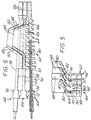
- Each vane 40 is part of a respective blade 44 which is best shown in Figure 7. Adjacent blades 44 nest together as illustrated in Figures 5 and 6 so as to dispose the vanes in overlapping relationship with the passages therebetween. Each blade 44 is also provided with respective side vanes 46 and 48 extending upwardly from radially outer and radially inner sides of its vane 40. The side vanes 46 and 48 of the blades overlap to define therebetween respective flow passages 50 and 52.
- the vanes 46 and 48 are inclined towards each other and the flows through the passages 50 and 52 at the radially outer and inner edges of the inlet 14, indicated by arrows 28 in Figure 2, have radially inwardly and radially outwardly flow components respectively causing the flow through the passages 42, indicated by arrow 26 in Figure 2, to be confined substantially to the annular region 22 above the vanes 40.
- the blades are provided with radially outer and radially inner mounting portions 54 and 56, by which they are mounted on annular ledges 58 and 60 respectively radially outwardly and radially inwardly of the annular inlet 14. Intermediate the mounting portions the blades are provided with a ribbed portion 62 which extends vertically to the upstream ends of the vanes 40, 46 and 48.
- the ribs 64 of the portion 62 extend vertically and are provided on only one side of the portion 62 in the illustrated blade and define with the plain opposite side 66 of the portion 62 of an adjacent blade vertically extending flow passage means 68 communicating with the flow passages 42, 50 and 52 defined between that blade and the adjacent blade.
- Each blade is provided with a passage for receiving a gaseous fuel distributor, or so-called 'sparge' pipe 70.
- This passage comprises a bore 72 in an enlarged free end portion 74 of the mounting portion 54 and a slot 76 aligned with the bore 72 and extending therefrom through the remaining portion 78 of the mounting portion 54 into the ribbed portion 62 and terminating short of the mounting portion 56.
- the slot is completely open at the plain side 66 thereof but bridged at spaced apart locations by the ribs 64 at the other side.
- a pipe 70 is received in the passage therefor in alternate blades 44, each pipe being provided with radial openings arranged to supply gaseous fluid to the flow passages defined by the blade in which the pipe is fitted and the blades on each side of that blade.
- the pipes 70 are all connected via conduit means 80 to an annular gas header tube, or manifold, 82 disposed externally of the circumferential wall 12 of the chamber.
- heated air is caused to swirl about an annular chamber 84 beneath the annular inlet 14 and to flow through the passage means 68 defined between adjacent blades in the passages 42, 50 and 52 defined between the vanes of those blades.
- This air mixes with gaseous fuel from the pipes 70 to form a heated air-gaseous fuel mixture in the passage means 68 and this mixture is combusted in the annular region of 22 of the chamber 10 above the inlet 14.
- the air-gaseous fuel mixture is heated prior to combustion by the mixing of the gaseous fuel with the heated air to a temperature above that at which spontaneous ignition of the gaseous fuel occurs such that a rapid combustion reaction occurs as explained hereinbefore in connection with Figure 1.
- the rate of combustion is such that although the velocity of the air mixing with the fuel is greater than the flame propagation velocity thereof so that the resulting flow is able to move matter in a band along an annular path in the chamber 10, combustion occurs, and is substantially completed, within the extent of the band, that is before the mixture passes through the matter in the band. Additionally because the gaseous fuel is mixed with the air immediately upstream of the passages 42, most of the combustion occurs downstream of the blades 44 and accordingly they are not subjected to the full heat of the combustion reaction.
- the above-described embodiment is particularly applicable for use in heating matter comprising a particulate material which has to be heated to a predetermined temperature which is at or below the temperature at which fast combustion reactions occur, or which is adversely affected by being continuously subjected to temperatures above that predetermined temperature during treatment.
- the combustion reaction occurs substantially in the first annular region 22 in the chamber 10.
- the particulate matter to be heated is supplied to the chamber centrally thereof and is fed to the region 22 by the slope of the inner circumferential wall 34.
- This particulate material is then moved in a band continuously along an annular path in the regions 22 and 24.
- the particulate material is moved vertically and circumferentially by the fluid flow whilst in the first region, is moved out of the flow in the first region into the second region by circumferential force and is thereafter directed back into the first region by the slope 18 of the outer circumferential wall 12.
- the particulate material is moved in a band continuously around the regions 22, 24 whilst being circulated in this band between the regions such that the material moves into and out of the heated flow during movement around the regions.
- annular inlet 14 is spanned by an annular array of inclined vanes 86 (only a portion of the array being shown in Figure 8) which are preferably arranged in overlapping relationship for directing fluid flow into the annular zone 88 above the inlet 14 with both circumferential and vertical flow components for moving a resident bed of particulate matter in the zone 88 continuously along an annular path in a compact band 90.
- Heated air is caused to swirl about annular chamber 84 beneath the inlet 14 and to flow between the vanes 86 into the zone 88.
- This air mixes with gaseous fuel from fuel pipes 70 immediately upstream of the vanes to form a heated air-gaseous fuel mixture which is combined in zone 88.
- the heated mixture prior to combustion is at a temperature above that at which spontaneous ignition of the gaseous fuel occurs such that a rapid combustion occurs.
- the rate of combustion is such that combustion is substantially completed within the extent of the band of particulate matter forming the resident bed, thus efficiently heating that matter.
- Further matter to be heated is either added to the resident bed or passed therethrough such that heat is transferred to the further matter from the heated particulate matter of the bed.
- This further matter may comprise gases, liquids or solids.
- the heated air-gaseous fuel mixture is passed through the bed along a portion of the annular extent of the zone 88 to heat the bed and the gas is passed through the bed along another portion of the annular extent of the zone 88 to be heated by the matter in the bed.
- One example of solid matter which may be heated by being added to the resident bed is fine powder.
- the apparatus and method described above in connection with Figures 8 and 9 may be used to heat matter, especially particulate matter directly without the use of a resident bed.
- matter to be heated is introduced into the zone 88 and is moved continuously along an annular path in a compact band by the passage of the heated fluid flow provided by the combustion of the heated air-gaseous fuel mixture through the matter whilst heating it.
- gaseous fuels such as propane, methane and vapourised oil
- the gaseous fuel is natural gas and the air-natural gas mixture prior to combustion is at a temperature above 700°C.
- the air is preferably at a temperature of between 850 and 900°C.
- Other air temperatures may be used, but it has been found that at air temperatures above about 1000°C carbon deposits are likely to form in the fuel pipes 70. Thus it is advantageous to use an air temperature of less than about 1000°C.
Landscapes
- Engineering & Computer Science (AREA)
- Mechanical Engineering (AREA)
- General Engineering & Computer Science (AREA)
- Chemical & Material Sciences (AREA)
- Dispersion Chemistry (AREA)
- Combustion & Propulsion (AREA)
- Control And Other Processes For Unpacking Of Materials (AREA)
- Resistance Heating (AREA)
- Surface Heating Bodies (AREA)
- Physical Or Chemical Processes And Apparatus (AREA)
- Fluidized-Bed Combustion And Resonant Combustion (AREA)
- Manufacture, Treatment Of Glass Fibers (AREA)
- Devices And Processes Conducted In The Presence Of Fluids And Solid Particles (AREA)
- Crucibles And Fluidized-Bed Furnaces (AREA)
- Air Bags (AREA)
- Glass Compositions (AREA)
- Ceramic Products (AREA)
Claims (13)
- Verfahren zum Stoffaufheizen, das beinhaltet: (i) das Zuführen des Stoffs in ein Aufheizgebiet, um in diesem aufgeheizt zu werden, und (ii) das Vorsehen eines gasförmigen Gemisches, das reaktionsfähig ist, um Wärme zu erzeugen, im Aufheizgebiet und Entzünden des gasförmigen Gemisches in der Ausdehnung des Stoffs, um dadurch im Aufheizgebiet einen Strom von aufgeheiztem Fluid vorzusehen,
dadurch gekennzeichnet, daß
das gasförmige Gemisch im Aufheizgebiet bei einer Temperatur vorgesehen ist, die über der liegt, bei der seine Selbstentzündung auftritt, so daß das gasförmige Gemisch in der Ausdehnung des Stoffes reagiert, wobei während der Reaktion keine Flammenfront vorhanden ist. - Verfahren nach Anspruch 1, bei dem das gasförmige Gemisch ein brennbares gasförmiges Gemisch aufweist und wobei die Wärmeerzeugungsreaktion ohne Flammenfront, die im Aufheizgebiet auftritt, eine Verbrennungsreaktion ist.
- Verfahren nach Anspruch 2, bei dem das brennbare gasförmige Gemisch ein Gemisch aus Luft und gasförmigem Kraftstoff aufweist.
- Verfahren nach Anspruch 3, bei dem das Gemisch aus Luft und gasförmigem Kraftstoff bei der Temperatur vorgesehen wird, indem gasförmiger Kraftstoff mit aufgeheizter Luft gemischt wird.
- Verfahren nach einem der vorhergehenden Ansprüche, bei dem der aufzuheizende Stoff in einem Band entlang eines ringförmigen Pfades in einem ringförmigem Gebiet kontinuierlich bewegt wird, indem ein Fluidstrom mit sowohl einer Umfangsströmungskomponente als auch einer vertikalen Strömungskomponente in das Gebiet über seine ringförmige Ausdehnung gelenkt wird, wobei der Fluidstrom das gasförmige Gemisch über zumindest einen Abschnitt der ringförmigen Ausdehnung des Gebietes aufweist und seine Reaktion in der Ausdehnung des Bandes im wesentlichen abgeschlossen ist.
- Verfahren nach Anspruch 5, bei dem der Fluidstrom das gasförmige Gemisch über die ringförmige Ausdehnung des Gebietes aufweist.
- Verfahren nach Anspruch 5 oder 6, bei dem der Stoff ein Partikelmaterial aufweist, das ein residentes Bett ausbildet, das sich im Band entlang des ringförmigen Pfades bewegt.
- Verfahren nach Anspruch 6, bei dem das gasförmige Gemisch in einen ersten ringförmigen Bereich des ringförmigen Gebietes gelenkt wird, wobei der Bereich zu einem zweiten ringförmigen Bereich des ringförmigen Gebietes benachbart ist und sich einwärts von diesem befindet, so daß die Reaktion im wesentlichen im ersten ringförmigen Bereich auftritt, und der Stoff zwischen den Bereichen umgeführt wird, während dieser sich im Band bewegt.
- Verfahren nach einem der Ansprüche 5 bis 8 bei Abhängigkeit von Anspruch 3, bei dem der Fluidstrom in das ringförmige Gebiet durch einen ringförmigen Einlaß gelenkt wird, der eine ringförmige Gruppe von befestigten geneigten Platten aufweist, wobei der gasförmige Kraftstoff mit der aufgeheizten Luft unmittelbar stromaufwärts von jeweiligen Kanälen gemischt wird, die zwischen den Platten definiert sind, und wobei die Verbrennung stromabwärts von den Platten stattfindet.
- Verfahren nach Anspruch 9, das beinhaltet: das Begrenzen des Gemisches aus Luft und gasförmigem Kraftstoff im wesentlichen auf den Bereich oberhalb der Platten, indem jeweilige Ströme durch den ringförmigen Einlaß an seinen inneren und äußeren Kanten gelenkt werden, wobei radial äußere bzw. radial innere Strömungskomponenten vorhanden sind.
- Verfahren nach Anspruch 9 oder 10, bei dem der gasförmige Kraftstoff Erdgas aufweist und das Gemisch bei einer Temperatur zugeführt wird, die größer als 700°C ist.
- Verfahren nach Anspruch 11, bei dem die Temperatur des Gemisches erhalten wird, indem das Erdgas mit aufgeheizter Luft bei einer Temperatur von weniger als ungefähr 1000°C gemischt wird.
- Verfahren nach Anspruch 12, bei dem die Luft eine Temperatur von zwischen 850 und 900°C hat.
Applications Claiming Priority (2)
| Application Number | Priority Date | Filing Date | Title |
|---|---|---|---|
| GB8813530 | 1988-06-08 | ||
| GB8813530A GB2219521B (en) | 1988-06-08 | 1988-06-08 | Heating matter |
Publications (2)
| Publication Number | Publication Date |
|---|---|
| EP0346004A1 EP0346004A1 (de) | 1989-12-13 |
| EP0346004B1 true EP0346004B1 (de) | 1995-11-08 |
Family
ID=10638263
Family Applications (2)
| Application Number | Title | Priority Date | Filing Date |
|---|---|---|---|
| EP89305528A Expired - Lifetime EP0346004B1 (de) | 1988-06-08 | 1989-06-01 | Stoffaufheizvorgang |
| EP89906416A Pending EP0418287A1 (de) | 1988-06-08 | 1989-06-01 | Stoffaufheizvorgang |
Family Applications After (1)
| Application Number | Title | Priority Date | Filing Date |
|---|---|---|---|
| EP89906416A Pending EP0418287A1 (de) | 1988-06-08 | 1989-06-01 | Stoffaufheizvorgang |
Country Status (12)
| Country | Link |
|---|---|
| EP (2) | EP0346004B1 (de) |
| JP (1) | JPH03504890A (de) |
| AT (1) | ATE130082T1 (de) |
| AU (1) | AU629556B2 (de) |
| CA (1) | CA1336389C (de) |
| DE (1) | DE68924730T2 (de) |
| ES (1) | ES2081841T3 (de) |
| GB (1) | GB2219521B (de) |
| GR (1) | GR3018563T3 (de) |
| NZ (1) | NZ229428A (de) |
| WO (1) | WO1989012202A1 (de) |
| ZA (1) | ZA894267B (de) |
Families Citing this family (1)
| Publication number | Priority date | Publication date | Assignee | Title |
|---|---|---|---|---|
| AU730499B2 (en) * | 1996-07-23 | 2001-03-08 | Mortimer Technology Holdings Limited | Furnace having toroidal fluid flow heating zone |
Citations (1)
| Publication number | Priority date | Publication date | Assignee | Title |
|---|---|---|---|---|
| GB2074889A (en) * | 1980-04-01 | 1981-11-11 | Johnson Matthey Co Ltd | Heat treatment of foodstuff |
Family Cites Families (7)
| Publication number | Priority date | Publication date | Assignee | Title |
|---|---|---|---|---|
| GB2044905A (en) * | 1979-03-17 | 1980-10-22 | British Petroleum Co | Fluidised bed distributor plate |
| US4479920A (en) * | 1981-06-29 | 1984-10-30 | Torftech Limited | Apparatus for processing matter in a turbulent mass of particulate material |
| GB2126493A (en) * | 1982-09-08 | 1984-03-28 | Inst Kataliza Sibirskogo Otdel | Fluidised catalytic combustion |
| GB2164951A (en) * | 1984-09-26 | 1986-04-03 | Shell Int Research | Method and apparatus for producing synthesis gas |
| JPS6235810A (ja) * | 1985-08-09 | 1987-02-16 | Inoue Mtp Co Ltd | 発泡成形品の製造方法 |
| DE3628675C1 (de) * | 1986-08-23 | 1987-12-10 | Babcock Werke Ag | Druckaufgeladene Wirbelschichtfeuerung |
| GB2202618B (en) * | 1987-03-23 | 1991-09-11 | Torftech Ltd | Treating fluid matter |
-
1988
- 1988-06-08 GB GB8813530A patent/GB2219521B/en not_active Expired - Fee Related
-
1989
- 1989-06-01 JP JP1506167A patent/JPH03504890A/ja active Pending
- 1989-06-01 AT AT89305528T patent/ATE130082T1/de not_active IP Right Cessation
- 1989-06-01 WO PCT/GB1989/000603 patent/WO1989012202A1/en not_active Ceased
- 1989-06-01 EP EP89305528A patent/EP0346004B1/de not_active Expired - Lifetime
- 1989-06-01 EP EP89906416A patent/EP0418287A1/de active Pending
- 1989-06-01 ES ES89305528T patent/ES2081841T3/es not_active Expired - Lifetime
- 1989-06-01 DE DE68924730T patent/DE68924730T2/de not_active Expired - Fee Related
- 1989-06-01 AU AU37434/89A patent/AU629556B2/en not_active Ceased
- 1989-06-05 CA CA000601758A patent/CA1336389C/en not_active Expired - Fee Related
- 1989-06-06 ZA ZA894267A patent/ZA894267B/xx unknown
- 1989-06-06 NZ NZ229428A patent/NZ229428A/xx unknown
-
1995
- 1995-12-29 GR GR950403700T patent/GR3018563T3/el unknown
Patent Citations (1)
| Publication number | Priority date | Publication date | Assignee | Title |
|---|---|---|---|---|
| GB2074889A (en) * | 1980-04-01 | 1981-11-11 | Johnson Matthey Co Ltd | Heat treatment of foodstuff |
Also Published As
| Publication number | Publication date |
|---|---|
| JPH03504890A (ja) | 1991-10-24 |
| DE68924730D1 (de) | 1995-12-14 |
| NZ229428A (en) | 1991-10-25 |
| AU3743489A (en) | 1990-01-05 |
| EP0346004A1 (de) | 1989-12-13 |
| WO1989012202A1 (en) | 1989-12-14 |
| GB2219521A (en) | 1989-12-13 |
| DE68924730T2 (de) | 1996-04-11 |
| ES2081841T3 (es) | 1996-03-16 |
| EP0418287A1 (de) | 1991-03-27 |
| GB8813530D0 (en) | 1988-07-13 |
| AU629556B2 (en) | 1992-10-08 |
| ZA894267B (en) | 1990-03-28 |
| GR3018563T3 (en) | 1996-03-31 |
| ATE130082T1 (de) | 1995-11-15 |
| CA1336389C (en) | 1995-07-25 |
| GB2219521B (en) | 1991-09-11 |
Similar Documents
| Publication | Publication Date | Title |
|---|---|---|
| US6651645B1 (en) | Pressurized combustion and heat transfer process and apparatus | |
| AU2006255456B2 (en) | Apparatus and process for the pyrolysis of agricultural biomass | |
| US4115515A (en) | Method for reducing NOx emission to the atmosphere | |
| US4081958A (en) | Low nitric oxide emission combustion system for gas turbines | |
| GB2091755A (en) | Hydrocarbon reforming process | |
| GB2034448A (en) | Fluidised bed combustion furnace or reactor | |
| GB2268424A (en) | Catalyst combustor | |
| AU5713199A (en) | Process and burner for the partial oxidation of hydrocarbons | |
| FI65853C (fi) | Braennare | |
| EP0144172B1 (de) | Erzeugung von heissem Gas | |
| WO1998026214A1 (en) | Process and apparatus for gas phase exothermic reactions | |
| US4725222A (en) | Process and apparatus for combustion of liquid and gaseous fuels with nitric oxide-free exhaust gas | |
| US4147115A (en) | Incinerator with gas generation | |
| US5245934A (en) | Heating matter | |
| JPH0240716B2 (de) | ||
| KR20020040605A (ko) | 탈수소화 방법 | |
| EP0346004A1 (de) | Stoffaufheizvorgang | |
| US6843648B2 (en) | Method and device for the autocombustion of oily organic waste,comprising a tangential heating furnace | |
| US8833275B2 (en) | Process and plant for the thermal treatment of fine-grained solids | |
| US4230278A (en) | Apparatus for reducing hydrocarbon fuel requirement for Haber ammonia synthesis | |
| US4021191A (en) | Reduction of pollutants in gaseous hydrocarbon combustion products | |
| JP2773413B2 (ja) | 流動床装置の予熱方法 | |
| US4288215A (en) | Method and apparatus for preheating a rotatable fluidizable bed | |
| US4255135A (en) | Apparatus for preheating a rotatable fluidizable bed | |
| EP0601584B1 (de) | Anlage und Verfahren zur Abfallverbrennung |
Legal Events
| Date | Code | Title | Description |
|---|---|---|---|
| PUAI | Public reference made under article 153(3) epc to a published international application that has entered the european phase |
Free format text: ORIGINAL CODE: 0009012 |
|
| AK | Designated contracting states |
Kind code of ref document: A1 Designated state(s): ES GR |
|
| 17P | Request for examination filed |
Effective date: 19900607 |
|
| 17Q | First examination report despatched |
Effective date: 19910424 |
|
| RBV | Designated contracting states (corrected) |
Designated state(s): AT BE CH DE ES FR GB GR IT LI LU NL SE |
|
| XX | Miscellaneous (additional remarks) |
Free format text: VERBUNDEN MIT 89906416.6/0418287 (EUROPAEISCHE ANMELDENUMMER/VEROEFFENTLICHUNGSNUMMER) DURCH ENTSCHEIDUNG VOM 03.05.91. |
|
| GRAA | (expected) grant |
Free format text: ORIGINAL CODE: 0009210 |
|
| AK | Designated contracting states |
Kind code of ref document: B1 Designated state(s): AT BE CH DE ES FR GB GR IT LI LU NL SE |
|
| REF | Corresponds to: |
Ref document number: 130082 Country of ref document: AT Date of ref document: 19951115 Kind code of ref document: T |
|
| XX | Miscellaneous (additional remarks) |
Free format text: VERBUNDEN MIT 89906416.6/0418287 (EUROPAEISCHE ANMELDENUMMER/VEROEFFENTLICHUNGSNUMMER) DURCH ENTSCHEIDUNG VOM 03.05.91. |
|
| ITF | It: translation for a ep patent filed | ||
| REF | Corresponds to: |
Ref document number: 68924730 Country of ref document: DE Date of ref document: 19951214 |
|
| ET | Fr: translation filed | ||
| REG | Reference to a national code |
Ref country code: CH Ref legal event code: NV Representative=s name: KIRKER & CIE SA |
|
| REG | Reference to a national code |
Ref country code: GR Ref legal event code: FG4A Free format text: 3018563 |
|
| REG | Reference to a national code |
Ref country code: ES Ref legal event code: FG2A Ref document number: 2081841 Country of ref document: ES Kind code of ref document: T3 |
|
| PLBE | No opposition filed within time limit |
Free format text: ORIGINAL CODE: 0009261 |
|
| STAA | Information on the status of an ep patent application or granted ep patent |
Free format text: STATUS: NO OPPOSITION FILED WITHIN TIME LIMIT |
|
| 26N | No opposition filed | ||
| REG | Reference to a national code |
Ref country code: GB Ref legal event code: IF02 |
|
| PGFP | Annual fee paid to national office [announced via postgrant information from national office to epo] |
Ref country code: DE Payment date: 20020610 Year of fee payment: 14 |
|
| PGFP | Annual fee paid to national office [announced via postgrant information from national office to epo] |
Ref country code: SE Payment date: 20020611 Year of fee payment: 14 |
|
| PGFP | Annual fee paid to national office [announced via postgrant information from national office to epo] |
Ref country code: AT Payment date: 20020612 Year of fee payment: 14 |
|
| PGFP | Annual fee paid to national office [announced via postgrant information from national office to epo] |
Ref country code: CH Payment date: 20020617 Year of fee payment: 14 |
|
| PGFP | Annual fee paid to national office [announced via postgrant information from national office to epo] |
Ref country code: LU Payment date: 20020620 Year of fee payment: 14 |
|
| PGFP | Annual fee paid to national office [announced via postgrant information from national office to epo] |
Ref country code: ES Payment date: 20020624 Year of fee payment: 14 |
|
| PGFP | Annual fee paid to national office [announced via postgrant information from national office to epo] |
Ref country code: GR Payment date: 20020626 Year of fee payment: 14 |
|
| PGFP | Annual fee paid to national office [announced via postgrant information from national office to epo] |
Ref country code: BE Payment date: 20020821 Year of fee payment: 14 |
|
| PG25 | Lapsed in a contracting state [announced via postgrant information from national office to epo] |
Ref country code: LU Free format text: LAPSE BECAUSE OF NON-PAYMENT OF DUE FEES Effective date: 20030601 Ref country code: AT Free format text: LAPSE BECAUSE OF NON-PAYMENT OF DUE FEES Effective date: 20030601 |
|
| PG25 | Lapsed in a contracting state [announced via postgrant information from national office to epo] |
Ref country code: SE Free format text: LAPSE BECAUSE OF NON-PAYMENT OF DUE FEES Effective date: 20030602 Ref country code: ES Free format text: LAPSE BECAUSE OF NON-PAYMENT OF DUE FEES Effective date: 20030602 |
|
| PG25 | Lapsed in a contracting state [announced via postgrant information from national office to epo] |
Ref country code: LI Free format text: LAPSE BECAUSE OF NON-PAYMENT OF DUE FEES Effective date: 20030630 Ref country code: CH Free format text: LAPSE BECAUSE OF NON-PAYMENT OF DUE FEES Effective date: 20030630 Ref country code: BE Free format text: LAPSE BECAUSE OF NON-PAYMENT OF DUE FEES Effective date: 20030630 |
|
| PGFP | Annual fee paid to national office [announced via postgrant information from national office to epo] |
Ref country code: GB Payment date: 20030716 Year of fee payment: 15 |
|
| PGFP | Annual fee paid to national office [announced via postgrant information from national office to epo] |
Ref country code: FR Payment date: 20030725 Year of fee payment: 15 |
|
| PGFP | Annual fee paid to national office [announced via postgrant information from national office to epo] |
Ref country code: NL Payment date: 20030730 Year of fee payment: 15 |
|
| BERE | Be: lapsed |
Owner name: *MORTIMER TECHNOLOGY HOLDINGS LTD Effective date: 20030630 |
|
| PG25 | Lapsed in a contracting state [announced via postgrant information from national office to epo] |
Ref country code: DE Free format text: LAPSE BECAUSE OF NON-PAYMENT OF DUE FEES Effective date: 20040101 |
|
| PG25 | Lapsed in a contracting state [announced via postgrant information from national office to epo] |
Ref country code: GR Free format text: LAPSE BECAUSE OF NON-PAYMENT OF DUE FEES Effective date: 20040107 |
|
| EUG | Se: european patent has lapsed | ||
| REG | Reference to a national code |
Ref country code: CH Ref legal event code: PL |
|
| PG25 | Lapsed in a contracting state [announced via postgrant information from national office to epo] |
Ref country code: GB Free format text: LAPSE BECAUSE OF NON-PAYMENT OF DUE FEES Effective date: 20040601 |
|
| REG | Reference to a national code |
Ref country code: ES Ref legal event code: FD2A Effective date: 20030602 |
|
| PG25 | Lapsed in a contracting state [announced via postgrant information from national office to epo] |
Ref country code: NL Free format text: LAPSE BECAUSE OF NON-PAYMENT OF DUE FEES Effective date: 20050101 |
|
| GBPC | Gb: european patent ceased through non-payment of renewal fee | ||
| PG25 | Lapsed in a contracting state [announced via postgrant information from national office to epo] |
Ref country code: FR Free format text: LAPSE BECAUSE OF NON-PAYMENT OF DUE FEES Effective date: 20050228 |
|
| NLV4 | Nl: lapsed or anulled due to non-payment of the annual fee |
Effective date: 20050101 |
|
| REG | Reference to a national code |
Ref country code: FR Ref legal event code: ST |
|
| PG25 | Lapsed in a contracting state [announced via postgrant information from national office to epo] |
Ref country code: IT Free format text: LAPSE BECAUSE OF NON-PAYMENT OF DUE FEES;WARNING: LAPSES OF ITALIAN PATENTS WITH EFFECTIVE DATE BEFORE 2007 MAY HAVE OCCURRED AT ANY TIME BEFORE 2007. THE CORRECT EFFECTIVE DATE MAY BE DIFFERENT FROM THE ONE RECORDED. Effective date: 20050601 |