EP0345941A2 - Gerät zur Messung von Schleifkräften an Keramikteilen - Google Patents
Gerät zur Messung von Schleifkräften an Keramikteilen Download PDFInfo
- Publication number
- EP0345941A2 EP0345941A2 EP89304395A EP89304395A EP0345941A2 EP 0345941 A2 EP0345941 A2 EP 0345941A2 EP 89304395 A EP89304395 A EP 89304395A EP 89304395 A EP89304395 A EP 89304395A EP 0345941 A2 EP0345941 A2 EP 0345941A2
- Authority
- EP
- European Patent Office
- Prior art keywords
- grinding
- wheel
- ceramic part
- spindle
- forces
- Prior art date
- Legal status (The legal status is an assumption and is not a legal conclusion. Google has not performed a legal analysis and makes no representation as to the accuracy of the status listed.)
- Withdrawn
Links
Images



Classifications
-
- B—PERFORMING OPERATIONS; TRANSPORTING
- B24—GRINDING; POLISHING
- B24B—MACHINES, DEVICES, OR PROCESSES FOR GRINDING OR POLISHING; DRESSING OR CONDITIONING OF ABRADING SURFACES; FEEDING OF GRINDING, POLISHING, OR LAPPING AGENTS
- B24B5/00—Machines or devices designed for grinding surfaces of revolution on work, including those which also grind adjacent plane surfaces; Accessories therefor
- B24B5/50—Machines or devices designed for grinding surfaces of revolution on work, including those which also grind adjacent plane surfaces; Accessories therefor characterised by a special design with respect to properties of the material of non-metallic articles to be ground, e.g. strings
-
- B—PERFORMING OPERATIONS; TRANSPORTING
- B23—MACHINE TOOLS; METAL-WORKING NOT OTHERWISE PROVIDED FOR
- B23Q—DETAILS, COMPONENTS, OR ACCESSORIES FOR MACHINE TOOLS, e.g. ARRANGEMENTS FOR COPYING OR CONTROLLING; MACHINE TOOLS IN GENERAL CHARACTERISED BY THE CONSTRUCTION OF PARTICULAR DETAILS OR COMPONENTS; COMBINATIONS OR ASSOCIATIONS OF METAL-WORKING MACHINES, NOT DIRECTED TO A PARTICULAR RESULT
- B23Q17/00—Arrangements for observing, indicating or measuring on machine tools
- B23Q17/09—Arrangements for observing, indicating or measuring on machine tools for indicating or measuring cutting pressure or for determining cutting-tool condition, e.g. cutting ability, load on tool
-
- B—PERFORMING OPERATIONS; TRANSPORTING
- B23—MACHINE TOOLS; METAL-WORKING NOT OTHERWISE PROVIDED FOR
- B23Q—DETAILS, COMPONENTS, OR ACCESSORIES FOR MACHINE TOOLS, e.g. ARRANGEMENTS FOR COPYING OR CONTROLLING; MACHINE TOOLS IN GENERAL CHARACTERISED BY THE CONSTRUCTION OF PARTICULAR DETAILS OR COMPONENTS; COMBINATIONS OR ASSOCIATIONS OF METAL-WORKING MACHINES, NOT DIRECTED TO A PARTICULAR RESULT
- B23Q17/00—Arrangements for observing, indicating or measuring on machine tools
- B23Q17/09—Arrangements for observing, indicating or measuring on machine tools for indicating or measuring cutting pressure or for determining cutting-tool condition, e.g. cutting ability, load on tool
- B23Q17/0952—Arrangements for observing, indicating or measuring on machine tools for indicating or measuring cutting pressure or for determining cutting-tool condition, e.g. cutting ability, load on tool during machining
- B23Q17/0966—Arrangements for observing, indicating or measuring on machine tools for indicating or measuring cutting pressure or for determining cutting-tool condition, e.g. cutting ability, load on tool during machining by measuring a force on parts of the machine other than a motor
-
- B—PERFORMING OPERATIONS; TRANSPORTING
- B24—GRINDING; POLISHING
- B24B—MACHINES, DEVICES, OR PROCESSES FOR GRINDING OR POLISHING; DRESSING OR CONDITIONING OF ABRADING SURFACES; FEEDING OF GRINDING, POLISHING, OR LAPPING AGENTS
- B24B49/00—Measuring or gauging equipment for controlling the feed movement of the grinding tool or work; Arrangements of indicating or measuring equipment, e.g. for indicating the start of the grinding operation
- B24B49/16—Measuring or gauging equipment for controlling the feed movement of the grinding tool or work; Arrangements of indicating or measuring equipment, e.g. for indicating the start of the grinding operation taking regard of the load
-
- Y—GENERAL TAGGING OF NEW TECHNOLOGICAL DEVELOPMENTS; GENERAL TAGGING OF CROSS-SECTIONAL TECHNOLOGIES SPANNING OVER SEVERAL SECTIONS OF THE IPC; TECHNICAL SUBJECTS COVERED BY FORMER USPC CROSS-REFERENCE ART COLLECTIONS [XRACs] AND DIGESTS
- Y10—TECHNICAL SUBJECTS COVERED BY FORMER USPC
- Y10T—TECHNICAL SUBJECTS COVERED BY FORMER US CLASSIFICATION
- Y10T408/00—Cutting by use of rotating axially moving tool
- Y10T408/05—Cutting by use of rotating axially moving tool with means to weigh or test work or product
-
- Y—GENERAL TAGGING OF NEW TECHNOLOGICAL DEVELOPMENTS; GENERAL TAGGING OF CROSS-SECTIONAL TECHNOLOGIES SPANNING OVER SEVERAL SECTIONS OF THE IPC; TECHNICAL SUBJECTS COVERED BY FORMER USPC CROSS-REFERENCE ART COLLECTIONS [XRACs] AND DIGESTS
- Y10—TECHNICAL SUBJECTS COVERED BY FORMER USPC
- Y10T—TECHNICAL SUBJECTS COVERED BY FORMER US CLASSIFICATION
- Y10T409/00—Gear cutting, milling, or planing
- Y10T409/30—Milling
- Y10T409/303864—Milling with means to weigh or test work or product
-
- Y—GENERAL TAGGING OF NEW TECHNOLOGICAL DEVELOPMENTS; GENERAL TAGGING OF CROSS-SECTIONAL TECHNOLOGIES SPANNING OVER SEVERAL SECTIONS OF THE IPC; TECHNICAL SUBJECTS COVERED BY FORMER USPC CROSS-REFERENCE ART COLLECTIONS [XRACs] AND DIGESTS
- Y10—TECHNICAL SUBJECTS COVERED BY FORMER USPC
- Y10T—TECHNICAL SUBJECTS COVERED BY FORMER US CLASSIFICATION
- Y10T82/00—Turning
- Y10T82/26—Work driver
Definitions
- This invention relates to apparatus for measuring the forces imposed on a ceramic part during grinding and particularly for measuring the contour grinding forces of unfired ceramic spark plug insulators.
- the contour grinding of unfired "green" ceramic spark plug insulators is one of the critical steps of the spark plug manufacturing process. Excessive grinding forces during this stage result in reduced yields due to part breakage and/or cracking. Many parameters affect grinding. These factors include: the blank size and shape, the blank forming pressure, the control means speed and condition, the durometer of the control wheel tyre, grinding wheel type and condition, etc.
- instrumentation for measuring the forces that occur during grinding is desirable. Such instrumentation can also be used to optimize the machine setup, to determine process trends, and as a tool in the development of new designs and materials. Additionally, closed loop control circuits can be incorporated on the grinders, such that the process controller would automatically monitor the operation and shut it down if the grinding force exceeded preset limits or make corrective adjustments.
- apparatus in accordance with the present invention is characterised by the features specified in the characterising portion of Claim 1.
- the invention is carried out by apparatus for grinding a ceramic part and measuring grinding force on the ceramic part; the apparatus comprising a spindle for holding the ceramic part for rotation, means for imposing grinding forces on the ceramic part comprising control means and a grinding wheel, the control means engaging the ceramic part to impart rotation to the ceramic part, and the grinding wheel engaging the ceramic part in opposition to the control means such that forces imparted by the grinding wheel and the control means to the ceramic part interact and resultant components are transferred to the spindle and to the control means, and transducer means on the spindle and/or the control means measure at least one grinding force component.
- the invention contemplates apparatus for measurement of forces on one of the spindle or the control means. It further contemplates apparatus for combined measurements.
- the embodiment of the invention to be described is applied to the grinding of sparks plug blanks and uses a control wheel in opposition to a grinding wheel to impart rotational and other grinding forces on the spark plug blanks.
- the invention applies as well to the grinding of other ceramic parts and other control means may be employed instead of a control wheel.
- a motor driven control belt drivingly engaging the parts can be used in place of a control wheel.
- a diagram of the spark plug grinding apparatus is shown in Figure 1.
- a Ferris wheel 10 carries eighteen spindles 12 for carrying the ceramic parts 14 from a loading station to a grinding station and then to an unloading station 18.
- a loader 16 installs a ceramic part on each spindle 12 as the rotating Ferris wheel 10 brings a spindle to the loader.
- a control wheel 20, driven by a motor 21 (see Fig. 2) and disposed within the circular array of spindles 12, has its axis of rotation parallel to that of the Ferris wheel 10 and is set to drivingly contact the ceramic parts 14 as they pass through the grinding station.
- a grinding wheel 22 outside the circular array of spindles 12 is arranged in opposition to the control wheel 20 and is positioned to grind the outer circumference of each ceramic part 14 as it passes between the control wheel 20 and the grinding wheel 22.
- the rim of the grinding wheel 22 is formed to grind the desired shape on the ceramic parts 14.
- the ceramic parts (spark plug blanks) 14 are automatically loaded onto the spindles 12 at the loading station by loader 16.
- the Ferris wheel 10 turns at a rate of 1 - 2 RPM to index the blanks 14 clockwise to the grinding station.
- the chief operative forces determining grinding herein called the grinding forces, are the forces imposed on the blanks 14 by the control wheel 20 and the grinding wheel 22.
- the apparatus is a well known commercially available machine.
- a three-axis force transducer for sensing forces on a spindle 12 and a torque sensor on the control wheel 20, as shown in Figure 2.
- Each force transducer yields at least one output responsive to the grinding forces.
- either type of force transducer can be applied to the apparatus. It is also desirable in some cases to have both kinds of force transducers on the same machine.
- Other force transducers can be applied as well, or instead of those described, since there are a variety of ways to make the desired measurements. For example, the voltage and current of the motor 21 of the control wheel 20 can be monitored to determine control wheel torque.
- the three-axis force transducer assembly is mounted on the Ferris wheel 10.
- the force transducer 24 is a quartz transducer such as a Kistler model 9251A three component force transducer which is about 25.4mm (one inch) square and 6.35mm (one-quarter inch) thick, and includes a socket 26 for receiving a spindle 12.
- the base of the spindle 12 comprises a barrel 13 which seats in the socket 26.
- the force transducer 24 is able to measure force components in the x direction, tangential to the grinding wheel 22; the y direction, generally radial to the grinding wheel; and the z direction, along the spindle 12 axis.
- the output signals from the force transducer 24 are electrical charges and it is necessary to condition the output signal to a voltage by three charge amplifiers 28.
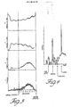
- the voltage signals from the charge amplifiers 28 are passed through a rotary slip ring 30 on the Ferris wheel 10 axis to a chart recorder 32. Examples of the signals generated by the force transducer 24 for the components in the x, y, and z direction are shown in the graphs of Figure 3.
- the time scale runs counter to the usual direction so that the start grinding signal is at the right side of each graph.
- An advantage of the instrumented spindle is that it is in contact with the ceramic part 14 for a period longer than the grinding operation and thus can sense other events that affect the ceramic part.
- the graph of Figure 4 shows the z component of the spindle force throughout a revolution of the Ferris wheel 10. Voltage peaks are measured and events identified for seating the ceramic part 14 on the spindle 12 by an air jet, grinding, unloading and loading. Thus such data can reveal whether any of these functions is the cause of harmful forces.
- a disadvantage is that it is impractical to instrument all of the spindles 12 on the machine because of the size and expense of the charge amplifiers 28. Typically one spindle 12 can be instrumented so that only one out of eighteen parts is subject to the measurements.
- the torque sensor on the control wheel 20 is best shown in Figure 5.
- the control wheel 20 itself comprises a steel hub 38 having an enlarged stepped bore 40, and carries a rubber tyre 42 for contacting the ceramic parts 14.
- a hollow shaft 44 for driving the control wheel 20 is coupled to the control wheel 20 by the torque sensor 46 which is keyed to the hollow shaft 44 and fits within the stepped bore 40 of the hub 38.
- the torque sensor 46 has a flange 48 bolted to the hub 38, and a body 50 keyed to the hollow shaft 44 and coupled to the flange 48 through a load cell (not shown).
- a nut 52 secures the assembly to the hollow shaft 44.
- a cable 54 from the load cell passes through the hollow shaft 44 to a slip ring 56 which allows signals from the torque sensor 46 to be coupled to the chart recorder 32.
- the y-axis forces reflect the radial forces imposed on the spindle 12 by the control wheel 20 and the grinding wheel 22. Since the grinding wheel 22 inherently removes material which would press against it, the chief y-axis force on the spindle is from the control wheel 20. That force increases as the ceramic part 14 enters the grinding zone and reaches a maximum when the ceramic part is closest to the control wheel axis. This occurs at the dwell position when the ceamic part 14 is centred between the control wheel 20 and the grinding wheel 22. The maximum value remains during the dwell period.
- the size and condition of the control wheel 20 can be deduced from the y-axis force, a new control wheel 20 being positioned slightly closer to the ceramic part 14 to yield a higher force and a worn control wheel yielding a lower force.
- the magnitudes of the signals are subject to many material and process parameters and reveal material or process anomalies during grinding. For example if the feed rate is too great for a given ceramic part 14 or for a certain material the signal amplitude will be too high. Similar results are obtained if the control wheel 20 speed is too low. By recognizing this, suitable adjustments can be made in the feed rate or other aspects of the process to avoid forces high enough to break the ceramic parts 14. A feed back control responsive to the torque is also feasible so that automatic changes in the process are made as required to optimize the operation or to shut down the operation if the forces exceed preset limits.
- the subject measuring apparatus is useful in the setup and control of the grinding of spark plug blanks and other ceramic parts 14 and provides an embodiment for three axis force measurement throughout the travel of a part on the Ferris wheel 10 and an embodiment for measuring control wheel 20 torque during every grinding operation to determine the force on each ceramic part and the trend over a number of ceramic parts.
Landscapes
- Engineering & Computer Science (AREA)
- Mechanical Engineering (AREA)
- Constituent Portions Of Griding Lathes, Driving, Sensing And Control (AREA)
- Grinding Of Cylindrical And Plane Surfaces (AREA)
Applications Claiming Priority (2)
| Application Number | Priority Date | Filing Date | Title |
|---|---|---|---|
| US204832 | 1988-06-10 | ||
| US07/204,832 US4860499A (en) | 1988-06-10 | 1988-06-10 | Apparatus for measuring grinding forces on ceramic parts |
Publications (2)
| Publication Number | Publication Date |
|---|---|
| EP0345941A2 true EP0345941A2 (de) | 1989-12-13 |
| EP0345941A3 EP0345941A3 (de) | 1991-01-02 |
Family
ID=22759634
Family Applications (1)
| Application Number | Title | Priority Date | Filing Date |
|---|---|---|---|
| EP19890304395 Withdrawn EP0345941A3 (de) | 1988-06-10 | 1989-05-02 | Gerät zur Messung von Schleifkräften an Keramikteilen |
Country Status (2)
| Country | Link |
|---|---|
| US (1) | US4860499A (de) |
| EP (1) | EP0345941A3 (de) |
Families Citing this family (6)
| Publication number | Priority date | Publication date | Assignee | Title |
|---|---|---|---|---|
| EP0475316A1 (de) * | 1990-09-10 | 1992-03-18 | United Technologies Corporation | Vorrichtung zum Zurichten von Flächen an Gasturbinenschaufeln |
| US5218788A (en) * | 1990-10-09 | 1993-06-15 | K-Line Industries, Inc. | Valve stem polishing method and apparatus |
| DE4342325C2 (de) * | 1993-12-11 | 1999-10-14 | Reika Werk Gmbh Maschf | Verfahren und Vorrichtung zum lage- und maßgenauen Anfasen eines Rohrendes |
| DE102010046392B4 (de) | 2010-09-24 | 2015-02-19 | Rattunde & Co. Gmbh | Bürstentgratemaschine |
| DE102010050317B4 (de) * | 2010-11-05 | 2012-06-14 | Rattunde & Co. Gmbh | Bürstenentgratmaschine |
| CN114619375B (zh) * | 2022-03-22 | 2022-11-25 | 西安交通大学 | 一种磨削力在线测量的砂轮 |
Family Cites Families (9)
| Publication number | Priority date | Publication date | Assignee | Title |
|---|---|---|---|---|
| US2091973A (en) * | 1935-06-27 | 1937-09-07 | Gen Motors Corp | Apparatus for making ceramic articles |
| CA1025695A (en) * | 1967-02-01 | 1978-02-07 | Clarence Hofelt (Jr.) | Means for correcting non-uniformity in tires |
| DE2326046C2 (de) * | 1973-05-22 | 1974-08-29 | Gebr. Hofmann Kg Maschinenfabrik, 6100 Darmstadt | Verfahren und Vorrichtung zur Qualitätsprüfung von Reifen, insbesondere von Kraftfahrzeugreifen |
| DE2906892A1 (de) * | 1979-02-22 | 1980-09-11 | Kurt Manfred Dipl Phys Tischer | Anordnung fuer eine werkzeugueberwachung und -bruchkontrolle mit hilfe von piezoxiden |
| JPS5888631A (ja) * | 1981-11-24 | 1983-05-26 | Yotaro Hatamura | スラスト・トルク検出素子 |
| DE3407620A1 (de) * | 1984-03-01 | 1985-09-12 | Klaus Prof. Dr.-Ing. 4006 Erkrath Brankamp | Vorrichtung zur erfassung einer zwischen zwei gegeneinander bewegbaren maschinenteilen auftretenden kraft |
| US4671147A (en) * | 1985-05-30 | 1987-06-09 | General Electric Company | Instrumented tool holder |
| US4741231A (en) * | 1986-04-14 | 1988-05-03 | The Warner & Swasey Company | Tool force sensor and method of making same |
| GB8610310D0 (en) * | 1986-04-28 | 1986-06-04 | Vickers Plc | Dynamometers |
-
1988
- 1988-06-10 US US07/204,832 patent/US4860499A/en not_active Expired - Fee Related
-
1989
- 1989-05-02 EP EP19890304395 patent/EP0345941A3/de not_active Withdrawn
Also Published As
| Publication number | Publication date |
|---|---|
| EP0345941A3 (de) | 1991-01-02 |
| US4860499A (en) | 1989-08-29 |
Similar Documents
| Publication | Publication Date | Title |
|---|---|---|
| US6086452A (en) | Method of high speed centrifugal run-out grinding of a pneumatic tire | |
| US3739533A (en) | Method for optimizing tire uniformity | |
| US3724137A (en) | Means for correcting non-uniformity in tires | |
| US6139401A (en) | Method of correcting the imbalance of a pneumatic tire with a tire uniformity machine | |
| US3914907A (en) | Method for improving the ride characteristics of tires | |
| US5614676A (en) | Method of machine vibration analysis for tire uniformity machine | |
| US4173850A (en) | Method for reducing tangential force variation in pneumatic tires | |
| US3841033A (en) | Tire manufacturing | |
| CA1293555C (en) | Tire uniformity correction | |
| KR970001974B1 (ko) | 타이어의 균일성을 수정하기 위한 방법 및 장치 | |
| US4041647A (en) | Apparatus for improving tire uniformity | |
| US4860499A (en) | Apparatus for measuring grinding forces on ceramic parts | |
| JPS6123105B2 (de) | ||
| US3543576A (en) | Tire testing apparatus and method | |
| US3963427A (en) | Method for improving tire uniformity | |
| CA1287148C (en) | Tire uniformity machine | |
| US4128969A (en) | Apparatus for reducing tangential force variation in pneumatic tires | |
| JPH08193879A (ja) | ロール研削盤の研削異常の検出方法 | |
| JPH0929630A (ja) | 表面研削方法 | |
| WO1998005937A1 (en) | Method of high speed centrifugal run-out grinding of a pneumatic tire | |
| US3116632A (en) | Apparatus and method of grading grinding wheels in rotation | |
| KR100411797B1 (ko) | 타이어 비드부의 접촉압력 측정장치 | |
| JP3821396B2 (ja) | 力変動機械の適応ウォームアップ法 | |
| JPS629867A (ja) | 研削装置 | |
| WO1998016810A1 (en) | Method of correcting the imbalance of a pneumatic tire with a tire uniformity machine |
Legal Events
| Date | Code | Title | Description |
|---|---|---|---|
| PUAI | Public reference made under article 153(3) epc to a published international application that has entered the european phase |
Free format text: ORIGINAL CODE: 0009012 |
|
| AK | Designated contracting states |
Kind code of ref document: A2 Designated state(s): DE FR GB |
|
| PUAL | Search report despatched |
Free format text: ORIGINAL CODE: 0009013 |
|
| AK | Designated contracting states |
Kind code of ref document: A3 Designated state(s): DE FR GB |
|
| 17P | Request for examination filed |
Effective date: 19910219 |
|
| 17Q | First examination report despatched |
Effective date: 19920604 |
|
| STAA | Information on the status of an ep patent application or granted ep patent |
Free format text: STATUS: THE APPLICATION IS DEEMED TO BE WITHDRAWN |
|
| 18D | Application deemed to be withdrawn |
Effective date: 19921201 |