EP0345630A2 - Automatic coupling - Google Patents
Automatic coupling Download PDFInfo
- Publication number
- EP0345630A2 EP0345630A2 EP89109894A EP89109894A EP0345630A2 EP 0345630 A2 EP0345630 A2 EP 0345630A2 EP 89109894 A EP89109894 A EP 89109894A EP 89109894 A EP89109894 A EP 89109894A EP 0345630 A2 EP0345630 A2 EP 0345630A2
- Authority
- EP
- European Patent Office
- Prior art keywords
- screw
- calibration
- adapter sleeve
- ring
- automatic coupling
- Prior art date
- Legal status (The legal status is an assumption and is not a legal conclusion. Google has not performed a legal analysis and makes no representation as to the accuracy of the status listed.)
- Withdrawn
Links
Images
Classifications
-
- B—PERFORMING OPERATIONS; TRANSPORTING
- B29—WORKING OF PLASTICS; WORKING OF SUBSTANCES IN A PLASTIC STATE IN GENERAL
- B29C—SHAPING OR JOINING OF PLASTICS; SHAPING OF MATERIAL IN A PLASTIC STATE, NOT OTHERWISE PROVIDED FOR; AFTER-TREATMENT OF THE SHAPED PRODUCTS, e.g. REPAIRING
- B29C45/00—Injection moulding, i.e. forcing the required volume of moulding material through a nozzle into a closed mould; Apparatus therefor
- B29C45/17—Component parts, details or accessories; Auxiliary operations
- B29C45/1775—Connecting parts, e.g. injection screws, ejectors, to drive means
Definitions
- the invention relates to an automatic coupling for a rotatable and axially movable screw of an exchangeable plasticizing unit of an injection molding machine with the machine-side drive device of the injection molding machine, with a driving ring for the transmission of force between the screw guided in the mass cylinder of the plasticizing unit and the drive device.
- Coupling devices that can be released automatically are disproportionately complex and prone to failure according to the known prior art.
- the object of the invention is to provide an automatic clutch of the type mentioned, which enables simple automatic rapid separation of the screw from the drive device or coupling of the screw to the drive device, and wherein a conventional standard screw in a simple manner can be provided with a calibration device.
- the object of the invention is achieved in that the worm is positively and / or non-positively connected to an adapter sleeve which carries a calibration ring on which at least one calibrator can be moved radially to the worm beam attacks.
- the adapter sleeve engages in a fixed bearing bell on the clamping elements of the injection molding machine, is rotatably held.
- An embodiment of the invention provides that the driver ring with the screw and / or the adapter sleeve is positively and / or non-positively connected and that the drive shaft of the drive device has a centering and stop pin which projects into the driver ring.
- the calibration bar is guided in a calibration center attached to the mass cylinder.
- the calibration bar engages the calibration ring during the engagement or disengagement process and that the tensioning elements are preferably wedges which act on spring tension and engage a tensioning flange of the bearing bell.
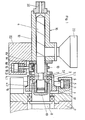
- FIG. 1 shows an axial section through the coupling according to the invention and parts of the plasticizing unit and the drive device in the engaged position
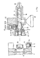
- FIG. 2 shows a similar section in the disengaged position.
- the parts belonging to the plasticizing unit 16 are the mass cylinder 12, the screw 4, the adapter sleeve 3, the driving ring 9 and the bearing bell 1.
- the screw 4 located in the plasticizing unit 16, as well as the adapter sleeve 3, the driver 9, the bearing bell 1, the radial axial bearing 2 and the calibration ring 13 form a fixed, assembled unit.
- the adapter sleeve 3 can be formed by two half-shells screwed together. Another embodiment provides that the adapter sleeve 3 in the area 3.1 and the screw 4 in the area 4.2 are provided with intermeshing splined shaft profiles. During assembly, the adapter sleeve 3 is pushed with its splined shaft profile on the splined shaft profile of the worm 4 and then rotated by 15 o. As a result, the adapter sleeve 3 is fixed on the screw 4 in the axial direction.
- the bearing bell 1 is mounted on the adapter sleeve 3 via an axial and radial bearing 2.
- the adapter sleeve 3 is connected to an annular groove 4.1 on the screw 4 in a positive and / or non-positive manner. This connection makes it possible to transmit axial forces and movements to the worm 4 from the drive shaft 8 via the adapter sleeve 3.
- the driving ring 9 is positively or non-positively connected to the worm 4 and the adapter sleeve 3 and positively to the drive shaft 8 or the stop pin 10.
- the driver ring 9 is formed with two lateral, central, parallel surfaces (so-called key surfaces), which are received in a form-fitting manner in the drive shaft 8.
- the drive shaft 8 is slit open at the front. Due to this positive locking, it is now possible to transmit torque.
- the centering and stop pin is primarily used to transmit one-sided axial forces (injection force) and secondarily to center the concentricity of the screw unit.
- the connection of the driving ring 9 with the worm 4 serves to transmit the torque.
- the connection of the driving ring 9 with the adapter sleeve 3 serves as an anti-rotation device for the adapter sleeve 3 and as a loss protection for the driving ring 9 itself if the plasticizing unit 16 has to be transported.
- the driving ring 9 is connected to the adapter sleeve 3 by means of screws.
- the bearing bell 1 is held by the attack of self-locking wedges 6, which are acted upon by springs 5.
- the wedges 6 are mounted on the machine side on the drive device 7 and engage a holding flange 17 of the bearing bell 1.
- the screw unit 1, 2, 3, 4, 9 is held in a precisely defined longitudinal position relative to the mass cylinder, i.e. calibrated.
- a calibration ring 13 is positively and / or non-positively fastened on the adapter sleeve 3.
- the adapter sleeve 3 has an external thread onto which the calibration ring 13 is screwed.
- the calibration ring 13 is held in a positive and / or non-positive manner in the calibration center 15 attached to the mass cylinder 12 during the coupling process by means of a calibration bar 14 which can be moved radially relative to the screw 4.
- the calibration bar 14 is displaced against the force of the spring 18 by a hydraulic fluid acting on the piston 19.
- the reverse construction is of course also possible. That is, instead of the calibration ring 13, the adapter sleeve 3 could have an annular groove into which a projection of the calibration bar 14 engages.
- the cylinders 21 for the calibration bar 14, the cylinder plate 2 and the measuring funnel 23 are also shown in the figures of the drawings.
Landscapes
- Engineering & Computer Science (AREA)
- Manufacturing & Machinery (AREA)
- Mechanical Engineering (AREA)
- Injection Moulding Of Plastics Or The Like (AREA)
Abstract
Description
Die Erfindung bezieht sich auf eine automatische Kupplung für eine dreh- und axialbewegbare Schnecke einer auswechselbaren Plastifiziereinheit einer Spritzgießmaschine mit der maschinenseitigen Antriebsvorrichtung der Spritzgießmaschine, mit einem Mitnehmerring für die Kraftübertragung zwischen der im Massezylinder der Plastifiziereinheit geführten Schnecke und der Antriebsvorrichtung.The invention relates to an automatic coupling for a rotatable and axially movable screw of an exchangeable plasticizing unit of an injection molding machine with the machine-side drive device of the injection molding machine, with a driving ring for the transmission of force between the screw guided in the mass cylinder of the plasticizing unit and the drive device.
Bei Kupplungen zwischen der Schnecke und der Antriebsvorrichtung sind für die Drehübertragung üblicherweise Mehrkant- oder Keilwellenprofile vorgesehen, die einen Formschluß herstellen und die Übertragung der axialen Zug- oder Druckkräfte erfolgt meist über Zuganker oder dergleichen. Soll die Schnecke ausgetauscht werden, müssen die Kupplungsteile von Hand ausgelöst werden, was zeitaufwendig ist und daher zu unerwünschten Stehzeiten der Spritzgießmaschine führt.In the case of couplings between the worm and the drive device, polygonal or splined shaft profiles are usually provided for the rotation transmission, which produce a positive connection and the transmission of the axial tensile or compressive forces is usually carried out via tie rods or the like. If the screw is to be replaced, the coupling parts have to be released by hand, which is time-consuming and therefore leads to undesirable downtimes of the injection molding machine.
Kupplungsvorrichtungen, die automatisch lösbar sind, sind nach dem bekannten Stand der Technik unverhältnismäßig aufwendig und störanfällig.Coupling devices that can be released automatically are disproportionately complex and prone to failure according to the known prior art.
Aufgabe der Erfindung ist es, eine automatische Kupplung der eingangs erwähnten Art zu schaffen, die mit einfachen Mitteln eine schnelle automatische Trennung der Schnecke von der Antriebsvorrichtung bzw. Kupplung der Schnecke mit der Antriebsvorrichtung ermöglicht, und wobei eine herkömmliche Standardschnecke auf einfache Art und Weise mit einer Kalibriervorrichtung versehen werden kann.The object of the invention is to provide an automatic clutch of the type mentioned, which enables simple automatic rapid separation of the screw from the drive device or coupling of the screw to the drive device, and wherein a conventional standard screw in a simple manner can be provided with a calibration device.
Die erfindungsgemäße Aufgabe wird dadurch gelöst, daß die Schnecke mit einer Adapterhülse form- und/oder kraftschlüssig verbunden ist, die einen Kalibrierring trägt, an dem mindestens ein zur Schnecke radial bewegbarer Kalibrier balken angreift.The object of the invention is achieved in that the worm is positively and / or non-positively connected to an adapter sleeve which carries a calibration ring on which at least one calibrator can be moved radially to the worm beam attacks.
Vorteilhaft ist vorgesehen, daß die Adapterhülse in einer feststehenden Lagerglocke an der Spannelemente der Spritzgießmaschine angreifen, drehbar gehalten ist.It is advantageously provided that the adapter sleeve engages in a fixed bearing bell on the clamping elements of the injection molding machine, is rotatably held.
Ein Ausführungsbeispiel der Erfindung sieht vor, daß der Mitnehmerring mit der Schnecke und/oder der Adapterhülse form- und/oder kraftschlüssig verbunden ist und daß die Antriebswelle der Antriebsvorrichtung einen Zentrier- und Anschlagbolzen aufweist, der in den Mitnehmerring ragt.An embodiment of the invention provides that the driver ring with the screw and / or the adapter sleeve is positively and / or non-positively connected and that the drive shaft of the drive device has a centering and stop pin which projects into the driver ring.
Weiters ist vorgesehen, daß der Kalibrierbalken in einer am Massezylinder befestigten Kalibrierzentrierung geführt ist.It is also provided that the calibration bar is guided in a calibration center attached to the mass cylinder.
In einem weiteren Ausführungsbeispiel der Erfindung ist vorgesehen, daß der Kalibrierbalken während des Ein- bzw. Auskupplungsvorganges den Kalibrierring greift und daß die Spannelemente vorzugsweise durch Federkraft beaufschlagte Keile sind, die an einem Spannflansch der Lagerglocke angreifen.In a further embodiment of the invention, it is provided that the calibration bar engages the calibration ring during the engagement or disengagement process and that the tensioning elements are preferably wedges which act on spring tension and engage a tensioning flange of the bearing bell.
Nachfolgend wird ein Ausführungsbeispiel der Erfindung anhand der Figuren der Zeichnungen eingehend beschrieben.An exemplary embodiment of the invention is described in detail below with reference to the figures in the drawings.
Die Fig. 1 zeigt einen Axialschnitt durch die erfindungsgemäße Kupplung und Teile der Plastifiziereinheit und der Antriebsvorrichtung in der eingekuppelten Stellung und die Fig. 2 zeigt einen gleichen Schnitt in der ausgekuppelten Stellung.1 shows an axial section through the coupling according to the invention and parts of the plasticizing unit and the drive device in the engaged position, and FIG. 2 shows a similar section in the disengaged position.
Die nicht unmittelbar zur Erfindung gehörenden Teile der Spritzgießmaschine werden in der nachfolgenden Beschreibung nicht behandelt, da sie nach dem bekannten Stand der Technik ausgeführt sind.The parts of the injection molding machine that are not directly part of the invention are not dealt with in the following description, since they are designed according to the known prior art.
Die in der Plastifiziereinheit 16 zugehörigen Teile sind der Massezylinder 12, die Schnecke 4, die Adapterhülse 3, der Mitnehmerring 9 und die Lagerglocke 1. Die in der Plastifiziereinheit 16 befindliche Schnecke 4, sowie die Adapterhülse 3, der Mitnehmer 9, die Lagerglocke 1, die Radial-Axiallagerung 2 und der Kalibrierring 13 bilden eine fixe, zusammenmontierte Einheit.The parts belonging to the plasticizing
Die Adapterhülse 3 kann von zwei zusammengeschraubten Halbschalen gebildet werden. Eine andere Ausführungsform sieht vor, daß die Adapterhülse 3 im Bereich 3.1 und die Schnecke 4 im Bereich 4.2 mit ineinander greifenden Vielkeilwellenprofilen versehen sind. Bei der Montage wird die Adapterhülse 3 mit ihrem Vielkeilwellenprofil über das Vielkeilwellenprofil der Schnecke 4 geschoben und anschließend um 15o verdreht. Dadurch ist die Adapterhülse 3 auf der Schnecke 4 in axialer Richtung fixiert.The
Maschinenseitig gelagert, d.h. der Antriebseinheit 7 zugehörig, sind die Antriebswelle 8, der Anschlagbolzen 10 und die Keile 6. Diese Teile sind ebenfalls eine fixe, zusammenmontierte Einheit.Stored on the machine side, i.e. belonging to the
Die Lagerglocke 1 ist über ein Axial- und Radiallager 2 auf der Adapterhülse 3 gelagert. Die Adapterhülse 3 ist mit einer Ringnut 4.1 an der Schnecke 4 form- und/oder kraftschlüssig verbunden. Diese Verbindung ermöglicht es, von der Antriebswelle 8 über die Adapterhülse 3 axiale Kräfte und Bewegungen auf die Schnecke 4 zu übertragen.The
Zur Übertragung des erforderlichen Drehmomentes von der Antriebswelle 8 auf die Schnecke 4 wird der Mitnehmerring 9 form- oder kraftschlüssig mit der Schnecke 4, sowie der Adapterhülse 3 verbunden und formschlüssig mit der Antriebswelle 8 bzw. dem Anschlagbolzen 10. Der form- und/oder kraftschlüssig mit der Antriebswelle 8 verbundene Zentrier- und Anschlagbolzen 10 greift in den Mitnehmerring 9 ein und stellt die Zentrizität zwischen der Schneckeneinheit 1,2, 3,4,9 und der Antriebseinheit 7,8 her.To transmit the required torque from the
Der Mitnehmerring 9 ist mit zwei seitlichen, zentrischen parallelen Flächen (sogenannten Schlüsselflächen) ausgebildet, welche in der Antriebswelle 8 formschlüssig aufgenommen werden. Dafür wird die Antriebswelle 8 gabelförmig, stirnseitig aufgeschlitzt. Durch diesen Formschluß ist es nun möglich, Drehkräfte zu übertragen. Der Zentrier- und Anschlagbolzen dient primär zur Übertragung von einseitigen Axialkräften (Einspritzkraft) und sekundär zur Rundlaufzentrierung der Schneckeneinheit. Die Verbindung des Mitnehmerringes 9 mit der Schnecke 4 dient der Drehmomentenübertragung. Die Verbindung des Mitnehmerringes 9 mit der Adapterhülse 3 dient als Verdrehsicherung für die Adapterhülse 3 und als Verliersicherung für den Mitnehmerring 9 selbst, falls die Plastifiziereinheit 16 transportiert werden muß. Der Mitnehmerring 9 ist mit der Adapterhülse 3 mittels Schrauben verbunden.The
Die Lagerglocke 1 wird durch den Angriff selbsthemmender Keile 6, die von Federn 5 beaufschlagt sind, gehalten. Die Keile 6 sind dabei maschinenseitig an der Antriebsvorrichtung 7 gelagert und greifen an einem Halteflansch 17 der Lagerglocke 1 an.The
Durch den Angriff der Keile 6 an der Lagerglocke 1 und dadurch, daß die Adapterhülse 3 in der Lagerglocke 1 geführt und gehalten ist, ist eine konzentrische, spielfreie, axiale sowie radiale Verbindung der Schneckeneinheit mit der maschinenseitigen Antriebseinheit 7 hergestellt.By attacking the
Zum Lösen dieser Verbindung werden die mit den Keilen 6 verbundenen Kolben 11 an den Kolbenringflächen mittels einer Hydraulikflüssigkeit soweit angehoben, daß der Eingriff zwischen den Keilen 6 und der Lagerglocke 1 aufgehoben ist, wodurch die Verbindung zwischen der Schneckeneinheit 1,2,3,4,9 und der Antriebseinheit 7,8 gelöst ist.To release this connection, use the
Um den automatischen Kupplungsvorgang zu vereinfachen und zu beschleunigen, wird die Schneckeneinheit 1,2,3,4,9 in einer genau definierten Längsposition zum Massezylinder festgehalten, d.h. kalibriert. Zu diesem Zweck ist auf der Adapterhülse 3 ein Kalibrierring 13 form- und/oder kraftschlüssig befestigt. Beispielsweise weist die Adapterhülse 3 ein Außengewinde auf, auf das der Kalibrierring 13 aufgeschraubt ist. Der Kalibrierring 13 wird während des Kupplungsvorganges durch einen radial zur Schnecke 4 bewegbaren Kalibrierbalken 14 in einer am Massezylinder 12 befestigten Kalibrierzentrierung 15 form- und/oder kraftschlüssig festgehalten. Der Kalibrierbalken 14 wird dabei entgegen der Kraft der Feder 18 durch eine am Kolben 19 angreifende Hydraulikflüssigkeit verschoben.In order to simplify and accelerate the automatic coupling process, the
Anstelle des Kalibrierringes 13 und des gabelförmigen Kalibrierbalkens 14 wird natürlich auch die umgekehrte Konstruktion möglich. Das heißt, die Adapterhülse 3 könnte anstatt des Kalibrierringes 13 eine Ringnut aufweisen, in die ein Vorsprung des Kalibrierbalkens 14 eingreift.Instead of the
Bei einer Bewegung der Spritzeinheit (Antriebseinheit 7,8) wird auch die komplette Schneckeneinheit 1,2,3,4,9 nach rechts mitgezogen, wobei sich die Schnecke 4 am Anschlag- und Zentrierbolzen 10 abstützt und die Lagerglocke 1 über die Keile 6 spielfrei und mit Vorspannung auch in Richtung der Spritzeinheit (Antriebsvorrichtung 7 und Antriebswelle 8) gedrückt wird.When the injection unit (
In den Figuren der Zeichnungen sind noch die Zylinder 21 für den Kalibrierbalken 14, die Zylinderplatte 2 und die Meßtrichter 23 eingezeichnet.The
Claims (7)
Applications Claiming Priority (2)
| Application Number | Priority Date | Filing Date | Title |
|---|---|---|---|
| AT147088A AT390910B (en) | 1988-06-07 | 1988-06-07 | AUTOMATIC CLUTCH |
| AT1470/88 | 1988-06-07 |
Publications (2)
| Publication Number | Publication Date |
|---|---|
| EP0345630A2 true EP0345630A2 (en) | 1989-12-13 |
| EP0345630A3 EP0345630A3 (en) | 1991-06-05 |
Family
ID=3514601
Family Applications (1)
| Application Number | Title | Priority Date | Filing Date |
|---|---|---|---|
| EP19890109894 Withdrawn EP0345630A3 (en) | 1988-06-07 | 1989-06-01 | Automatic coupling |
Country Status (2)
| Country | Link |
|---|---|
| EP (1) | EP0345630A3 (en) |
| AT (1) | AT390910B (en) |
Cited By (2)
| Publication number | Priority date | Publication date | Assignee | Title |
|---|---|---|---|---|
| EP1074335A3 (en) * | 1999-07-08 | 2002-05-22 | Meltog Limited | Mandrel and tooling replacement and apparatus therefor |
| WO2020041886A1 (en) | 2018-08-30 | 2020-03-05 | Husky Injection Molding Systems Ltd. | Melt dispenser for plastic molding |
Families Citing this family (1)
| Publication number | Priority date | Publication date | Assignee | Title |
|---|---|---|---|---|
| AT521960B1 (en) | 2019-01-11 | 2020-07-15 | Engel Austria Gmbh | Coupling element |
Citations (1)
| Publication number | Priority date | Publication date | Assignee | Title |
|---|---|---|---|---|
| DE3229223A1 (en) * | 1981-09-28 | 1983-04-07 | Netstal-Maschinen AG, 8752 Näfels | Clutch device between drive device and screw of the plastication unit of an injection moulding machine |
-
1988
- 1988-06-07 AT AT147088A patent/AT390910B/en not_active IP Right Cessation
-
1989
- 1989-06-01 EP EP19890109894 patent/EP0345630A3/en not_active Withdrawn
Patent Citations (1)
| Publication number | Priority date | Publication date | Assignee | Title |
|---|---|---|---|---|
| DE3229223A1 (en) * | 1981-09-28 | 1983-04-07 | Netstal-Maschinen AG, 8752 Näfels | Clutch device between drive device and screw of the plastication unit of an injection moulding machine |
Cited By (6)
| Publication number | Priority date | Publication date | Assignee | Title |
|---|---|---|---|---|
| EP1074335A3 (en) * | 1999-07-08 | 2002-05-22 | Meltog Limited | Mandrel and tooling replacement and apparatus therefor |
| WO2020041886A1 (en) | 2018-08-30 | 2020-03-05 | Husky Injection Molding Systems Ltd. | Melt dispenser for plastic molding |
| CN113195195A (en) * | 2018-08-30 | 2021-07-30 | 赫斯基注塑系统有限公司 | Melt distributor for plastic molding |
| EP3843970A4 (en) * | 2018-08-30 | 2022-06-29 | Husky Injection Molding Systems Luxembourg IP Development S.à.r.l | Melt dispenser for plastic molding |
| CN113195195B (en) * | 2018-08-30 | 2023-03-10 | 赫斯基注塑系统有限公司 | Melt distributor for plastic molding |
| US11981062B2 (en) | 2018-08-30 | 2024-05-14 | Husky Injection Molding Systems Ltd | Melt dispenser for plastic molding |
Also Published As
| Publication number | Publication date |
|---|---|
| ATA147088A (en) | 1990-01-15 |
| AT390910B (en) | 1990-07-25 |
| EP0345630A3 (en) | 1991-06-05 |
Similar Documents
| Publication | Publication Date | Title |
|---|---|---|
| DE3545651C2 (en) | ||
| DE69810413T2 (en) | Device for holding, positioning or clamping | |
| DE3626851C2 (en) | Fastening device for rotary grinding tools, in particular grinding wheels, on a spindle | |
| EP0816703B1 (en) | Conical screw connection for lamellae shaft coupling | |
| DE2729939C3 (en) | Power operated chuck | |
| DE935875C (en) | Center clamping jaw chuck for lathe or the like. | |
| DE3403603A1 (en) | FORCE-CONTROLLED NEEDLE CLOSURE FOR INJECTION NOZZLES IN INJECTION MOLDS | |
| EP0155539A1 (en) | Tool device with an exchangeable cutting tool | |
| EP0343347A1 (en) | Tool turret | |
| DE19636594A1 (en) | Release unit | |
| EP0714749A2 (en) | Apparatus for removing moulded articles | |
| EP0345630A2 (en) | Automatic coupling | |
| DE2234321B1 (en) | Dental handpiece | |
| DE3300227A1 (en) | Device for the releasable connection of feed-bar parts of the feed bars in a transfer press | |
| EP0040808A1 (en) | Roll | |
| EP0244667A2 (en) | Device for the exchangeable attachment of a chuck onto the spindle of a machine tool | |
| EP0595200B1 (en) | Coupling decive for a plastic injection moulding machine | |
| DE3729093C1 (en) | Clamping device with mechanical power amplifier | |
| DE851579C (en) | Device for eliminating the axial play of gearboxes | |
| DE1602825B2 (en) | DEVICE FOR DETACHABLE FASTENING OF A CHUCK | |
| EP1152856A1 (en) | Device for detachably connecting a tool | |
| DE4124152A1 (en) | Engaging and disengaging shaft coupling - has inclined guides on the coupling part and insert funnel on coupling sleeve | |
| DE102014101415B3 (en) | jig | |
| DE3533623A1 (en) | Control drive for a control rod in a rotating machine spindle | |
| DE3328397A1 (en) | Coupling device for the torque transmitting connection of two shafts |
Legal Events
| Date | Code | Title | Description |
|---|---|---|---|
| PUAI | Public reference made under article 153(3) epc to a published international application that has entered the european phase |
Free format text: ORIGINAL CODE: 0009012 |
|
| AK | Designated contracting states |
Kind code of ref document: A2 Designated state(s): AT BE CH DE FR GB IT LI NL SE |
|
| PUAL | Search report despatched |
Free format text: ORIGINAL CODE: 0009013 |
|
| AK | Designated contracting states |
Kind code of ref document: A3 Designated state(s): AT BE CH DE FR GB IT LI NL SE |
|
| STAA | Information on the status of an ep patent application or granted ep patent |
Free format text: STATUS: THE APPLICATION IS DEEMED TO BE WITHDRAWN |
|
| 18D | Application deemed to be withdrawn |
Effective date: 19911206 |