EP0345095A2 - Adjustable terminal block equipment - Google Patents
Adjustable terminal block equipment Download PDFInfo
- Publication number
- EP0345095A2 EP0345095A2 EP89305614A EP89305614A EP0345095A2 EP 0345095 A2 EP0345095 A2 EP 0345095A2 EP 89305614 A EP89305614 A EP 89305614A EP 89305614 A EP89305614 A EP 89305614A EP 0345095 A2 EP0345095 A2 EP 0345095A2
- Authority
- EP
- European Patent Office
- Prior art keywords
- terminal blocks
- row
- terminals
- terminal
- formations
- Prior art date
- Legal status (The legal status is an assumption and is not a legal conclusion. Google has not performed a legal analysis and makes no representation as to the accuracy of the status listed.)
- Withdrawn
Links
Images


Classifications
-
- H—ELECTRICITY
- H01—ELECTRIC ELEMENTS
- H01R—ELECTRICALLY-CONDUCTIVE CONNECTIONS; STRUCTURAL ASSOCIATIONS OF A PLURALITY OF MUTUALLY-INSULATED ELECTRICAL CONNECTING ELEMENTS; COUPLING DEVICES; CURRENT COLLECTORS
- H01R9/00—Structural associations of a plurality of mutually-insulated electrical connecting elements, e.g. terminal strips or terminal blocks; Terminals or binding posts mounted upon a base or in a case; Bases therefor
- H01R9/22—Bases, e.g. strip, block, panel
- H01R9/24—Terminal blocks
- H01R9/2408—Modular blocks
-
- H—ELECTRICITY
- H01—ELECTRIC ELEMENTS
- H01R—ELECTRICALLY-CONDUCTIVE CONNECTIONS; STRUCTURAL ASSOCIATIONS OF A PLURALITY OF MUTUALLY-INSULATED ELECTRICAL CONNECTING ELEMENTS; COUPLING DEVICES; CURRENT COLLECTORS
- H01R12/00—Structural associations of a plurality of mutually-insulated electrical connecting elements, specially adapted for printed circuits, e.g. printed circuit boards [PCB], flat or ribbon cables, or like generally planar structures, e.g. terminal strips, terminal blocks; Coupling devices specially adapted for printed circuits, flat or ribbon cables, or like generally planar structures; Terminals specially adapted for contact with, or insertion into, printed circuits, flat or ribbon cables, or like generally planar structures
- H01R12/50—Fixed connections
- H01R12/51—Fixed connections for rigid printed circuits or like structures
- H01R12/515—Terminal blocks providing connections to wires or cables
Definitions
- the present invention relates to electrical terminal blocks, separately and as part of electrical apparatus.
- the terminal blocks in that patent have circuit connectors, each having wire grippers at its opposite ends. Wires from a piece of circuit equipment enter one set of wire grippers at one side of the assembled terminal blocks. The wire grippers at the opposite side of the terminal block assembly are available for making external wired connections.
- a long terminal strip has a row of many terminals at one side for plug-in or soldered connection to corresponding equipment terminals and it has wire grippers at its opposite side.
- the spacing between each of the plug-in or solder terminals, and the overall length of a row of those terminals must match the spacing and overall extent of the equipment terminals.
- Different lengths of terminal strips may be manufactured for various units of electrical equipment. The same range of different lengths of terminal strips may be required for electrical equipment having either of two standards of modular spacing of a row of terminals, one range of various terminal strips in an inch-based system and another range of terminal strips in a millimeter-based system.
- the present invention adapts a single form of terminal block or circuit connecting device to both inch-based and millimeter-based modular terminal configurations of the electrical equipment.
- a single terminal block contains two circuit connectors, and those connectors have pin terminals whose spacing is fixed.
- the pin terminals are intended to mate with close-spaced equipment terminals.
- Usual tolerances of the equipment terminal pattern and the pin terminals of the terminal block are such that there may be no problem of the pin terminals mating with the equipment terminals, even if the modular standard of the terminal block is inch-based and the modular standard of the equipment terminals is millimeter-based.
- a terminal block assembly in either modular system may introduce a deviation of many times 0.08 mm (0.003 inch) when used with electrical equipment having a terminal configuration based on the opposite modular system.
- the present invention provides modular terminal blocks or connecting devices in a row or multiple parallel rows that are held together in an assembly but in which the length of the row(s) is variable to a limited extent to accommodate both inch-based modular spacing and millimeter-based modular spacing of the terminals at one side of the assembly.
- the present invention provides assembled terminal blocks in a row or rows wherein the distribution of the circuit connectors of a row is precisely fixed by a unifying member or members so that all the terminals of the terminal block assembly are aligned with terminals of the electrical equipment.
- the invention provides assembled electrical apparatus that includes electrical equipment having at least one row of terminals, in combination with an assembled row or rows of terminal blocks wherein each terminal block has no more than a few circuit connectors, the assembled terminal blocks having terminals distributed in a row or rows and having one or more unifying members that establish a distribution of the circuit connectors that corresponds to the distribution of the terminals of the electrical equipment.
- the assembled terminal blocks have circuit connectors each of which has a screw-fastener and a projecting pin terminal; and because the distribution of each row of pin terminals is fixed by a unifying member or members in accordance with inch-based or millimeter-based standards, the assembled terminal blocks provide a pattern of pin terminals that mate directly with a corresponding modular pattern of inch-based or millimeter-based equipment terminals.
- Figs. 1-3 represent a terminal block assembly for making wire connections to a pattern of terminals of electrical equipment represented in Fig. 9, e.g., the printed circuit board in Fig. 3.
- the equipment terminals can accommodate only limited misalignment (e.g. about 0.08 mm (three-thousandths of an inch)) with the terminals of the terminal block assembly.
- the illustrative terminal block assembly includes three rows of modular terminal blocks 10, 12 and 14.
- each row of terminal blocks comprises six terminal blocks each of which has two circuit connectors, so that there are twelve connectors in each row.
- each connector in this example provides a pin terminal and wire fastener, for connecting a wire to an equipment terminal.
- a typical circuit connector (Fig. 3) includes a stationary conductor 16 having a horizontal contact portion 16a, a downward projecting pin terminal 16b and a resilient detent 16c.
- Contact portion 16a extends between the top and bottom walls and between the side walls of a four-wall clamp 18.
- Screw 20 extends through the threaded double-thick top wall of clamp 18. The lower end of screw 20 bears against the top of contact portion 16a. As the screw is tightened, it draws the bottom wall or jaw of clamp 18 upward, so that an inserted wire is gripped between the clamp's jaw and contact portion 16a.
- This form of screw-operated clamp and stationary contact constitutes an excellent, well-known form of wire gripper.
- Each terminal block 22 of row 10 includes two connectors 16, 18, 20 which are entirely contained in a body of molded insulation 24 except for projecting pin terminal 16b.
- Detent 16c is received in a hole 24a in the insulating body, holding conductor 16 in place.
- a wire enters the connector via an opening 24b.
- Rows of terminal blocks 26 and 28 behind row 22 are successively taller than terminal blocks 22.
- Terminal blocks 26 and 28 have the same construction as terminal block 22, except for their different heights.
- the parts of all the terminal blocks that are identical bear the same numerals, while corresponding parts that are different bear the same numerals, distinguished by (′) and ( ⁇ ).
- circuit wires can extend over terminal blocks 22 for insertion into respective openings 24b of terminal blocks 26. Each inserted wire is gripped by screw-operated clamp 18 and contact portion 16a of a connector in block 26.
- Each conductor 16′ in blocks 26 is elongated, to reach its projecting pin terminal 16b′.
- terminal blocks 28 of row 14 have openings 24b at the left (Fig. 3) so that wires can extend over terminal blocks 26 and into terminal blocks 28, to be gripped by parts 16 ⁇ and 18 of those terminal blocks.
- Conductors 16 ⁇ of terminal blocks 28 are long enough to reach pin terminals 16b ⁇ that project downward from the common bottom plane of all three rows of terminal blocks.
- terminal block 26 at the left end of row 12 is offset in relation to the terminal block 22 at the left end of row 10. All of the other terminal blocks of these two rows are offset correspondingly.
- the connectors contained in the terminal blocks 26 of row 12 are correspondingly offset from the two connectors in the terminal blocks 22 of row 10.
- One benefit of this offset relationship is that wiring is made easier. Wires entering terminal blocks 26 do not obstruct access to screws 20 of the connectors of terminal blocks 22. Terminal blocks 26 of row 12 are also offset relative to terminal blocks 28 of row 14, with the resulting ease of wiring. Wires entering any terminal block 28 do not obstruct access to screws 20 of terminal blocks 26. While wires entering terminal blocks 28 may extend over screws 20 of terminal blocks 22, blocks 28 are so much taller than blocks 22 that access to the screws of the shorter blocks 22 is not difficult.
- the left-hand terminal blocks 22 and 26 are unified by a dovetail joint 30 (Figs. 1 and 3) and the left-hand terminal blocks 26 and 28 are also unified by a dovetail joint 30.
- These dovetail joints constitute formations that unify the terminal blocks of the three rows 10, 12 and 14 in groups of three.
- row 14 can be omitted. Blocks 22 and 26 remain unified in pairs. As another option, row 12 could be omitted, and in that event, the terminal blocks 28 would be aligned with terminal blocks 22 and unified in pairs by their dovetail joints 30.
- the terminal blocks of each row are movable toward and away from each other to a limited extent, and the groups of three unified terminal blocks 22, 26 and 28 (as well as unified pairs) are correspondingly movable toward and away from each other to a limited extent.
- This controlled limited movement results from interlocking formations 32 of blocks 22 and 26 and interlocking formations 34 of terminal blocks 26 and 28.
- Each of these interlocking formations involves what may be called a spline on one block that is received in a generally complementary groove in the other.
- the dimensions of the spline are narrower than the corresponding dimensions of the groove, in the direction parallel to the lengths of the rows.
- each block of each row, and each group of unified blocks is movable toward and away from its neighboring or next-adjacent block(s) or group(s).
- the end blocks of each row of course, have only one next-adjacent block and they are movable toward and away from only one next-adjacent block; hence the terms "block(s)” and "group(s)” are useful.
- T-shaped interlocking formations that allow limited lengthening and contraction of each row of terminal blocks, as well as lengthening and contraction of all the rows of blocks, might be simple ribs that only limit such lengthening and contraction.
- their cross-section is T-shaped.
- the wide portion of the groove in one block that receives the cross-bar of the "T" is wider (horizontally, Fig. 1) than the length of the cross-bar, and the slot of that groove which receives the center bar of the "T" is wider than that center bar.
- the T-shaped formations allow limited movement -- e.g. 0.012 inch -- of each terminal block relative to its neighbor(s).
- the top cross-bar of the "T” has a snug sliding fit (horizontal in Fig. 1) in its receiving portion of the groove formation. Therefore, those interlocking T-shaped formations not only allow each row of terminal blocks to lengthen and contract, but they complement joints 30 in holding each row of terminal blocks in assembly to its adjacent row(s) of terminal blocks. To like effect, the T-shaped interlocking formations may be L-shaped.
- the left-hand end terminal block 28 in row 12 has an interlocking formation 34 retaining it assembled to the second-from-left terminal block 26 of row 12 due to the offset relationship of the terminal blocks 26 relative to blocks 28.
- interlocking formations 32 are formed between the left-hand end terminal block 22 of row 10 and the second-from-left terminal block 26 of row 12, due to their offset relationship.
- These interlocking formations 32 and 34 interconnect each terminal block of a row with the next adjacent block(s) of the row and they interconnect each group of three unified blocks 22, 26 and 28 in the same way.
- the described interlocking formations 32 or 34 still accomplish the same purposes.
- Figs. 1-4 show three members 36 that have two basically flat webs 38 and 40 that meet at a corner.
- One web 38 rests on the top of a respective row of terminal blocks 22, 26 or 28 and the other web 40 abuts the front face of that row of terminal blocks. (See Figs. 7 and 8.)
- Each "top” web 38 has a vertical (Figs. 6 and 7) hook or detent 42 that is thick at its top end where it extends from web 38, and it is thin at its opposite, lower hooked end.
- Each terminal block has a slot 44 extending downward from its top and along its front.
- This web 46 is for example an integral portion of the insulating body of each terminal block, respectively (e.g., body 24).
- Web 46 is tough, deformable and resilient, being part of body 24 as of nylon.
- Member 36 has multiple hooks 42 distributed along its length, located to be received in slots 44 of the terminal blocks.
- Member 36 is of a relatively rigid dimensionally stable molded plastic, for example polyethylene terephthalate. When hooks 42 are forced into the spaces behind webs 46, member 36 becomes locked to a row of terminal blocks, with top web 38 against the tops of a respective row of terminal blocks.
- the front web 40 of member 36 has a series of ribs 48 (Fig. 8) that are snugly received in grooves 44 of respective terminal blocks. Ribs 48 are aligned with hooks 42. Hoods 42 (like ribs 48) fit snugly across the width of slots 44. Both the hooks 42 and the ribs 48 of each elongated member fix the terminal blocks of a row against relative movement along the row.
- hooks 42 and ribs 48 are at spaced intervals that fix the terminal blocks of a row close together, while in another form of member 36, hooks 42 and ribs 48 fix the terminal blocks of a row in precise spaced-apart relationship.
- the blocks of a row are close together when a desired minimum spacing is established between their row of pin terminals 16b, 16b′ or 16b ⁇ . Blocks that are close may abut one another but it is advantageous to allow some space between them.
- Each form of member 36 correspondingly determines the distribution of each row of pin terminals 16b, 16b′ or 16b ⁇ .
- One form of member 36 fixes terminals 16b, 16b′ and 16b ⁇ at millimeter-based positions.
- Another form of member 36 has its hooks 42 and ribs 48 spaced apart at modular inch-based positions that fix pin terminals 16b, 16b′ and 16b ⁇ correspondingly. The length of each member 36 is cut to conform to the desired length of the row of terminal blocks to which it is assembled.
- each row of pin terminals 16b, as well as pin terminals 16b′ and 16b ⁇ are spaced apart for direct cooperation with a respective row of apertures that constitute terminals 50, 50′ and 50 ⁇ of the electrical equipment 52, whether its design is inch-based or millimeter-based.
- the electrical equipment here in (or comprises) a printed circuit board 52 for example.
- the pattern of pin terminals 16b, 16b′ and 16b ⁇ is established by members 36 before the assembled terminal blocks are mounted on the printed circuit board.
- pin terminals 16b, 16b′ and 16b ⁇ will be somewhat different when designed pursuant to inch-based standards or millimeter-based standards.
- the elongated conductors bearing pin terminals 16b′ and 16b ⁇ are amply flexible and they are movable to some extent toward and away from pin terminals 16b, to be deflected (as may be needed) for alignment with the respective rows of the equipment terminals.
- Figs. 1-3 are drawn to scale, substantially enlarged, and Figs. 4-6 are similarly drawn to a different enlarged scale.
- the width of each terminal block 22, 26 and 28 (measured along its row) is 0.390 inch in one example, this being close to 9.9 mm, to provide a center-to-center spacing of 0.200 inch or 5.0 mm between pin terminals 16b of a row.
- Pin terminals 16b of any one terminal block when made to either modular standard (inches or millimeters), may cooperate satisfactorily with equipment terminals having a standardized modular spacing when made to the other modular standard.
- terminal blocks may be reduced to a single row.
- the T-shaped (or L-shaped) interlocking formations 32 are to be interposed (for example) between each block 22 and the next.
- the shapes of the splines and the grooves are modified, of course, to accommodate limited movement of blocks 22 toward and away from each other while maintaining the front and back surfaces of those blocks in alignment.
Landscapes
- Connections Arranged To Contact A Plurality Of Conductors (AREA)
- Connector Housings Or Holding Contact Members (AREA)
- Multi-Conductor Connections (AREA)
- Coupling Device And Connection With Printed Circuit (AREA)
Abstract
Description
- The present invention relates to electrical terminal blocks, separately and as part of electrical apparatus.
- Apparatus for making many circuit connections has been made for many years in the form of multiple unitary terminal blocks that are assembled in a row. The number of terminal blocks required corresponds to the number of circuits in the electrical apparatus equipped with the terminal blocks. As an example, my U.S. patent No. 3,259, 876 issued July 5, 1966 shows how modular terminal blocks can be distributed at fixed positions along a common mounting rail.
- The terminal blocks in that patent have circuit connectors, each having wire grippers at its opposite ends. Wires from a piece of circuit equipment enter one set of wire grippers at one side of the assembled terminal blocks. The wire grippers at the opposite side of the terminal block assembly are available for making external wired connections.
- In another practice, a long terminal strip has a row of many terminals at one side for plug-in or soldered connection to corresponding equipment terminals and it has wire grippers at its opposite side. The spacing between each of the plug-in or solder terminals, and the overall length of a row of those terminals must match the spacing and overall extent of the equipment terminals. Different lengths of terminal strips may be manufactured for various units of electrical equipment. The same range of different lengths of terminal strips may be required for electrical equipment having either of two standards of modular spacing of a row of terminals, one range of various terminal strips in an inch-based system and another range of terminal strips in a millimeter-based system.
- The present invention adapts a single form of terminal block or circuit connecting device to both inch-based and millimeter-based modular terminal configurations of the electrical equipment.
- In an example, it may be considered that a single terminal block contains two circuit connectors, and those connectors have pin terminals whose spacing is fixed. The pin terminals are intended to mate with close-spaced equipment terminals. Usual tolerances of the equipment terminal pattern and the pin terminals of the terminal block are such that there may be no problem of the pin terminals mating with the equipment terminals, even if the modular standard of the terminal block is inch-based and the modular standard of the equipment terminals is millimeter-based. There may be a deviation of only 0.003 inch in an example between one terminal and the next when comparing inch-based and millimeter-based modular configurations of equipment terminals. This deviation may well be inconsequential; mating may not be impeded. However, if many terminal blocks are assembled in a row, the deviation between inch-based modular spacing and millimeter-based modular spacing is cumulative. A terminal block assembly in either modular system (inch-based or millimeter-based) may introduce a deviation of many times 0.08 mm (0.003 inch) when used with electrical equipment having a terminal configuration based on the opposite modular system.
- In one aspect, the present invention provides modular terminal blocks or connecting devices in a row or multiple parallel rows that are held together in an assembly but in which the length of the row(s) is variable to a limited extent to accommodate both inch-based modular spacing and millimeter-based modular spacing of the terminals at one side of the assembly. In another aspect, the present invention provides assembled terminal blocks in a row or rows wherein the distribution of the circuit connectors of a row is precisely fixed by a unifying member or members so that all the terminals of the terminal block assembly are aligned with terminals of the electrical equipment.
- In a still further aspect of the invention, the invention provides assembled electrical apparatus that includes electrical equipment having at least one row of terminals, in combination with an assembled row or rows of terminal blocks wherein each terminal block has no more than a few circuit connectors, the assembled terminal blocks having terminals distributed in a row or rows and having one or more unifying members that establish a distribution of the circuit connectors that corresponds to the distribution of the terminals of the electrical equipment.
- In one practical form, the assembled terminal blocks have circuit connectors each of which has a screw-fastener and a projecting pin terminal; and because the distribution of each row of pin terminals is fixed by a unifying member or members in accordance with inch-based or millimeter-based standards, the assembled terminal blocks provide a pattern of pin terminals that mate directly with a corresponding modular pattern of inch-based or millimeter-based equipment terminals.
- The apparatus described in detail below and shown in the accompanying drawings is an illustrative embodiment of various aspects of the invention.
- In the drawings:
- FIGURES 1 and 2 are greatly enlarged fragmentary top plan and front views, respectively, of a novel terminal block assembly embodying various aspects of the invention;
- FIGURE 3 is a right-side elevation of the terminal block assembly of Figs. 1 and 2 together with a printed-circuit board shown in cross-section, a portion of the terminal block assembly of Fig. 3 being shown in cross-section as seen at the plane III--III of Fig. 2;
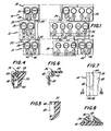
- FIGURE 4 is a cross-section of a detail of Fig. 2 as seen at the plane IV--IV in Fig. 2, drawn to larger scale;
- FIGURES 5 and 6 are cross-sections of the components of Fig. 4, drawn to the same scale and viewed at the same plane;
- FIGURE 7 is a greatly enlarged detail of Fig. 2;
- FIGURE 8 is a cross-section of components shown in Fig. 7, as seen at the plane VIII--VIII of Fig. 7; and
- FIGURE 9 is a diagram of the terminals of the printed circuit board of Fig. 3.
- Figs. 1-3 represent a terminal block assembly for making wire connections to a pattern of terminals of electrical equipment represented in Fig. 9, e.g., the printed circuit board in Fig. 3. The equipment terminals can accommodate only limited misalignment (e.g. about 0.08 mm (three-thousandths of an inch)) with the terminals of the terminal block assembly.
- The illustrative terminal block assembly includes three rows of
modular terminal blocks - A typical circuit connector (Fig. 3) includes a
stationary conductor 16 having ahorizontal contact portion 16a, a downward projecting pin terminal 16b and a resilient detent 16c.Contact portion 16a extends between the top and bottom walls and between the side walls of a four-wall clamp 18.Screw 20 extends through the threaded double-thick top wall ofclamp 18. The lower end ofscrew 20 bears against the top ofcontact portion 16a. As the screw is tightened, it draws the bottom wall or jaw ofclamp 18 upward, so that an inserted wire is gripped between the clamp's jaw andcontact portion 16a. This form of screw-operated clamp and stationary contact constitutes an excellent, well-known form of wire gripper. - Each
terminal block 22 ofrow 10 includes twoconnectors insulation 24 except for projecting pin terminal 16b. Detent 16c is received in ahole 24a in the insulating body, holdingconductor 16 in place. A wire (not shown) enters the connector via an opening 24b. - Rows of
terminal blocks row 22 are successively taller thanterminal blocks 22.Terminal blocks terminal block 22, except for their different heights. The parts of all the terminal blocks that are identical bear the same numerals, while corresponding parts that are different bear the same numerals, distinguished by (′) and (˝). Becauseterminal blocks 26 ofrow 12 are taller thanblocks 22 ofrow 10, circuit wires can extend overterminal blocks 22 for insertion into respective openings 24b ofterminal blocks 26. Each inserted wire is gripped by screw-operatedclamp 18 andcontact portion 16a of a connector inblock 26. Eachconductor 16′ inblocks 26 is elongated, to reach its projecting pin terminal 16b′. - Correspondingly,
terminal blocks 28 ofrow 14 have openings 24b at the left (Fig. 3) so that wires can extend overterminal blocks 26 and intoterminal blocks 28, to be gripped byparts 16˝ and 18 of those terminal blocks.Conductors 16˝ ofterminal blocks 28 are long enough to reach pin terminals 16b˝ that project downward from the common bottom plane of all three rows of terminal blocks. - As seen in Fig. 1,
terminal block 26 at the left end ofrow 12 is offset in relation to theterminal block 22 at the left end ofrow 10. All of the other terminal blocks of these two rows are offset correspondingly. The connectors contained in theterminal blocks 26 ofrow 12 are correspondingly offset from the two connectors in theterminal blocks 22 ofrow 10. One benefit of this offset relationship is that wiring is made easier. Wires enteringterminal blocks 26 do not obstruct access toscrews 20 of the connectors ofterminal blocks 22.Terminal blocks 26 ofrow 12 are also offset relative toterminal blocks 28 ofrow 14, with the resulting ease of wiring. Wires entering anyterminal block 28 do not obstruct access toscrews 20 ofterminal blocks 26. While wires enteringterminal blocks 28 may extend overscrews 20 ofterminal blocks 22,blocks 28 are so much taller thanblocks 22 that access to the screws of theshorter blocks 22 is not difficult. - The left-
hand terminal blocks hand terminal blocks dovetail joint 30. These dovetail joints constitute formations that unify the terminal blocks of the threerows - If an assembly of only two rows of terminal blocks is needed,
row 14 can be omitted.Blocks row 12 could be omitted, and in that event, the terminal blocks 28 would be aligned withterminal blocks 22 and unified in pairs by their dovetail joints 30. - The terminal blocks of each row are movable toward and away from each other to a limited extent, and the groups of three unified terminal blocks 22, 26 and 28 (as well as unified pairs) are correspondingly movable toward and away from each other to a limited extent. This controlled limited movement results from interlocking
formations 32 ofblocks formations 34 of terminal blocks 26 and 28. Each of these interlocking formations involves what may be called a spline on one block that is received in a generally complementary groove in the other. The dimensions of the spline are narrower than the corresponding dimensions of the groove, in the direction parallel to the lengths of the rows. For this reason, each block of each row, and each group of unified blocks, is movable toward and away from its neighboring or next-adjacent block(s) or group(s). (The end blocks of each row, of course, have only one next-adjacent block and they are movable toward and away from only one next-adjacent block; hence the terms "block(s)" and "group(s)" are useful.) - These interlocking formations that allow limited lengthening and contraction of each row of terminal blocks, as well as lengthening and contraction of all the rows of blocks, might be simple ribs that only limit such lengthening and contraction. In this example, their cross-section is T-shaped. The wide portion of the groove in one block that receives the cross-bar of the "T" is wider (horizontally, Fig. 1) than the length of the cross-bar, and the slot of that groove which receives the center bar of the "T" is wider than that center bar. Accordingly, the T-shaped formations allow limited movement -- e.g. 0.012 inch -- of each terminal block relative to its neighbor(s). However, the top cross-bar of the "T" has a snug sliding fit (horizontal in Fig. 1) in its receiving portion of the groove formation. Therefore, those interlocking T-shaped formations not only allow each row of terminal blocks to lengthen and contract, but they complement
joints 30 in holding each row of terminal blocks in assembly to its adjacent row(s) of terminal blocks. To like effect, the T-shaped interlocking formations may be L-shaped. - The left-hand
end terminal block 28 inrow 12 has an interlockingformation 34 retaining it assembled to the second-from-leftterminal block 26 ofrow 12 due to the offset relationship of the terminal blocks 26 relative to blocks 28. In the same way, interlockingformations 32 are formed between the left-handend terminal block 22 ofrow 10 and the second-from-leftterminal block 26 ofrow 12, due to their offset relationship. These interlockingformations unified blocks row 14 of terminal blocks 22 or blocks 28 is omitted, the described interlockingformations - Figs. 1-4 show three
members 36 that have two basicallyflat webs web 38 rests on the top of a respective row of terminal blocks 22, 26 or 28 and theother web 40 abuts the front face of that row of terminal blocks. (See Figs. 7 and 8.) - Each "top"
web 38 has a vertical (Figs. 6 and 7) hook ordetent 42 that is thick at its top end where it extends fromweb 38, and it is thin at its opposite, lower hooked end. Each terminal block has aslot 44 extending downward from its top and along its front. There is a deformable web 46 (Fig. 5) extending acrossslot 44 from one side to the other. Thisweb 46 is for example an integral portion of the insulating body of each terminal block, respectively (e.g., body 24).Web 46 is tough, deformable and resilient, being part ofbody 24 as of nylon.Member 36 hasmultiple hooks 42 distributed along its length, located to be received inslots 44 of the terminal blocks.Member 36 is of a relatively rigid dimensionally stable molded plastic, for example polyethylene terephthalate. When hooks 42 are forced into the spaces behindwebs 46,member 36 becomes locked to a row of terminal blocks, withtop web 38 against the tops of a respective row of terminal blocks. - The
front web 40 ofmember 36 has a series of ribs 48 (Fig. 8) that are snugly received ingrooves 44 of respective terminal blocks.Ribs 48 are aligned withhooks 42. Hoods 42 (like ribs 48) fit snugly across the width ofslots 44. Both thehooks 42 and theribs 48 of each elongated member fix the terminal blocks of a row against relative movement along the row. - Two differently dimensioned forms of
member 36 are provided. In one form, hooks 42 andribs 48 are at spaced intervals that fix the terminal blocks of a row close together, while in another form ofmember 36, hooks 42 andribs 48 fix the terminal blocks of a row in precise spaced-apart relationship. The blocks of a row are close together when a desired minimum spacing is established between their row of pin terminals 16b, 16b′ or 16b˝. Blocks that are close may abut one another but it is advantageous to allow some space between them. (If the blocks were designed to be in abutment, the row of blocks in practice could be over-size due to manufacturing variations and the effects of changing temperature and humidity.) Each form ofmember 36 correspondingly determines the distribution of each row of pin terminals 16b, 16b′ or 16b˝. One form ofmember 36 fixes terminals 16b, 16b′ and 16b˝ at millimeter-based positions. Another form ofmember 36 has itshooks 42 andribs 48 spaced apart at modular inch-based positions that fix pin terminals 16b, 16b′ and 16b˝ correspondingly. The length of eachmember 36 is cut to conform to the desired length of the row of terminal blocks to which it is assembled. In this way, each row of pin terminals 16b, as well as pin terminals 16b′ and 16b˝ are spaced apart for direct cooperation with a respective row of apertures that constitute terminals 50, 50′ and 50˝ of theelectrical equipment 52, whether its design is inch-based or millimeter-based. The electrical equipment here in (or comprises) a printedcircuit board 52 for example. The pattern of pin terminals 16b, 16b′ and 16b˝ is established bymembers 36 before the assembled terminal blocks are mounted on the printed circuit board. - Considering Fig. 3, the row-to-row separation of pin terminals 16b, 16b′ and 16b˝ will be somewhat different when designed pursuant to inch-based standards or millimeter-based standards. The elongated conductors bearing pin terminals 16b′ and 16b˝ are amply flexible and they are movable to some extent toward and away from pin terminals 16b, to be deflected (as may be needed) for alignment with the respective rows of the equipment terminals.
- Figs. 1-3 are drawn to scale, substantially enlarged, and Figs. 4-6 are similarly drawn to a different enlarged scale. The width of each
terminal block member 36 corresponding to the inch-based or millimeter-based modular terminal distribution of the electrical equipment. - It is evident that the assembly of terminal blocks may be reduced to a single row. In that event, the T-shaped (or L-shaped) interlocking
formations 32 are to be interposed (for example) between eachblock 22 and the next. The shapes of the splines and the grooves are modified, of course, to accommodate limited movement ofblocks 22 toward and away from each other while maintaining the front and back surfaces of those blocks in alignment. - The illustrative embodiment of the invention described above and shown in the accompanying drawings, may be modified and variously applied to meet various circumstances, so that the appended claims should be construed broadly, in accordance with the spirit of the invention.
Claims (24)
Applications Claiming Priority (2)
| Application Number | Priority Date | Filing Date | Title |
|---|---|---|---|
| US07/202,801 US4872855A (en) | 1988-06-03 | 1988-06-03 | Adjustable terminal block equipment |
| US202801 | 2008-09-02 |
Publications (2)
| Publication Number | Publication Date |
|---|---|
| EP0345095A2 true EP0345095A2 (en) | 1989-12-06 |
| EP0345095A3 EP0345095A3 (en) | 1990-08-29 |
Family
ID=22751336
Family Applications (1)
| Application Number | Title | Priority Date | Filing Date |
|---|---|---|---|
| EP89305614A Withdrawn EP0345095A3 (en) | 1988-06-03 | 1989-06-02 | Adjustable terminal block equipment |
Country Status (2)
| Country | Link |
|---|---|
| US (1) | US4872855A (en) |
| EP (1) | EP0345095A3 (en) |
Cited By (1)
| Publication number | Priority date | Publication date | Assignee | Title |
|---|---|---|---|---|
| DE29917491U1 (en) * | 1999-10-05 | 2001-03-22 | Weidmüller Interface GmbH & Co., 32758 Detmold | Terminal block |
Families Citing this family (12)
| Publication number | Priority date | Publication date | Assignee | Title |
|---|---|---|---|---|
| JPH077040B2 (en) * | 1992-12-07 | 1995-01-30 | 山一電機株式会社 | Socket for electrical parts |
| US5740004A (en) * | 1995-09-14 | 1998-04-14 | Lucent Technologies Inc. | Small pair connector building entrance protector |
| JP3320986B2 (en) * | 1996-08-27 | 2002-09-03 | 矢崎総業株式会社 | Coupling connector |
| US5999394A (en) * | 1998-06-05 | 1999-12-07 | General Electric Company | Terminal block for a protective relay |
| US6456479B1 (en) * | 2000-02-18 | 2002-09-24 | General Electric Company | Keycode connection arrangement between a processing module and a terminal block |
| US6589071B1 (en) * | 2002-02-04 | 2003-07-08 | Eaton Corporation | Circuit breaker jumper assembly with a snap-fit cover assembly |
| US6491544B1 (en) * | 2002-02-04 | 2002-12-10 | Eaton Corporation | Multi-unit circuit breaker jumper assembly |
| FR2841377B1 (en) * | 2002-06-25 | 2004-08-06 | Schneider Electric Ind Sa | ELECTROMAGNETIC PROTECTION AND CONTROL ASSEMBLY |
| CN100474698C (en) * | 2003-05-28 | 2009-04-01 | 西门子能量及自动化公司 | Connectors and methods for connecting wires |
| EP3695471B1 (en) * | 2017-10-09 | 2022-03-16 | BAE Systems PLC | Plug assembly |
| US10194553B1 (en) * | 2017-11-11 | 2019-01-29 | Rockwell Automation Asia Pacific Business Center Pte. Ltd. | Selectively installable and removable auxiliary wiring device for I/O module |
| US11955759B2 (en) * | 2021-01-13 | 2024-04-09 | Rain Bird Corporation | Irrigation controller with vertically offset terminal connectors rows |
Family Cites Families (5)
| Publication number | Priority date | Publication date | Assignee | Title |
|---|---|---|---|---|
| US3259876A (en) * | 1963-09-11 | 1966-07-05 | Alexander R Norden | Electrical terminal blocks and mounting rails |
| DE2716700A1 (en) * | 1977-04-15 | 1978-10-19 | Wago Kontakttechnik Gmbh | Screwless connecting clamp with adjacent insulating housings - has lids of each housing coupled by flexible strips |
| DE3014755A1 (en) * | 1980-04-17 | 1981-10-22 | C.A. Weidmüller KG, 4930 Detmold | MIXABLE BLOCK FOR ELECTRICAL CONNECTORS |
| US4343528A (en) * | 1980-04-25 | 1982-08-10 | Amp Incorporated | Modular interconnect system |
| US4381133A (en) * | 1981-04-02 | 1983-04-26 | Cooper Industries, Inc. | Variable center distance terminal strip and method of making same |
-
1988
- 1988-06-03 US US07/202,801 patent/US4872855A/en not_active Expired - Fee Related
-
1989
- 1989-06-02 EP EP89305614A patent/EP0345095A3/en not_active Withdrawn
Cited By (1)
| Publication number | Priority date | Publication date | Assignee | Title |
|---|---|---|---|---|
| DE29917491U1 (en) * | 1999-10-05 | 2001-03-22 | Weidmüller Interface GmbH & Co., 32758 Detmold | Terminal block |
Also Published As
| Publication number | Publication date |
|---|---|
| EP0345095A3 (en) | 1990-08-29 |
| US4872855A (en) | 1989-10-10 |
Similar Documents
| Publication | Publication Date | Title |
|---|---|---|
| US6645003B2 (en) | Joint connector | |
| EP0482669B1 (en) | Electrical connector and method of making an electrical connector | |
| US4872855A (en) | Adjustable terminal block equipment | |
| US4322120A (en) | Plug-in connector with improved spring contact | |
| EP0627789B1 (en) | Connector assembly for printed circuit boards | |
| US4550962A (en) | Solderless electrical connector assembly | |
| CA1108280A (en) | Frame unit for electronic communication devices | |
| US6241561B1 (en) | Terminal block arrangement for an electrical system | |
| US3448345A (en) | Interconnection system | |
| US4439000A (en) | Surface mount/daughter board connector | |
| EP0838101B1 (en) | Electrical connectors | |
| US3372308A (en) | Interconnecting frame assembly with improved connector structure | |
| CA1216038A (en) | Multiple electrical connector and block with printed circuit board connector clip | |
| CA1101977A (en) | Modular housing means for electrical and electronic components | |
| IE45134B1 (en) | Improvements in or relating to sectioning tap blocks for telecommunication systems | |
| US4398779A (en) | Keying apparatus for interconnecting electrical components | |
| US4717344A (en) | Connector for circuit boards | |
| US6325659B1 (en) | Electrical connector for solderless connection to edge card connector, and dual connector-printed circuit board assembly | |
| CA2269963A1 (en) | High density high performance telecommunications/data link and connector with tap and contact displacement assembly | |
| US5790660A (en) | Shunted modular jack | |
| EP0643449B1 (en) | Cable connector for a ribbon cable | |
| EP0639873B1 (en) | Connector | |
| US4671601A (en) | Connector for individual conductors | |
| US5013250A (en) | Multi-pole connector plug | |
| US4871326A (en) | Electrical harness having one connector intended for circuit board mounting |
Legal Events
| Date | Code | Title | Description |
|---|---|---|---|
| PUAI | Public reference made under article 153(3) epc to a published international application that has entered the european phase |
Free format text: ORIGINAL CODE: 0009012 |
|
| AK | Designated contracting states |
Kind code of ref document: A2 Designated state(s): DE FR GB IT |
|
| RIN1 | Information on inventor provided before grant (corrected) |
Inventor name: NORDEN, ALEXANDER |
|
| PUAL | Search report despatched |
Free format text: ORIGINAL CODE: 0009013 |
|
| AK | Designated contracting states |
Kind code of ref document: A3 Designated state(s): DE FR GB IT |
|
| RHK1 | Main classification (correction) |
Ipc: H01R 9/24 |
|
| 17P | Request for examination filed |
Effective date: 19901220 |
|
| STAA | Information on the status of an ep patent application or granted ep patent |
Free format text: STATUS: THE APPLICATION HAS BEEN WITHDRAWN |
|
| 18W | Application withdrawn |
Withdrawal date: 19930622 |