EP0345072A2 - Folding legged furniture - Google Patents
Folding legged furniture Download PDFInfo
- Publication number
- EP0345072A2 EP0345072A2 EP89305562A EP89305562A EP0345072A2 EP 0345072 A2 EP0345072 A2 EP 0345072A2 EP 89305562 A EP89305562 A EP 89305562A EP 89305562 A EP89305562 A EP 89305562A EP 0345072 A2 EP0345072 A2 EP 0345072A2
- Authority
- EP
- European Patent Office
- Prior art keywords
- legs
- pair
- item
- plane
- side walls
- Prior art date
- Legal status (The legal status is an assumption and is not a legal conclusion. Google has not performed a legal analysis and makes no representation as to the accuracy of the status listed.)
- Withdrawn
Links
Images


Classifications
-
- B—PERFORMING OPERATIONS; TRANSPORTING
- B25—HAND TOOLS; PORTABLE POWER-DRIVEN TOOLS; MANIPULATORS
- B25H—WORKSHOP EQUIPMENT, e.g. FOR MARKING-OUT WORK; STORAGE MEANS FOR WORKSHOPS
- B25H1/00—Work benches; Portable stands or supports for positioning portable tools or work to be operated on thereby
- B25H1/06—Work benches; Portable stands or supports for positioning portable tools or work to be operated on thereby of trestle type
-
- A—HUMAN NECESSITIES
- A47—FURNITURE; DOMESTIC ARTICLES OR APPLIANCES; COFFEE MILLS; SPICE MILLS; SUCTION CLEANERS IN GENERAL
- A47B—TABLES; DESKS; OFFICE FURNITURE; CABINETS; DRAWERS; GENERAL DETAILS OF FURNITURE
- A47B3/00—Folding or stowable tables
- A47B3/08—Folding or stowable tables with legs pivoted to top or underframe
- A47B3/0818—Folding or stowable tables with legs pivoted to top or underframe with manually actuated locking means
-
- A—HUMAN NECESSITIES
- A47—FURNITURE; DOMESTIC ARTICLES OR APPLIANCES; COFFEE MILLS; SPICE MILLS; SUCTION CLEANERS IN GENERAL
- A47B—TABLES; DESKS; OFFICE FURNITURE; CABINETS; DRAWERS; GENERAL DETAILS OF FURNITURE
- A47B3/00—Folding or stowable tables
- A47B3/08—Folding or stowable tables with legs pivoted to top or underframe
- A47B2003/0821—Folding or stowable tables with legs pivoted to top or underframe the leg holder being mounted to underside of the table top
Definitions
- This invention relates to folding-legged furniture, and particularly, but not exclusively to items of furniture such as trestles, tables, work benches,saw horses and the like, in which the legs are foldable between an extended supporting position and a stowed position.
- Sawhorses, trestles and the like are used by carpenters and other radesmen to support timber and other construction materials, and for supporting platforms and the like. It is conventional for sawhorses to have legs which splay out laterally, in order to provide stability; it is difficult to reconcile the requirement for the legs to splay out with the desirability for the sawhorse to be foldable so that it is easy to transport and store.
- an item of folding-legged furniture including a top, to the underside of which a first pair of legs and a second pair of legs are each mounted on pivots in respective inverted channel-section brackets having substantially parallel opposed side walls which are inclined outwardly, the axes of the pivots being relatively inclined and movable along slots provided in said opposed side walls such that the legs may be pivotted between an extended, supporting position in which the legs are relatively laterally splayed, and a stowed position in which one leg of each pair overlies a corresponding one of the other pair.
- the axes of the first pair of legs lie substantially in a first plane in the stowed position while the axes of the second pair of legs lie substantially in a second plane spaced from the first plane.
- the axis of one of the first pair of legs and of the diagonally opposite leg of the second pair may lie substantially in a first plane in the stowed position, while the axis of the other of the first pair of legs and that of the remaining leg lie substantially in a second plane spaced from the first plane.
- the axes of all the legs should be substantially parallel to one another in the stowed position, the axes being generally parallel to the long dimension of the top and to the upper surface of the top.
- the top is typically long and narrow, such as a long and narrow rectangle.
- the side walls of the inverted channel-section bracket are preferably inclined relative to a cross-member or web joining the side walls.
- the brackets are generally mounted to the underside of the top in such a way that they are symmetrically disposed on the underside, relative to the longitudinal axis thereof (and preferably also relative to the transverse axis thereof).
- the side walls are preferably such that in each bracket, opposed side walls are contiguous with the respective leg both when the legs are in the stowed position and when they are in the extended position.
- the legs are preferably mounted in such brackets such that the pivot axis is normal to the planes of the side walls.
- the pivot is preferably a pin extending through the respective leg, normal to the long axis thereof and through the slot provided in each side wall.
- the top preferably includes an abutment against which each pair of legs bears when in the extended position.
- abutments may be so located that when the legs are in the extended position they are splayed within the plane in which the legs lie, the latter plane being inclined outwardly away from the plane of the top.
- Locking means may be provided to hold the legs against the abutments, and retained means may be provided to hold the legs in the stowed position.
- an item of furniture in the form of a trestle has a flat elongate top 10, typically made of wood, sheet metal or plastics, to the underside of which is secured a folded sheet metal frame 11. Near each end of the top 10, two strong brackets 12 are fastened to the underside of the frame 11.
- the brackets 12 are of inverted channel-section, having parallel side walls 13 and a connecting web 14 inclined relative to the side walls 13.
- the top 10 and the frame 11 are supported on four identical square-section tubular metal legs 15.
- the spacing between the side walls 13 of each bracket 12 allows one leg 15 to be received and to slide and pivot while remaining contiguous with the side walls 13 (without undue play).
- the angle between each outwardly inclined side wall 13 and the connecting web 14 determines the angle of splay of the legs 15.
- a pivot pin 16 fits in a transverse bore through the leg 15, near the square-cut upper end 15a thereof.
- the pivot pin 16 also passes through parallel slots 17 in each side wall 13 of the bracket 12.
- the slots 17 enable the leg 15 to move away from the top 10, as the leg 15 is pivotted, so that the upper end 15a of the respective leg 15 can clear the underside of the base member 14.
- pair of legs 15 at one end are, in their supporting extended position, located by a T-shaped bar 19 against a transverse bar 18, fastened to the frame 11.
- the centre member of the bar 19 is threaded, carries a collar 20 and extends through the bar 18.
- the legs 15 are swung to the extended position, with the transverse member of the T-shaped bar 19 in the vertical position.
- the bar 19 is rotated through 90° and the transverse member tightened against the back of the legs 15 by a wing nut 21 on the threaded central member of the bar 19.
- the pivot pins 16 are transverse to the length of the frame 11, and at an acute angle to a line leading from a central line along the underside of the top 10, to the lateral edge thereof; the legs 15 can therefore be swung upwards to stowed positions which are wholly within the frame 11.
- the axes of the legs 15 are then substantially parallel, with the legs from one end overlying the legs from the other end, as seen in Figure 6. They are located in a bracket 22, positioned centrally along the length of of the frame 11, and (in the embodiment illustrated in Figure 6) are retained by a bar 23, pulled upwards by a spring 24. The upper end of the spring 24 is received in a central member 25.
- the legs 15 are released by pulling the bar 23 downwards and turning it clear of the legs 15 (see Figure 5).
- the legs 15 need not be metal, but could be of wood and non-tubular and of any suitable cross-section provided the upper side faces within the bracket 12 are flat and parallel.
- ground-engaging legs of the item of furniture according to the invention may be mitred in such a way that when the they are in the extended position, they are substantially flush with the ground.
- the ends may have squared-off ends to which are secured ground-engaging feet which are shaped to lie substantially flush with the ground when the legs are in the extended position.
- bracket 22 comprises a pair of channel members 26 each capable of receiving one from each end pair of legs 15, one overlying the other as shown.
- the channel members 26 are each inclined relative to the underside 9 of the top 10 at an angle corresponding to that of the side walls 13 of bracket 12.
- each channel member At the free end of the inner wall 27 of each channel member is an inwardly projecting lug 28; this lug has a tapered lower face 29 such that the legs 15 may be pressed past the lug, but when two legs are present in channel member 26 they are retained by the resilient action of inner wall 27 in combination with lug 28.
- the lug further has a tapered upper face 30 such that the legs can be readily pushed past the lug and out of the channel member.
Landscapes
- Engineering & Computer Science (AREA)
- Mechanical Engineering (AREA)
- Furniture Connections (AREA)
- Tables And Desks Characterized By Structural Shape (AREA)
Abstract
The item of furniture, typically a craftsman's trestle, includes a generally rectangular top (10) having four legs (15) pivotally mounted in inverted channel-section brackets (12) with opposed side walls (13), the pivots (16) being relatively inclined and movable along slots (17) in the opposed side walls, such that the legs can be pivotted between an extended, supporting position in which the legs are relatively splayed, and a stowed position in which the leg of each pair overlies a corresponding one of the other pair.
Description
- This invention relates to folding-legged furniture, and particularly, but not exclusively to items of furniture such as trestles, tables, work benches,saw horses and the like, in which the legs are foldable between an extended supporting position and a stowed position.
- Sawhorses, trestles and the like are used by carpenters and other radesmen to support timber and other construction materials, and for supporting platforms and the like. It is conventional for sawhorses to have legs which splay out laterally, in order to provide stability; it is difficult to reconcile the requirement for the legs to splay out with the desirability for the sawhorse to be foldable so that it is easy to transport and store.
- We have now devised an item of folding-legged furniture which can be folded into compact, transportable form while still being strong and sturdy when the legs are in their supporting positions.
- According to the present invention there is provided an item of folding-legged furniture including a top, to the underside of which a first pair of legs and a second pair of legs are each mounted on pivots in respective inverted channel-section brackets having substantially parallel opposed side walls which are inclined outwardly, the axes of the pivots being relatively inclined and movable along slots provided in said opposed side walls such that the legs may be pivotted between an extended, supporting position in which the legs are relatively laterally splayed, and a stowed position in which one leg of each pair overlies a corresponding one of the other pair.
- In one embodiment of the invention, the axes of the first pair of legs lie substantially in a first plane in the stowed position while the axes of the second pair of legs lie substantially in a second plane spaced from the first plane. Alternatively, the axis of one of the first pair of legs and of the diagonally opposite leg of the second pair may lie substantially in a first plane in the stowed position, while the axis of the other of the first pair of legs and that of the remaining leg lie substantially in a second plane spaced from the first plane.
- It is preferred that the axes of all the legs should be substantially parallel to one another in the stowed position, the axes being generally parallel to the long dimension of the top and to the upper surface of the top. The top is typically long and narrow, such as a long and narrow rectangle.
- The side walls of the inverted channel-section bracket are preferably inclined relative to a cross-member or web joining the side walls. The brackets are generally mounted to the underside of the top in such a way that they are symmetrically disposed on the underside, relative to the longitudinal axis thereof (and preferably also relative to the transverse axis thereof). The side walls are preferably such that in each bracket, opposed side walls are contiguous with the respective leg both when the legs are in the stowed position and when they are in the extended position.
- The legs are preferably mounted in such brackets such that the pivot axis is normal to the planes of the side walls. The pivot is preferably a pin extending through the respective leg, normal to the long axis thereof and through the slot provided in each side wall.
- The top preferably includes an abutment against which each pair of legs bears when in the extended position. Such abutments may be so located that when the legs are in the extended position they are splayed within the plane in which the legs lie, the latter plane being inclined outwardly away from the plane of the top. Locking means may be provided to hold the legs against the abutments, and retained means may be provided to hold the legs in the stowed position.
- Preferred embodiments of the invention, as applied to a trestle, will now be described, by way of example only, with reference to the accompanying drawings, in which:-
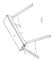
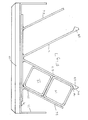
- Figure 1 is a perspective view of a trestle, according to the invention;
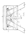
- Figure 2 is an end elevation, at enlarged scale, of the trestle shown in Figure 1;
- Figure 3 is a side elevation of the trestle of Figure 1;
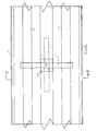
- Figure 4 is an upwards view of one end of the trestle shown in Figure 1;
- Figure 5 is an upwards view of the centre of the trestle shown in Figure 1;
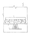
- Figure 6 is a section along line -
 in Figure 5; and
- Figure 7 shows, in sectional view, an alternative to the arrangement of Figure 6.
- In the drawings, an item of furniture in the form of a trestle, has a flat
elongate top 10, typically made of wood, sheet metal or plastics, to the underside of which is secured a foldedsheet metal frame 11. Near each end of thetop 10, twostrong brackets 12 are fastened to the underside of theframe 11. Thebrackets 12 are of inverted channel-section, havingparallel side walls 13 and a connectingweb 14 inclined relative to theside walls 13. - The
top 10 and theframe 11 are supported on four identical square-sectiontubular metal legs 15. The spacing between theside walls 13 of eachbracket 12 allows oneleg 15 to be received and to slide and pivot while remaining contiguous with the side walls 13 (without undue play). Thus the angle between each outwardlyinclined side wall 13 and the connectingweb 14 determines the angle of splay of thelegs 15. - A pivot pin 16 fits in a transverse bore through the
leg 15, near the square-cut upper end 15a thereof. The pivot pin 16 also passes throughparallel slots 17 in eachside wall 13 of thebracket 12. Theslots 17 enable theleg 15 to move away from thetop 10, as theleg 15 is pivotted, so that the upper end 15a of therespective leg 15 can clear the underside of thebase member 14. - Not only are the
legs 15 splayed in the end view, as seen in Figure 2, but also in the side view, as seen in Figure 3. As shown in Figures 2 to 5, pair oflegs 15 at one end are, in their supporting extended position, located by a T-shaped bar 19 against atransverse bar 18, fastened to theframe 11. The centre member of thebar 19 is threaded, carries acollar 20 and extends through thebar 18. Thelegs 15 are swung to the extended position, with the transverse member of the T-shaped bar 19 in the vertical position. Thebar 19 is rotated through 90° and the transverse member tightened against the back of thelegs 15 by awing nut 21 on the threaded central member of thebar 19. - The pivot pins 16 are transverse to the length of the
frame 11, and at an acute angle to a line leading from a central line along the underside of thetop 10, to the lateral edge thereof; thelegs 15 can therefore be swung upwards to stowed positions which are wholly within theframe 11. The axes of thelegs 15 are then substantially parallel, with the legs from one end overlying the legs from the other end, as seen in Figure 6. They are located in abracket 22, positioned centrally along the length of of theframe 11, and (in the embodiment illustrated in Figure 6) are retained by abar 23, pulled upwards by aspring 24. The upper end of thespring 24 is received in acentral member 25. Thelegs 15 are released by pulling thebar 23 downwards and turning it clear of the legs 15 (see Figure 5). - When the
legs 15 are stowed, the wing nut 21 (see Figures 2 to 4) is tightened until thecollar 20 bears against thebar 18, to hold the T-shaped bar 19 within theframe 11. - The
legs 15 need not be metal, but could be of wood and non-tubular and of any suitable cross-section provided the upper side faces within thebracket 12 are flat and parallel. - The ground-engaging legs of the item of furniture according to the invention may be mitred in such a way that when the they are in the extended position, they are substantially flush with the ground. Alternatively, the ends may have squared-off ends to which are secured ground-engaging feet which are shaped to lie substantially flush with the ground when the legs are in the extended position.
- Referring to Figure 7 (in which like parts to those of Figure 6 are denoted by like reference numerals),
bracket 22 comprises a pair ofchannel members 26 each capable of receiving one from each end pair oflegs 15, one overlying the other as shown. Thechannel members 26 are each inclined relative to the underside 9 of thetop 10 at an angle corresponding to that of theside walls 13 ofbracket 12. - At the free end of the
inner wall 27 of each channel member is an inwardly projectinglug 28; this lug has a taperedlower face 29 such that thelegs 15 may be pressed past the lug, but when two legs are present inchannel member 26 they are retained by the resilient action ofinner wall 27 in combination withlug 28. The lug further has a taperedupper face 30 such that the legs can be readily pushed past the lug and out of the channel member.
Claims (10)
1. An item of folding-legged furniture including a top, to the underside of which a first pair of legs and a second pair of legs are each mounted on pivots in a respectively inverted channel-section bracket having substantially parallel opposed side walls which are inclined outwardly, the axes of the pivots being relatively inclined and movable along slots provided in said opposed side walls such that the legs may be pivotted between an extended, supporting position in which the legs are relatively laterally splayed, and a stowed position in which one leg of each pair overlies a corresponding one of the other pair.
2. An item of furniture according to claim 1, wherein in the stowed position the axes of the first pair of legs lie substantially in a first plane and the axes of the second pair of legs lie substantially in a second plane spaced from the first plane; or wherein the axis of one of the first pair of legs and of the diagonally opposite leg of the second pair lie substantially in a first plane in the stowed position, while the axis of the other of the first pair of legs and that of the remaining leg lie substantially in a second plane spaced from the first plane.
3. An item of furniture according to claim 1 or 2, wherein the axes of all the legs are substantially parallel to one another in the stowed position, said axes being parallel to the upper surface of the top.
4. An item of furniture according to any of claims 1 to 3, wherein said opposed side walls are inclined outwardly relative to a cross-member or web joining said side walls.
5. An item of furniture according to any of claims 1 to 4, wherein said brackets are mounted to said underside in an array which is symmetrical relative to the longitudinal axis of said underside.
6. An item of furniture according to any of claims 1 to 5, wherein said side walls are such that they are contiguous with the respective legs both when said legs are in the stowed position and when they are in the extended position.
7. An item of furniture according to any of claims 1 to 6, wherein said legs are mounted in said brackets in such a way that the respective pivot axes thereof are normal to the planes of the respective side walls.
8. An item of furniture according to any of claims 1 to 7, wherein each said pivotal mounting comprises a pin extending through the respective leg, normal to the axis thereof, and through the slot in each respective side wall.
9. An item of furniture according to any of claims 1 to 8, wherein said top includes an abutment against which each pair of legs bears when in the extended position, said abutments being located such that when the legs are in the extended position they are splayed within the plane in which the legs lie, the latter plane being inclined outwardly away from the plane of the top.
10. An item of furniture according to any of claims 1 to 9, which further comprises locking means arranged to hold said legs against said abutments and/or retaining means arranged to hold said legs in the stowed position.
Applications Claiming Priority (2)
| Application Number | Priority Date | Filing Date | Title |
|---|---|---|---|
| GB8813022 | 1988-06-02 | ||
| GB888813022A GB8813022D0 (en) | 1988-06-02 | 1988-06-02 | Folding-legged furniture |
Publications (2)
| Publication Number | Publication Date |
|---|---|
| EP0345072A2 true EP0345072A2 (en) | 1989-12-06 |
| EP0345072A3 EP0345072A3 (en) | 1990-10-03 |
Family
ID=10637925
Family Applications (1)
| Application Number | Title | Priority Date | Filing Date |
|---|---|---|---|
| EP19890305562 Withdrawn EP0345072A3 (en) | 1988-06-02 | 1989-06-02 | Folding legged furniture |
Country Status (2)
| Country | Link |
|---|---|
| EP (1) | EP0345072A3 (en) |
| GB (2) | GB8813022D0 (en) |
Cited By (2)
| Publication number | Priority date | Publication date | Assignee | Title |
|---|---|---|---|---|
| GB2288970A (en) * | 1994-04-12 | 1995-11-08 | Brian Alfred Albert | Trestle bracket |
| US10993528B1 (en) | 2020-07-30 | 2021-05-04 | Leetes Island Woodworks, LLC | Sawhorse table |
Family Cites Families (9)
| Publication number | Priority date | Publication date | Assignee | Title |
|---|---|---|---|---|
| US2664319A (en) * | 1949-01-29 | 1953-12-29 | Edmund J Doucette | Collapsible sawhorse or trestle |
| US3198286A (en) * | 1962-12-03 | 1965-08-03 | Homer M Wilson | Folding sawhorse |
| US3269487A (en) * | 1964-11-09 | 1966-08-30 | Larson Co Charles O | Saw horse structure |
| CH421862A (en) * | 1965-03-26 | 1966-09-30 | Mueller Wilhelm | Collapsible work trestle |
| DE2309576A1 (en) * | 1973-02-26 | 1974-09-05 | Guenther Dipl-Ing Rogge | FOLDING JOINT WITH SLIDING AXLE |
| US3951233A (en) * | 1975-09-22 | 1976-04-20 | Daniel Meyers | Collapsible sawhorse |
| EP0130200A1 (en) * | 1982-12-24 | 1985-01-09 | Ensat Pty. Ltd. | Folding leg bracket |
| DE8528600U1 (en) * | 1985-10-08 | 1986-02-06 | Hoffmann, Peter, 5860 Iserlohn | Folding table frame with legs guided by running rails and foldable |
| US4645162A (en) * | 1986-02-25 | 1987-02-24 | Bertrand Roy | Leg support structure |
-
1988
- 1988-06-02 GB GB888813022A patent/GB8813022D0/en active Pending
-
1989
- 1989-06-02 EP EP19890305562 patent/EP0345072A3/en not_active Withdrawn
- 1989-06-02 GB GB8912687A patent/GB2219200B/en not_active Expired - Lifetime
Cited By (4)
| Publication number | Priority date | Publication date | Assignee | Title |
|---|---|---|---|---|
| GB2288970A (en) * | 1994-04-12 | 1995-11-08 | Brian Alfred Albert | Trestle bracket |
| GB2288970B (en) * | 1994-04-12 | 1998-04-08 | Brian Alfred Albert | Trestle bracket |
| US10993528B1 (en) | 2020-07-30 | 2021-05-04 | Leetes Island Woodworks, LLC | Sawhorse table |
| US11330901B2 (en) | 2020-07-30 | 2022-05-17 | Leetes Island Woodworks, LLC | Sawhorse support and table |
Also Published As
| Publication number | Publication date |
|---|---|
| GB2219200B (en) | 1991-10-23 |
| GB2219200A (en) | 1989-12-06 |
| GB8813022D0 (en) | 1988-07-06 |
| EP0345072A3 (en) | 1990-10-03 |
| GB8912687D0 (en) | 1989-07-19 |
Similar Documents
| Publication | Publication Date | Title |
|---|---|---|
| US5320150A (en) | Collapsible stand | |
| US6224127B1 (en) | Modified tailgate | |
| US5954156A (en) | Adjustable saw horse | |
| US4341247A (en) | Extension table assembly for power tools | |
| US4640326A (en) | Stand for a table saw | |
| US4159821A (en) | Collapsible dual-height workbench | |
| US4645161A (en) | Support device | |
| US7240705B2 (en) | Table for portable miter saws | |
| US5383320A (en) | Tool for positioning joist hanger on header | |
| US20010047712A1 (en) | Collapsible portable saw stand | |
| CA1331392C (en) | Support bracket | |
| US5377780A (en) | Bracket assembly for saw horses | |
| US4615559A (en) | Folding table/bench combination | |
| US20070131306A1 (en) | Tool support device | |
| US4645162A (en) | Leg support structure | |
| US20110227271A1 (en) | Height-adjustable out-feed table for table saw | |
| GB2092507A (en) | Sawhorse brackets | |
| US20040124036A1 (en) | Portable work stand | |
| US6810996B2 (en) | Bracket for a sawhorse and other multiple piece stands | |
| US4298094A (en) | Collapsible sawhorse | |
| US5758744A (en) | Sawhorse | |
| US5908182A (en) | Adjustable and foldable support structure | |
| US5927436A (en) | Foldable sawhorse/worktable | |
| US5184697A (en) | Locking swivel for rotatably connecting two components | |
| US4854531A (en) | Three legged workbench |
Legal Events
| Date | Code | Title | Description |
|---|---|---|---|
| PUAI | Public reference made under article 153(3) epc to a published international application that has entered the european phase |
Free format text: ORIGINAL CODE: 0009012 |
|
| AK | Designated contracting states |
Kind code of ref document: A2 Designated state(s): AT BE CH DE ES FR GB GR IT LI LU NL SE |
|
| PUAL | Search report despatched |
Free format text: ORIGINAL CODE: 0009013 |
|
| AK | Designated contracting states |
Kind code of ref document: A3 Designated state(s): AT BE CH DE ES FR GB GR IT LI LU NL SE |
|
| STAA | Information on the status of an ep patent application or granted ep patent |
Free format text: STATUS: THE APPLICATION IS DEEMED TO BE WITHDRAWN |
|
| 18D | Application deemed to be withdrawn |
Effective date: 19910404 |