EP0345033A2 - Image forming apparatus - Google Patents
Image forming apparatus Download PDFInfo
- Publication number
- EP0345033A2 EP0345033A2 EP89305466A EP89305466A EP0345033A2 EP 0345033 A2 EP0345033 A2 EP 0345033A2 EP 89305466 A EP89305466 A EP 89305466A EP 89305466 A EP89305466 A EP 89305466A EP 0345033 A2 EP0345033 A2 EP 0345033A2
- Authority
- EP
- European Patent Office
- Prior art keywords
- photoreceptor
- original
- image
- transferring
- glass plate
- Prior art date
- Legal status (The legal status is an assumption and is not a legal conclusion. Google has not performed a legal analysis and makes no representation as to the accuracy of the status listed.)
- Granted
Links
Images


Classifications
-
- G—PHYSICS
- G03—PHOTOGRAPHY; CINEMATOGRAPHY; ANALOGOUS TECHNIQUES USING WAVES OTHER THAN OPTICAL WAVES; ELECTROGRAPHY; HOLOGRAPHY
- G03G—ELECTROGRAPHY; ELECTROPHOTOGRAPHY; MAGNETOGRAPHY
- G03G15/00—Apparatus for electrographic processes using a charge pattern
- G03G15/14—Apparatus for electrographic processes using a charge pattern for transferring a pattern to a second base
-
- G—PHYSICS
- G03—PHOTOGRAPHY; CINEMATOGRAPHY; ANALOGOUS TECHNIQUES USING WAVES OTHER THAN OPTICAL WAVES; ELECTROGRAPHY; HOLOGRAPHY
- G03G—ELECTROGRAPHY; ELECTROPHOTOGRAPHY; MAGNETOGRAPHY
- G03G15/00—Apparatus for electrographic processes using a charge pattern
- G03G15/60—Apparatus which relate to the handling of originals
- G03G15/605—Holders for originals or exposure platens
-
- G—PHYSICS
- G03—PHOTOGRAPHY; CINEMATOGRAPHY; ANALOGOUS TECHNIQUES USING WAVES OTHER THAN OPTICAL WAVES; ELECTROGRAPHY; HOLOGRAPHY
- G03G—ELECTROGRAPHY; ELECTROPHOTOGRAPHY; MAGNETOGRAPHY
- G03G15/00—Apparatus for electrographic processes using a charge pattern
- G03G15/04—Apparatus for electrographic processes using a charge pattern for exposing, i.e. imagewise exposure by optically projecting the original image on a photoconductive recording material
- G03G15/045—Apparatus for electrographic processes using a charge pattern for exposing, i.e. imagewise exposure by optically projecting the original image on a photoconductive recording material with means for charging or discharging distinct portions of the charge pattern on the recording material, e.g. for contrast enhancement or discharging non-image areas
- G03G15/047—Apparatus for electrographic processes using a charge pattern for exposing, i.e. imagewise exposure by optically projecting the original image on a photoconductive recording material with means for charging or discharging distinct portions of the charge pattern on the recording material, e.g. for contrast enhancement or discharging non-image areas for discharging non-image areas
-
- G—PHYSICS
- G03—PHOTOGRAPHY; CINEMATOGRAPHY; ANALOGOUS TECHNIQUES USING WAVES OTHER THAN OPTICAL WAVES; ELECTROGRAPHY; HOLOGRAPHY
- G03G—ELECTROGRAPHY; ELECTROPHOTOGRAPHY; MAGNETOGRAPHY
- G03G21/00—Arrangements not provided for by groups G03G13/00 - G03G19/00, e.g. cleaning, elimination of residual charge
- G03G21/06—Eliminating residual charges from a reusable imaging member
- G03G21/08—Eliminating residual charges from a reusable imaging member using optical radiation
-
- G—PHYSICS
- G03—PHOTOGRAPHY; CINEMATOGRAPHY; ANALOGOUS TECHNIQUES USING WAVES OTHER THAN OPTICAL WAVES; ELECTROGRAPHY; HOLOGRAPHY
- G03G—ELECTROGRAPHY; ELECTROPHOTOGRAPHY; MAGNETOGRAPHY
- G03G2215/00—Apparatus for electrophotographic processes
- G03G2215/04—Arrangements for exposing and producing an image
- G03G2215/0429—Changing or enhancing the image
- G03G2215/0431—Producing a clean non-image area, i.e. avoiding show-around effects
- G03G2215/0448—Charge-erasing means for the non-image area
- G03G2215/0463—Exposure lamp used for scanning
Landscapes
- Physics & Mathematics (AREA)
- General Physics & Mathematics (AREA)
- Health & Medical Sciences (AREA)
- Toxicology (AREA)
- Control Or Security For Electrophotography (AREA)
- Electrostatic Charge, Transfer And Separation In Electrography (AREA)
- Exposure Or Original Feeding In Electrophotography (AREA)
Abstract
Description
- This invention relates to an image forming apparatus, such as an electrostatic copying apparatus or the like and, more particularly, to an image forming apparatus wherein a high voltage trigger is applied to a charging device and to a transferring device simultaneously by a common high-voltage transformer to the both devices.
- Hitherto, there has been known an electrostatic copying apparatus of the type in which, with the aim of machine compacturization and otherwise, it is arranged that a high voltage trigger is applied to an electrostatic charger and to an image transferring charger by a common high-voltage trasnformer.
- Generally, in electrostatic copying apparatuses, the process of copying is carried out in such a way that the surface of a photoreceptor to which an electrostatic charge is applied by an electrostatic charger is exposed to a light image of an original so that an electrostatic latent image is formed on the surface of the photoreceptor; and in a subsequent developing stage the electrostatic latent image is developed into a toner image which, in turn, is transferred onto a copying sheet as an image transferring charger is actuated into operation in the stage of image transferring.
- In this way, it is required that after an electrostatic latent image has been formed on the photoreceptor, the transferring charger be actuated in the transferring stage which follows the stage of developing. Therefore, in the electrostatic copying apparatuses of the above mentioned arrangement wherein a high voltage trigger is applied to both the electrostatic charger and the transferring charger simultaneously by the common high-voltage transformer, electrostatic discharge from the electrostatic charger is continued even during the stage of image trasferring.
- In other words, a non-image area located behind an image area in which the electrostatic latent image has been formed in continuously subjected to electrostatic charging by the electrostatic charger.
- Therefore, in order to prevent toner particles fed from a developing device from adhering to the electrostatically charged non-image area, it is necessary to subject the non-image area to the step of so-called blank exposure thereby to remove the charge from the non-image area. Such blank exposure is also executed prior to the formation of an electrostatic latent image in each copying cycle for purposes of removing a residual charge in the previous copying cycle and otherwise.
- Now, an electrostatic copying apparatus has been proposed which has a movable shutter adapted to be inserted into and retracted from an optical path between an original and a photoreceptor, whereby the movable shutter is inserted into the optical path during the stage of blank exposure so that it operates to cause a beam of light from a light source to be reflected toward the surface of the photoreceptor, the charge on the photoreceptor surface being thereby removed (see Japanese Patent Application Laid-Open Publication No. 54-58447). This arrangement eliminates the necessity of providing an independent source of light for blank exposure.
- According to the arrangement of such a copying apparatus, it may be possible to utilize the movable shutter when a high voltage trigger is applied to both the electrostatic charger and the image transferring charger by the common high-voltage transformer, so that a beam of light from the light source is projected onto the surface of the photoreceptor through the movable shutter in order to remove the charge applied to the surface of the photoreceptor by the electrostatic charger during the stage of image transferring.
- The use of such movable shutter eliminates the need for an independent light source for blank exposure. On the other hand, however, the trouble is that since the movable shutter itself is rather complicated in construction, the provision of the movable shutter complicates the construction of the image forming apparatus, and further entails an increase in manufacturing cost.
- It is an object of the invention to provide an image forming appratus which has a simplified arrangement for subjecting the photoreceptor to blank exposure and which can be manufactured at a low cost.
- Aforesaid blank exposure is executed for the purpose of removing the electrostatic charge which is applied to the non-image area of the surface of the photoreceptor by an electrostatic charging means after the end of the stage of document scanning and until the end of the stage of toner image transferring. Such blank exposure is also carried out to remove the charge which is applied to the non-image area of the photoreceptor surface by the electrostatic charging means for the purpose of cleaning the photoreceptor prior to the start of document scanning.
- It is another object of the invention to provide an image forming apparatus in which accurate detection can be made of the completion of transfer onto a copying sheet of a toner image formed on the surface of the photoreceptor and in which blank exposure can therefore be properly executed.
- It is a further object of the invention to provide an image forming apparatus in which an original glass plate is prevented from being controlled not so as to move in the return direction when the original glass plate is still in the movement in the feed direction because of some delay in the action of a solenoid for controlling the movement of the original glass plate or because of an inertia force acting on the original glass plate, any part of the apparatus being thus positively prevented from being damaged.
- In order to accomplish aforesaid objects, the image forming apparatus comprising, in a main body thereof, a light source, a photoreceptor, charging means for electrostatically charging the surface of the photoreceptor, developing means for supplying toner particles to the surface of the photoreceptor, transferring means for transferring onto a copying sheet a toner image formed on the surface of the photoreceptor, and high-voltage applying means for applying a high voltage trigger to both said charging means and said transferring means simultaneously, said apparatus being designed to execute original scanning as an original glass plate is moved with respect to said main body, is characterized in comprising a reflecting unit for reflecting the light from the light source to illuminate the surface of the photoreceptor at an area between the charging means and the developing means, said reflecting unit being disposed at a position corresponding to the trailing end of the original glass plate in its forward movement for original scanning and control means for causing the original glass plate to stop at an original scanning completing station after the end of the original scanning until the end of the stage of image transferring by the transferring means and for causing the light source to continue light emission so that the charge which is applied to a non-image area of the photoreceptor surface after the end of the original scanning until the end of the stage of image transferring is removed by the light from the light source that is reflected by said reflecting unit to illuminate the surface of the phtoreceptor.
- The image forming apparatus further comprises a paper detecting switch for detecting the presence or absence of a copying sheet, said switch being disposed in a traveling path of a copying sheet at a location before the station at which the toner image transferring is executed, and a timer for counting a period of time corresponding to the time involved after a copying sheet passes the position of said paper detecting switch until it passes the toner image transfer station said control means being adapted to cause the charge applied to the non-image area of the photoreceptor surface to be removed by the light from the light source until the timing up of said timer.
- Said control means may be of such an arrangement that if, at the end of the stage of toner image transferring onto the copying sheet, a predetermined time has not elapsed after the original glass plate is stopped, the predetermined time is allowed to elapse so that the original glass plate is caused to return to its predetermined position after the original glass plate is definitely stopped.
- In another embodiment, the image forming apparatus comprising, in a main body thereof, a light source, a photoreceptor, charging means for electrostatically charging the surface of the photoreceptor, developing means for supplying toner particles to the surface of the photoreceptor, transferring means for transferring onto a copying sheet a toner image formed on the surface of the photoreceptor, and high-voltage applying means for applying a high voltage trigger to both said charging means and said transferring means, said apparatus being designed to execute original scanning as an original glass plate is moved with respect to said main body, is characterized in comprising a reflecting unit for reflecting the light from the light source to illuminate the surface of the photoreceptor at an area between the charging means and the developing means, said reflecting unit being disposed at a position corresponding to the leading end of the original glass plate in its forward movement for original scanning, and control means for causing the original glass plate to stop at an original scanning starting station prior to the start of the original scanning and for causing the light source to emit light so that the charge which is applied to a non-image area of the photoreceptor surface until the start of the original scanning is removed by the light from the light source that is reflected by said reflecting unit to illuminate the surface of the photoreceptor, thereby cleaning the photoreceptor.
-
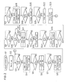
- Fig. 1 is a time chart showing the controlling procedures during copying operation;
- Fig. 2 is a flow chart showing the controlling procedures during copying operation;
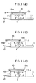
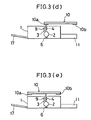
- Fig. 3 (a) to 3 (e) are explanatory views illustrating the movement of an original glass plate in the course of copying operation;
- Fig. 4 is an explanatory view showing the internal arrangement of a copying apparatus; and
- Fig. 5 is a circuit diagram showing a high voltage system which applies a high voltage trigger to both an electrostatic charger and an image transferring charger.
- One embodiment of the invention will now be described with reference to Figs. 1 through 5.
- An electrostatic copying apparatus as an image forming apparatus, as Figs. 3 (a) to 3 (e), and 4 show, includes a
main body 1 of the copying apparatus or image forming apparatus. Aphotoreceptor drum 2 is disposed within themain body 1 of the copying apparatus. Thephotoreceptor drum 2 is driven by a main motor MM not shown to rotate in the clockwise direction in Figs. 3 and 4. Disposed around thephotoreceptor drum 2 are anelectrostatic charger 3 as electrostatic means, a Selfoclens 4, a developingdevice 5 as developing means, a transferringcharger 6 as transferring means, acleaning device 7, and acharge removing lamp 8. Anexposure lamp 9 as a light source is disposed above the charge removing lamp. - An
original glass plate 10 is supported above themain body 1 of the copying apparatus so as to move in a feed direction which is the moving direction of theoriginal glass plate 10 during a scanning operation (the direction of arrow A) and also in a return direction (the direction of arrow B). - At the rear end of the
original glass plate 10 oriented in the feed direction, there is mounted, on the underside thereof, a first whitereflecting plate 10 a as a reflecting unit which reflects the light from theexposure lamp 9 to direct same toward an area between theelectrostatic charger 3 and the developingdevice 5 in thephotoreceptor drum 2 through the Selfoclens 4 when theoriginal glass plate 10 is positioned at an overrun position (Fig. 3 (d)) where its movement in the feed direction is terminated. - At the leading end of the
original glass plate 10, oriented in the feed direction, there is mounted, on the underside thereof, a second white reflectingplate 10b which reflects the light from theexposure lamp 9 to direct same toward the area between theelectrostatic charger 3 and the developingdevice 5 in thephotoreceptor drum 2 through the Selfoclens 4 when theoriginal glass plate 10 is positioned at a start position (Fig. 3 (d)) where its movement in the return direction is terminated. - On the
original glass plate 10 there are disposed, a home position sensor HPS for detecting the original glass plate being at its home position, a start position sensor SPS for detecting theoriginal glass plate 10 being at the start position (Fig. 3 (b)), and an overrun position sensor OPS for detecting theoriginal glass plate 10 being at the overrun position (Fig. 3(d)). These sensors are not shown in the drawings. - A
paper storing member 11 is disposed at one side of a lower portion of themain body 1 of the copying apparatus so thatcopying sheets 12 housed in thepaper storing member 11 are successively supplied, one by one, by means of afeed roller 13 during the process of copying. Eachsheet 12 fed through thefeed roller 13 is supplied to a paper stop roller 16 (hereinafter referred to as PS roller) through an incoming paper detecting switch (PIS) 15 for detecting the supply of thesheet 12 to thephotoreceptor drum 2. ThePS roller 16 supplies thesheet 12 to thephotoreceptor drum 2 by such timing as is synchronous with the transfer of a toner image from thephotoreceptor drum 2. - A fixing device not shown is disposed at the other side of the lower portion of the
main body 1 of the copying apparatus, and apaper discharge tray 17 is disposed in adjoining relation to the fixing device and in the exterior of themain body 1 of the copying apparatus. Further, an outgoing paper detecting switch POS, not shown, for detecting discharge of thecopying sheet 12 to thedischarge tray 17 is disposed in themain body 1 of the copying apparatus. - As Fig. 5 shows, the
electrostatic charger 3 is connected to ahigh voltage transformer 18 as high voltage application means, and the transferringcharger 6 is connected through aresistor 19 to thehigh voltage transformer 18 so that a high voltage trigger is applied from thehigh voltage transfomer 18 simultaneously to both theelectrostatic charger 3 and the transferringcharger 6. Above mentioned components which are housed in themain body 1 of the copying apparatus are controlled by control means, not shown, such as a microcomputer or the like. - Next, the manner of the operation of the copying apparatus will be explained.
- In a copying operation, the
original glass plate 10 supporting an original not shown is first moved from the home position (Fig. 3 (a)) to the start position (Fig. 3 (b)). Thereafter, theoriginal glass plate 10 is moved in the feed direction as the surface of thephotoreceptor drum 2 is charged by theelectrostatic charger 3 to a predetermined potential, whereby the original is scanned by the exposure lamp 9 (Fig. 3 (c)). Accordingly, a beam of light reflected from the original is projected on to the surface of thephotoreceptor drum 2 through the Selfoclens 4 so that an electrostatic latent image is formed on the surface of thephotorecptor drum 2. Subsequently, the electrostatic latent image is developed by toner particles supplied from the developingdevice 5, a toner image being thus formed on the surface ofphotoreceptor drum 2. - This is followed by supply of the
copying sheet 12 from thePS roller 16 to thephotoreceptor drum 2, and then the toner image on the surface of thephotoreceptor drum 2 is transferred onto thecopying sheet 12 by electrostatic discharge from the transferringcharger 6. During this transfer operation, theoriginal glass plate 10 is caused to stop at the overrun position shown in Fig. 3 (d) by the control means. A beam of light from theexposure lamp 9 is reflected by the white reflectingplate 10a to illuminate thephotoreceptor drum 2 so that the charge applied by theelectrostatic charger 3 to the surface of thephotoreceptor drum 2 is removed even during the period of toner image transferring. - Upon completion of the transfer operation, the
original glass plate 10 is caused to return to the home position (Fig. 3 (e)), and at the same time thesheet 12 is transported to the fixing device in which image fixation is carried out. Thereafter, thesheet 12 is discharged onto thedischarge tray 17. Any residual toner present on the surface of thephotoreceptor drum 2 is removed by thecleaning device 7, while any residual charge on the surface of thephotoreceptor drum 2 is removed by a beam of light projected from thecharge removing lamp 8. - The controlling procedures during the process of copying will now be described in detail with reference to Figs. 1 and 2. For the convenience of explanation, step numbers corresponding to the steps in the flow chart of Fig. 2 are given at the top of the time chart of Fig. 1.
- In the flow chart of Fig. 2, when a power supply not shown is turned on (S1), warming up, e.g., heating, of the fixing device is executed (S2), and a standby period follows (S3) until a print switch PSW, not shown, is turned on to command a copying operation.
- When the print switch PSW is turned on (Fig. 1 (a)), the main motor MM and the
exposure lamp 9 are turned on (Figs. 1 (b) and 1 (c)) and a timer T1 is set (S4). - Subsequently, decision is made whether the time T1 has ended its counting operation or not (S5). If it is determined that counting operation by the timer T1 has ended, an original glass plate return solenoid TRS not shown is turned on (Fig. 1 (e)) and accordingly a clutch between a drive mechanism for the
original glass plate 10 and the main motor MM is connected, so that the movement of theoriginal glass plate 10 in the return direction(B direction) is commenced and simultaneously a paper feed roller driving solenoid PFS not shown is turned on (Fig. 1 (f)), power being thus transmitted to thepaper feed roller 13 so that the copyingsheet 12 is fed from the paper storing member 11 (S6). - Then, a standby period follows until the start position sensor SPS is turned on (S7). When the start position sensor SPS is turned on (Fig. 1 (k)), the original glass plate return solenoid TRS is turned off, whereupon the movement of the
original glass plate 10 is terminated so that theglass plate 10 stops at the start position. Simultaneously, thehigh voltage transformer 18 is turned on so that application of a high voltage trigger to theelectrostatic charger 3 and transferringcharger 6 is commenced (Fig. 1 (h)) and a timer T2 is set (S8). - Then, a standby period follows until the timer T2 ends its counting operation (S9). During this standby period, corona discharge from both the
electrostatic charger 3 and the transferringcharger 6 is applied to thephotoreceptor drum 2. The charge applied to the surface of thephotoreceptor drum 2 by theelectrostatic charger 3 is removed as the light from theexposure lamp 9 is reflected by the white reflectingplate 10b on theoriginal glass plate 10 to illuminate thephotoreceptor drum 2 through theSelfoc lens 4. The charge applied to thephotoreceptor drum 2 by the transferringcharger 6 is removed by a beam of light from thecharge removing lamp 8. - At aforesaid steps S8 and S9, cleaning of the
photoreceptor drum 2 is carried out. This cleaning operation may be carried out during the period of warming up at step S2. - Thereafter, when counting operation by the timer T2 is terminated, decision is made whether or not the
sheet 12 has passed the incoming paper detecting switch (PIS) 15 thereby turning on the incoming paper detecting switch (PIS) 15 (S10). If it is determined that the incomingpaper detecting switch 15 is not ON, decision is made that a paper jam has been caused, and the program advances to a paper jam handling routine. - If, on the other hand, the incoming
paper detecting switch 15 is ON (Fig. 1 (i)), decision is made that there is no paper jam, whereupon an original glass plate feed solenoid TFS, not shown, is turned on to start power transmission for moving theoriginal glass palte 10 in the feed direction and, simultaneously, a PS roller driving solenoid PSS, not shown, is turned on to transmit power to the PS roller 16 (Figs. 1 (d), 1 (g)) (S11). Accordingly, theoriginal glass plate 10 is moved in the feed direction via the home position for an original scanning operation and, at the same time,thesheet 12 is supplied from thePS roller 16 onto thephotoreceptor drum 2. - As original scanning carried out, an electrostatic latent image is formed on the surface of the
photoreceptor drum 2 as already mentioned, the electrostatic latent image is sequentially developed by toner particles fed from the developingdevice 5. - Subsequently, decision is made whether or not the trailing end of the
sheet 12 has left the incomingpaper detecting switch 15 with the result that the (PIS) 15 has been turned off (S12). If it is determined that the incomingpaper detecting switch 15 is off, a timer T3 is set for counting the time required up to the end of transfer operation (S13) and then decision is made whether or not the overrun position sensor OPS has been turned on (S14). - If it is determined that the overrun position sensor OPS is ON (Fig. 1 (1)}, the original glass plate feed solenoid TFS is turned off so that the
original glass plate 10 is stopped at the overrun position, and simultaneously a timer T5 is set (S15). This standby time setting by the timer T5 is set to prevent the start of movement of theoriginal glass plate 10 in the return direction when theoriginal glass plate 10 is still moving in the feed direction of feed because of some delay in the turning off action of the original glass plate feed solenoid TFS or under an inertia force of theoriginal glass plate 10. - When the
original glass plate 10 has reached the overrun position to complete the scanning of the original and the formation of a toner image through development of the electrostatic latent image, the toner image is transferred, by corona discharge from the transferringcharger 6, onto copying thesheet 12 fed to thephotoreceptor drum 2. During this stage of imge transferring, there is still continued supply of a high voltage trigger to both theelectrostatic charger 3 and the transferringcharger 6 by the common high voltage transformer, and therefore thephotoreceptor drum 2 is naturally subjected to the application of corona charge from theelectrostatic charger 3. As mentioned above, however, in the stage of image transferring, theoriginal glass plate 10 stays at the overrun position and there is continued emission of light from theexposure lamp 9; therefore, the light from theexposure lamp 9 is reflected by the white reflectingplate 10a on theoriginal glass plate 10 to illuminate thephotoreceptor drum 2 over its area between theelectrostatic charger 3 and the developingdevice 5 through theSelfoc lens 4, so that the charge which is applied to the non-image area of thephotoreceptor drum 2 by theelectrostatic charger 3 during the transferring stage is effectively removed. - Subsequently, decision is made whether or not the timer T5 has completed its counting operation. If it is determined that the counting by the timer T5 is completed, then decision is made whether or not the timer T3 has completed its counting operation (S17). If the timer T3 has completed the counting, it is considered that the stage of transfer has been ended, and accordingly the PS roller drive solenoid PSS is turned off to terminate the rotation of the
PS roller 16 and the application of high voltage trigger to both theelectrostatic charger 3 and the transferringcharger 6 by thehigh voltage transformer 18 is discontinued. Further, the original glass plate return solenoid TRS is turned on to cause theoriginal glass palte 10 to start its movement in the feed direction (S18). - Then, decision is made whether or not the home position sensor HPS has been turned on (S19). If it is determined that the
original glass plate 10 has returned to the home position, the home position sensor HPS being thus turned on (Fig. 1 (m)), a timer T4 is set (S20). Thereafter, when the timer T4 ends counting operation (S21), the original glass plate return solenoid TRS is turned off to terminate the movement of the original glass plate 10 (S22); and a step is taken for copy cycle ending (S23), the program then returning to step S3. - As described above, the image forming apparatus according to the invention which comprises, in a main body thereof, a light source, a photoreceptor, charging means for electrostatically charging the surface of the photoreceptor, developing means for supplying toner particles to the surface of the photoreceptor, transferring means for transferring onto a copying sheet a toner image formed on the surface of the photoreceptor, and high-voltage applying means for applying a high voltage trigger to both said charging means and said transferring means simultaneously, said apparatus being designed to execute original scanning as an original glass plate is moved with respect to said main body, is characterized in comprising a reflecting unit for reflecting the light from the light source to illuminate the surface of the photoreceptor at an area between the charging means and the developing means, said reflecting unit being disposed at a position correcponding to the trailing end of the original glass plate in its forward movement for original scanning, and control means for causing the original glass plate to stop at an original scanning completing station after the end of the original scanning until the end of the stage of image transferring by the transferring means and for causing the light source to continue light emission so that the charge which is applied to a non-image area of the photoreceptor surface after the end of the original scanning until the end of the stage of image transferring is removed by the light from the light source that is reflected by said reflecting unit to illuminate the surface of the photoreceptor.
- The image forming apparatus further comprises a paper detecting switch for detecting the presence or absence of a copying sheet, said switch being disposed in a traveling path of a copying sheet at a location before the station at which the toner image transferring is executed, and a timer for counting a period of time corresponding to the time involved after a copying sheet passes the position of said paper detecting switch until it passes the toner image transfer station said control means being adapted to cause the charge applied to the non-image area of the photoreceptor surface to be removed by the light from the light source until the timing up of said timer.
- Said control means may be of such an arrangement that if, at the end of the stage of toner image transferring onto the copying sheet, a predetermined time has not elapsed after the original glass plate is stopped, the predetermined time is allowed to elapse so that the original glass plate is caused to return to its predetermined position after the original glass plate is definitely stopped.
- In another embodiment, the image forming apparatus comprising, in a main body thereof, a light source, a photoreceptor, charging means for electrostatically charging the surface of the photoreceptor, developing means for supplying toner particles to the surface of the photoreceptor, transferring means for transferring onto a copying sheet a toner image formed on the surface of the photoreceptor, and high-voltage applying means for applying a high voltage trigger to both said charging means and said transferring means, said apparatus being designed to execute original scanning as an original glass plate is moved with respect to said main body, is characterized in comprising a reflecting unit for reflecting the light from the light source to illuminate the surface of the photoreceptor at an area between the charging means and the developing means, said reflecting unit being disposed at a position corresponding to the leading end of the original glass plate in its forward movement for original scanning, and control means for causing the original glass plate to stop at an original scanning starting station prior to the start of the original scanning and for causing the light source to emit light so that the charge which is applied to a non-image area of the photoreceptor surface until the start of the original scanning is removed by the light from the light source that is reflected by said reflecting unit to illuminate the surface of the photoreceptor, thereby cleaning the photoreceptor.
- According to the invention, as above described, a reflecting device for reflecting the light from the light source is disposed at the rear end of the original setting glass plate in the moving direction of the original glass plate during an original scanning operation, and it is arranged that the original glass plate stops at the scanning end position after the end of the scanning operation until the end of the image transferring operation by the transferring means and that light emission from the light source is continued until the end of the transferring stage, so that after the end of the scanning operation until the end of the transferring operation, the light reflected from the reflecting device is directed toward the non-image area of the photoreceptor surface between the electrostatic charging means and the developing means, thereby removing, by the reflected light from the reflecting device, the charge applied to the non-image area of the photoreceptor surface by the electrostatic charging means, which continues to carry out corona discharge, in conjunction with the transfer means, even after the end of the scanning operation.
- In this case, the reflecting device may be securely fixed on the original glass plate, there being no necessity of providing an independent light source for blank exposure. Therefore, where a common high voltage application means is employed for applying a high voltage trigger to both the electrostatic charging means and the transferring means, the arrangement necessary for blank exposure until the end of the transfer operation can be much more simplified than the prior art arrangement. Further, the arrangement of the invention makes it possible to manufacture the apparatus at a lower cost.
- Further, in the image forming apparatus of the invention, the arrangement for blank exposure may be simplified, said blank exposure being executed for removing the charge which has been applied to the non-image area of the photoreceptor surface by the cleaning means so that cleaning of the photoreceptor prior to the start of an original scanning operation is performed.
- Further, according to the invention, the completion of transferring a toner image formed on the photoreceptor surface onto a copying sheet is accurately detected thereby to achieve an accurate and precise blank exposure.
- Further, it is possible to prevent the original glass plate from being controlled not so as to move in the return direction when the original glass plate is still moving in the feed direction due to a delay in solenoid action for controlling the movement of the original glass plate or due to the inertia force of the original glass plate, thereby to positively prevent the apparatus from being damaged or otherwise.
- The invention being thus described, it will be obvious that the same may be varied in many ways. Such variations are not to be regarded as a departure from the scope of the invention.
- There are described above novel features which the skilled man will appreciate give rise to advantages. These are each independent aspects of the invention to be covered by the present application, irrespective of whether or not they are included within the scope of the following claims.
Claims (5)
Applications Claiming Priority (2)
| Application Number | Priority Date | Filing Date | Title |
|---|---|---|---|
| JP63135123A JPH01303461A (en) | 1988-05-31 | 1988-05-31 | Image forming device |
| JP135123/88 | 1988-05-31 |
Publications (3)
| Publication Number | Publication Date |
|---|---|
| EP0345033A2 true EP0345033A2 (en) | 1989-12-06 |
| EP0345033A3 EP0345033A3 (en) | 1990-12-12 |
| EP0345033B1 EP0345033B1 (en) | 1993-11-10 |
Family
ID=15144361
Family Applications (1)
| Application Number | Title | Priority Date | Filing Date |
|---|---|---|---|
| EP89305466A Expired - Lifetime EP0345033B1 (en) | 1988-05-31 | 1989-05-31 | Image forming apparatus |
Country Status (6)
| Country | Link |
|---|---|
| US (1) | US4920379A (en) |
| EP (1) | EP0345033B1 (en) |
| JP (1) | JPH01303461A (en) |
| KR (1) | KR920009698B1 (en) |
| CN (1) | CN1021854C (en) |
| DE (1) | DE68910584T2 (en) |
Cited By (1)
| Publication number | Priority date | Publication date | Assignee | Title |
|---|---|---|---|---|
| EP0563478A2 (en) * | 1992-04-03 | 1993-10-06 | Canon Kabushiki Kaisha | Image forming apparatus having image transfer electrode contactable to transfer material |
Families Citing this family (3)
| Publication number | Priority date | Publication date | Assignee | Title |
|---|---|---|---|---|
| JP2595824B2 (en) * | 1991-02-01 | 1997-04-02 | 富士ゼロックス株式会社 | Image forming cartridge |
| JP6311307B2 (en) * | 2013-12-27 | 2018-04-18 | セイコーエプソン株式会社 | OPTICAL MODULE, ELECTRONIC DEVICE, AND OPTICAL MODULE DRIVING METHOD |
| CN105739273B (en) * | 2014-12-24 | 2019-01-04 | 株式会社理光 | Image forming apparatus |
Citations (3)
| Publication number | Priority date | Publication date | Assignee | Title |
|---|---|---|---|---|
| GB2012073A (en) * | 1978-01-07 | 1979-07-18 | Ricoh Kk | Electrophotographic copying apparatus |
| JPS5710160A (en) * | 1980-06-20 | 1982-01-19 | Canon Inc | Copying device |
| JPS61134773A (en) * | 1984-12-06 | 1986-06-21 | Ricoh Co Ltd | Corona charging device |
Family Cites Families (7)
| Publication number | Priority date | Publication date | Assignee | Title |
|---|---|---|---|---|
| JPS5527885Y2 (en) * | 1975-09-09 | 1980-07-03 | ||
| JPS6049906B2 (en) * | 1979-05-29 | 1985-11-05 | 松下電器産業株式会社 | High voltage power supply for copying machines |
| JPS5738442A (en) * | 1980-08-20 | 1982-03-03 | Fuji Xerox Co Ltd | Method for preventing image transfer in copying machine |
| JPS58217962A (en) * | 1982-06-14 | 1983-12-19 | Canon Inc | Electrophotographic copying machine |
| JPS6117166A (en) * | 1984-07-02 | 1986-01-25 | Konishiroku Photo Ind Co Ltd | Electronic copying machine |
| JPS62129869A (en) * | 1985-11-30 | 1987-06-12 | Mita Ind Co Ltd | Copying machine |
| JPS62174779A (en) * | 1986-01-28 | 1987-07-31 | Konishiroku Photo Ind Co Ltd | Electrostatic recording device |
-
1988
- 1988-05-31 JP JP63135123A patent/JPH01303461A/en active Pending
-
1989
- 1989-05-29 KR KR1019890007189A patent/KR920009698B1/en not_active IP Right Cessation
- 1989-05-31 CN CN89104633A patent/CN1021854C/en not_active Expired - Lifetime
- 1989-05-31 DE DE68910584T patent/DE68910584T2/en not_active Expired - Lifetime
- 1989-05-31 EP EP89305466A patent/EP0345033B1/en not_active Expired - Lifetime
- 1989-05-31 US US07/359,276 patent/US4920379A/en not_active Expired - Lifetime
Patent Citations (3)
| Publication number | Priority date | Publication date | Assignee | Title |
|---|---|---|---|---|
| GB2012073A (en) * | 1978-01-07 | 1979-07-18 | Ricoh Kk | Electrophotographic copying apparatus |
| JPS5710160A (en) * | 1980-06-20 | 1982-01-19 | Canon Inc | Copying device |
| JPS61134773A (en) * | 1984-12-06 | 1986-06-21 | Ricoh Co Ltd | Corona charging device |
Non-Patent Citations (2)
| Title |
|---|
| PATENT ABSTRACTS OF JAPAN, vol. 10, no. 330 (P-514)[2386], 11th November 1986; & JP-A-61 134 773 (RICOH CO., LTD) 21-06-1986 * |
| PATENT ABSTRACTS OF JAPAN, vol. 6, no. 70 (P-113)[948], 6th May 1982; & JP-A-57 010 160 (CANON K.K.) * |
Cited By (2)
| Publication number | Priority date | Publication date | Assignee | Title |
|---|---|---|---|---|
| EP0563478A2 (en) * | 1992-04-03 | 1993-10-06 | Canon Kabushiki Kaisha | Image forming apparatus having image transfer electrode contactable to transfer material |
| EP0563478A3 (en) * | 1992-04-03 | 1994-05-18 | Canon Kk | Image forming apparatus having image transfer electrode contactable to transfer material |
Also Published As
| Publication number | Publication date |
|---|---|
| DE68910584D1 (en) | 1993-12-16 |
| EP0345033B1 (en) | 1993-11-10 |
| JPH01303461A (en) | 1989-12-07 |
| CN1021854C (en) | 1993-08-18 |
| US4920379A (en) | 1990-04-24 |
| DE68910584T2 (en) | 1994-05-19 |
| CN1039314A (en) | 1990-01-31 |
| EP0345033A3 (en) | 1990-12-12 |
| KR920009698B1 (en) | 1992-10-22 |
| KR890017584A (en) | 1989-12-16 |
Similar Documents
| Publication | Publication Date | Title |
|---|---|---|
| EP0345033A2 (en) | Image forming apparatus | |
| EP0226369B2 (en) | Image forming apparatus with means for controlling the charge area of a photoreceptor | |
| US4711552A (en) | Synchronizing electrostatic copy formation | |
| US4611903A (en) | Image forming apparatus with reduced image forming time | |
| US4548491A (en) | Counterbalance subsystem to accommodate a variable center of gravity | |
| JP2589479B2 (en) | Light source control method and apparatus in image forming apparatus | |
| US5239351A (en) | Reproduction apparatus having an adjustable detack roller assembly | |
| US4682879A (en) | Electrophotographic copier | |
| US4763159A (en) | Multimagnification optical system in a dual mode copier | |
| JP2957369B2 (en) | Image forming device | |
| JP2605302B2 (en) | Copier | |
| JP2620802B2 (en) | Image forming device | |
| JPH0731249Y2 (en) | Image forming device | |
| JPH065399B2 (en) | Exposure equipment | |
| JP2750702B2 (en) | Image forming device | |
| JPH0887221A (en) | Image forming device | |
| JPH0213303B2 (en) | ||
| JPH0216577A (en) | Copying device | |
| JPS61221736A (en) | Copying device | |
| JPH0517045A (en) | Electrophotographic apparatus | |
| JPH04115280A (en) | Fixing device for image forming device | |
| JPS626286A (en) | Fixing device | |
| JPH03118568A (en) | Automatically exposing copying machine | |
| JPS61186947A (en) | Copying device | |
| JPS63204287A (en) | Image forming device |
Legal Events
| Date | Code | Title | Description |
|---|---|---|---|
| PUAI | Public reference made under article 153(3) epc to a published international application that has entered the european phase |
Free format text: ORIGINAL CODE: 0009012 |
|
| 17P | Request for examination filed |
Effective date: 19890623 |
|
| AK | Designated contracting states |
Kind code of ref document: A2 Designated state(s): DE FR GB IT |
|
| PUAL | Search report despatched |
Free format text: ORIGINAL CODE: 0009013 |
|
| AK | Designated contracting states |
Kind code of ref document: A3 Designated state(s): DE FR GB IT |
|
| 17Q | First examination report despatched |
Effective date: 19920717 |
|
| GRAA | (expected) grant |
Free format text: ORIGINAL CODE: 0009210 |
|
| AK | Designated contracting states |
Kind code of ref document: B1 Designated state(s): DE FR GB IT |
|
| REF | Corresponds to: |
Ref document number: 68910584 Country of ref document: DE Date of ref document: 19931216 |
|
| ET | Fr: translation filed | ||
| ITF | It: translation for a ep patent filed |
Owner name: DR. ING. A. RACHELI & C. |
|
| PLBE | No opposition filed within time limit |
Free format text: ORIGINAL CODE: 0009261 |
|
| STAA | Information on the status of an ep patent application or granted ep patent |
Free format text: STATUS: NO OPPOSITION FILED WITHIN TIME LIMIT |
|
| 26N | No opposition filed | ||
| REG | Reference to a national code |
Ref country code: GB Ref legal event code: IF02 |
|
| PGFP | Annual fee paid to national office [announced via postgrant information from national office to epo] |
Ref country code: DE Payment date: 20080605 Year of fee payment: 20 |
|
| PGFP | Annual fee paid to national office [announced via postgrant information from national office to epo] |
Ref country code: IT Payment date: 20080527 Year of fee payment: 20 |
|
| PGFP | Annual fee paid to national office [announced via postgrant information from national office to epo] |
Ref country code: GB Payment date: 20080604 Year of fee payment: 20 |
|
| REG | Reference to a national code |
Ref country code: GB Ref legal event code: PE20 Expiry date: 20090530 |
|
| PG25 | Lapsed in a contracting state [announced via postgrant information from national office to epo] |
Ref country code: GB Free format text: LAPSE BECAUSE OF EXPIRATION OF PROTECTION Effective date: 20090530 |
|
| PGFP | Annual fee paid to national office [announced via postgrant information from national office to epo] |
Ref country code: FR Payment date: 20080514 Year of fee payment: 20 |