EP0344534B1 - Method of monitoring the quality of digital signals in sections of a transmission line - Google Patents
Method of monitoring the quality of digital signals in sections of a transmission line Download PDFInfo
- Publication number
- EP0344534B1 EP0344534B1 EP89108980A EP89108980A EP0344534B1 EP 0344534 B1 EP0344534 B1 EP 0344534B1 EP 89108980 A EP89108980 A EP 89108980A EP 89108980 A EP89108980 A EP 89108980A EP 0344534 B1 EP0344534 B1 EP 0344534B1
- Authority
- EP
- European Patent Office
- Prior art keywords
- digital signal
- code word
- bip
- stm
- auxiliary
- Prior art date
- Legal status (The legal status is an assumption and is not a legal conclusion. Google has not performed a legal analysis and makes no representation as to the accuracy of the status listed.)
- Expired - Lifetime
Links
- 238000012544 monitoring process Methods 0.000 title claims abstract description 15
- 238000000034 method Methods 0.000 title claims abstract description 5
- 230000005540 biological transmission Effects 0.000 title claims description 11
- 230000001360 synchronised effect Effects 0.000 claims abstract description 9
- 230000007812 deficiency Effects 0.000 claims 2
- 230000007257 malfunction Effects 0.000 description 3
- 230000007547 defect Effects 0.000 description 2
- 230000015572 biosynthetic process Effects 0.000 description 1
- 238000001514 detection method Methods 0.000 description 1
- 239000012535 impurity Substances 0.000 description 1
- 230000007774 longterm Effects 0.000 description 1
Images
Classifications
-
- H—ELECTRICITY
- H04—ELECTRIC COMMUNICATION TECHNIQUE
- H04J—MULTIPLEX COMMUNICATION
- H04J3/00—Time-division multiplex systems
- H04J3/02—Details
- H04J3/14—Monitoring arrangements
-
- H—ELECTRICITY
- H04—ELECTRIC COMMUNICATION TECHNIQUE
- H04J—MULTIPLEX COMMUNICATION
- H04J2203/00—Aspects of optical multiplex systems other than those covered by H04J14/05 and H04J14/07
- H04J2203/0001—Provisions for broadband connections in integrated services digital network using frames of the Optical Transport Network [OTN] or using synchronous transfer mode [STM], e.g. SONET, SDH
- H04J2203/0064—Admission Control
- H04J2203/0067—Resource management and allocation
- H04J2203/0071—Monitoring
Definitions
- Quality monitoring includes, on the one hand, the detection and reporting of defects in the digital signal or its absence and, on the other hand, the determination of long-term changes in the transmission properties of the routes.
- British patent GB-A-1 401 261 describes a multiplex data transmission system in which disturbed bits are transmitted by intermediate stations without correction in order to be able to carry out error analysis and alarming.
- a synchronous digital signal is furthermore from the CCITT recommendation designs G.70X, G.70Y and G.70Z, which have led to the CCITT recommendations G.707, 708 and 709 (CCITT-Blue Book Volume III, Fascicle III.4) -Hierarchy known.
- Digital signals of the lowest hierarchical level have a bit rate of 155.52 Mbit / s and a pulse frame, which is called the synchronous transport module STM-1. This consists of a section overhead, an administration unit and an administration unit pointer unit pointer).
- a virtual container can be inserted into the administrative unit, the beginning of which indicates the administrative unit pointer.
- the virtual container in turn consists of a path frame header (path overhead) and a container in which a 139.264 Mbit / s signal is accommodated.
- This virtual container contains 2349 bytes of 8 bits each.
- a BIP-8 code word (bit-interleaved-parity-8 code) for parity monitoring, in which it is recorded whether the sum of the logical states of one bit position of every 2349 byte is even or odd , (CCITT, Blue Book, Volume III, Fascicle III.4 (1989), page 120, Rec. G.708, 5.2.1.6).
- This BIP-8 code word is transmitted unchanged from the digital signal source to the digital signal sink in the case of trouble-free operation.
- a standardized B1 byte is newly formed in each regenerator. This monitoring therefore only extends from regenerator to regenerator.
- a standardized B2 byte is formed at least at the places where the pointer content is reset, which is done in higher multiplex devices and possibly also in line terminals.
- the invention is based on the object of specifying a monitoring method which detects sections between digital signal distributors and between the digital signal source or the digital signal sink and the adjacent digital signal distributor.
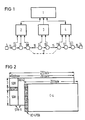
- Fig. 1 shows a centrally controlled network replacement switching system with a network management center 1, with regional centers 2-4, with a digital signal source 5, with digital signal distributors 6-13, with a digital signal sink 14, with a transmission link 15, with a fault point 16 and with an alternative route 17.
- a digital signal is transmitted from the digital signal source 5 to the digital signal sink 14 via the transmission link 15. Between the digital signal source 5 and the impurity 16, the digital signal is without defects.
- the digital signal distributors 6-8 report no malfunction to the regional center 2.
- the digital signal distributors 9-13 located after the malfunction 16 recognize the malfunction and report this to the regional centers 3 and 4.
- the network management center 1 initiates the switching of the Alternative route 17.
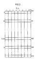
- the path frame header VC-4 POH contains bytes J1, B3, C2, E1, F2 and H4, which according to CCITT are already intended for a specific use. However, bytes Z3, Z4 and Z5 are still freely available.
- Fig. 3 all 2349 bytes of the virtual container VC-4 are shown one below the other.
- the top byte is a standardized J1 byte, which is of no interest here; otherwise bytes B3, Z4 and Z5 are highlighted.
- Each digital signal distributor 6 to 13 in FIG. 1 forms a new additional BIP-8 code word, compares this with the received one, reports a possible error or the current state to its regional headquarters 2 to 4 and feeds an additional BIP-8 Code word B4 and a correction code word for the outgoing line into the Z4 and Z5 time slots.
- the network management center can record the current situation on the basis of the messages from the digital signal distributors 2 to 13. When storing the messages, it can also provide quality information over longer periods of time.
Abstract
Description
Eine Qualitätsüberwachung beinhaltet einerseits die Feststellung und Meldung von Mängeln am Digitalsignal oder dessen Ausbleiben und andererseits die Ermittlung von langfristigen Änderungen der Übertragungseigenschaften der Strecken.Quality monitoring includes, on the one hand, the detection and reporting of defects in the digital signal or its absence and, on the other hand, the determination of long-term changes in the transmission properties of the routes.
Aus der Zeitschrift "telcom report", 10 (1987) Heft 2, Seiten 102 - 107, Bild 8 ist der Aufbau eines zentralgesteuerten Netzersatz-Schaltsystems bekannt. Bei Übertragungsstrecken mit Schaltstationen, die auch als Digitalsignalverteiler oder Cross-Connect-Einrichtungen bezeichnet werden, sind diese mit regionalen Zentralen verbunden, die wiederum mit einer Netzmanagement-Zentrale in Verbindung stehen. Meldet eine regionale Zentrale beispielsweise eine Unterbrechung der Übertragungsstrecke, dann veranlaßt die Netzmanagement-Zentrale die Schaltung eines Ersatzweges.From the magazine "telcom report", 10 (1987)
In dem britischen Patent GB-A-1 401 261 ist ein Multiplex-Datenübertragungssystem beschrieben, bei dem gestörte Bits von Zwischenstationen ohne Korrektur ausgesendet werden, um eine Fehleranalyse und Alamierung durchführen zu können.British patent GB-A-1 401 261 describes a multiplex data transmission system in which disturbed bits are transmitted by intermediate stations without correction in order to be able to carry out error analysis and alarming.
Aus den CCITT-Empfehlungsentwürfen G.70X, G.70Y und G.70Z, die zu den CCITT Empfehlungen G.707, 708 und 709 geführt haben (CCITT-Blue Book Volume III, Fascicle III.4), ist weiter eine synchrone Digitalsignal-Hierarchie bekannt. Digitalsignale der untersten Hierarchieebene weisen eine Bitrate von 155,52 Mbit/s und einen Pulsrahmen auf, der als synchroner Transportmodul STM-1 bezeichnet wird. Dieser besteht aus einem Abschnittsrahmenkopf (section overhead), einer Verwaltungseinheit (administration unit) und einem Verwaltungseinheitszeiger (administration unit pointer). In die Verwaltungseinheit kann ein virtueller Container eingefügt werden, dessen Anfang der Verwaltungseinheitszeiger angibt. Der virtuelle Container besteht wiederum aus einem Pfadrahmenkopf (path overhead) und einem Container, in dem ein 139,264-Mbit/s-Signal Platz findet.A synchronous digital signal is furthermore from the CCITT recommendation designs G.70X, G.70Y and G.70Z, which have led to the CCITT recommendations G.707, 708 and 709 (CCITT-Blue Book Volume III, Fascicle III.4) -Hierarchy known. Digital signals of the lowest hierarchical level have a bit rate of 155.52 Mbit / s and a pulse frame, which is called the synchronous transport module STM-1. This consists of a section overhead, an administration unit and an administration unit pointer unit pointer). A virtual container can be inserted into the administrative unit, the beginning of which indicates the administrative unit pointer. The virtual container in turn consists of a path frame header (path overhead) and a container in which a 139.264 Mbit / s signal is accommodated.
Dieser virtuelle Container enthält 2349 byte zu je 8 bit. Im genormten B3-Byte im Pfadrahmenkopf befindet sich zur Paritätsüberwachung ein BIP-8-Codewort (bit-interleaved-parity-8-code), in dem erfaßt ist, ob die Summe der logischen Zustände jeweils einer Bitstelle aller 2349 byte gerade oder ungerade ist, (CCITT, Blue Book, Volume III, Fascicle III.4 (1989), Seite 120, Rec. G.708, 5.2.1.6). Dieses BIP-8-Codewort wird bei störungsfreiem Betrieb unverändert von der Digitalsignalquelle bis zur Digitalsignalsenke übertragen.This virtual container contains 2349 bytes of 8 bits each. In the standardized B3 byte in the path frame header there is a BIP-8 code word (bit-interleaved-parity-8 code) for parity monitoring, in which it is recorded whether the sum of the logical states of one bit position of every 2349 byte is even or odd , (CCITT, Blue Book, Volume III, Fascicle III.4 (1989), page 120, Rec. G.708, 5.2.1.6). This BIP-8 code word is transmitted unchanged from the digital signal source to the digital signal sink in the case of trouble-free operation.
Im synchronen Transportmodul STM-1 sind noch weitere Überwachungen vorgesehen:
Ein genormtes B1-Byte wird in jedem Regenerator neu gebildet. Diese Überwachung reicht daher nur von Regenerator zu Regenerator. Ein genormtes B2-Byte wird zumindest an den Orten neu gebildet, wo der Zeigerinhalt neu gesetzt wird, was in höheren Multiplexgeräten und eventuell auch in Leitungsendgeräten erfolgt.Additional monitoring is provided in the synchronous transport module STM-1:
A standardized B1 byte is newly formed in each regenerator. This monitoring therefore only extends from regenerator to regenerator. A standardized B2 byte is formed at least at the places where the pointer content is reset, which is done in higher multiplex devices and possibly also in line terminals.
Der Erfindung liegt die Aufgabe zugrunde, ein Überwachungsverfahren anzugeben, das Abschnitte zwischen Digitalsignalverteilern und zwischen der Digitalsignalquelle bzw. der Digitalsignalsenke und dem benachbarten Digitalsignalverteiler erfaßt.The invention is based on the object of specifying a monitoring method which detects sections between digital signal distributors and between the digital signal source or the digital signal sink and the adjacent digital signal distributor.
Diese Aufgabe wird erfindungsgemäß mit den Merkmalen der Ansprüche 1 und 2 gelöst.This object is achieved with the features of
Anhand von Ausführungsbeispielen wird die Erfindung nachstehend näher erläutert.
- Fig. 1
- zeigt den Aufbau eines zentral gesteuerten Netzersatzschaltsystems,
- Fig. 2
- zeigt einen synchronen Transportmodul STM-1 mit einem virtuellen Container VC-4 und
- Fig. 3
- zeigt Bytes im virtuellen Container VC-4.
- Fig. 1
- shows the structure of a centrally controlled emergency power system,
- Fig. 2
- shows a synchronous transport module STM-1 with a virtual container VC-4 and
- Fig. 3
- shows bytes in the virtual container VC-4.
Fig. 1 zeigt ein zentralgesteuertes Netzersatz-Schaltsystem mit einer Netzmanagement-Zentrale 1, mit regionalen Zentralen 2-4, mit einer Digitalsignalquelle 5, mit Digitalsignalverteilern 6-13, mit einer Digitalsignalsenke 14, mit einer Übertragungsstrecke 15, mit einer Störstelle 16 und mit einem Ersatzweg 17.Fig. 1 shows a centrally controlled network replacement switching system with a
Ein Digitalsignal wird von der Digitalsignalquelle 5 zur Digitalsignalsenke 14 über die Übertragungsstrecke 15 übertragen. Zwischen der Digitalsignalquelle 5 und der Störstelle 16 ist das Digitalsignal ohne Mängel. Die Digitalsignalverteiler 6-8 melden keine Störung an die regionale Zentrale 2. Die nach der Störstelle 16 liegenden Digitalsignalverteiler 9-13 erkennen die Störung und melden diese an die regionalen Zentralen 3 und 4. Die Netzmanagement-Zentrale 1 veranlaßt aufgrund dieser Meldungen die Schaltung des Ersatzweges 17.A digital signal is transmitted from the
Fig. 2 zeigt einen synchronen Transportmodul STM-1 mit dem Abschnittsrahmenkopf SOH, der Verwaltungseinheit AU-4, dem Verwaltungseinheitszeiger AU-4 PTR, dem virtuellen Container VC-4, dem Pfadrahmenkopf VC-4 POH und dem Container C-4. Der Pfadrahmenkopf VC-4 POH enthält Bytes J1, B3, C2, E1, F2 und H4, die nach CCITT bereits für eine bestimmte Verwendung vorgesehen sind. Die Bytes Z3, Z4 und Z5 sind dagegen noch frei verfügbar.2 shows a synchronous transport module STM-1 with the section frame header SOH, the administration unit AU-4, the administration unit pointer AU-4 PTR, the virtual container VC-4, the path frame header VC-4 POH and the container C-4. The path frame header VC-4 POH contains bytes J1, B3, C2, E1, F2 and H4, which according to CCITT are already intended for a specific use. However, bytes Z3, Z4 and Z5 are still freely available.
In Fig. 3 sind alle 2349 Bytes des virtuellen Containers VC-4 untereinander dargestellt. Das oberste Byte ist ein genormtes hier nicht interessierendes J1-Byte; sonst sind die Bytes B3, Z4 und Z5 hervorgehoben. Im B3-Byte befindet sich ein BIP-8-Codewort als B3-Überwachung. Dies zeigt in jedem seiner 8 bit, ob die Bitanzahl der jeweiligen Bitstelle in den Bytes 1-261 und 263-2349 gerade oder ungerade ist. Dieses B3-Byte darf durch Einfügungen in die Z4- und Z5-Zeitschlitze nicht verfälscht werden.In Fig. 3 all 2349 bytes of the virtual container VC-4 are shown one below the other. The top byte is a standardized J1 byte, which is of no interest here; otherwise bytes B3, Z4 and Z5 are highlighted. There is a BIP-8 code word in the B3 byte as B3 monitoring. In each of its 8 bits, this shows whether the number of bits of the respective bit position in bytes 1-261 and 263-2349 is even or odd. This B3 byte must not be falsified by inserts into the Z4 and Z5 time slots.
Dies ist dann nicht der Fall, wenn in den Z4-und den Z5-Zeitschlitz das Zusatz-BIP-8-Codewort und ein gleiches Korrektur-Codewort eingefügt werden. Dies setzt voraus, daß bereits an der Quelle in die Z4-und Z5-Zeitschlitze gleiche Codewörter eingespeist wurden. War dies nicht der Fall, dann gingen diese Codewörter in die Bildung des B3-Bytes ein. Wenn man jetzt in den Z4-Zeitschlitz ein Zusatz-BIP-8-Codewort einfügt, muß man in jedem Digitalsignalverteiler 6-13 in den Z5-Zeitschlitz ein Korrektur-Codewort einfügen, dessen Bitfolge nach Auswertung des ankommenden Zusatz-BIP-8-Signals und des ankommenden Korrektursignals derart gewählt ist, daß die B3-Überwachung keine Veränderung merkt.This is not the case if the additional BIP-8 code word and an identical correction code word are inserted into the Z4 and Z5 time slots. This presupposes that identical code words have already been fed into the Z4 and Z5 time slots at the source. If this was not the case, then these code words were included in the formation of the B3 byte. If you now insert an additional BIP-8 code word in the Z4 time slot, you have to Insert a correction code word in each digital signal distributor 6-13 in the Z5 time slot, the bit sequence of which, after evaluating the incoming additional BIP-8 signal and the incoming correction signal, is selected such that the B3 monitoring does not notice any change.
Jeder Digitalsignalverteiler 6 bis 13 in Fig. 1 bildet ein neues Zusatz-BIP-8-Codewort, vergleicht dieses mit dem emfangenen, meldet einen eventuellen Fehler oder den gegenwärtigen Zustand an seine regionale Zentrale 2 bis 4 und speist ein Zusatz-BIP-8-Codewort B4 und ein Korrektur-Codewort für die abgehende Leitung in die Z4-und Z5-Zeitschlitze ein. Die Netzmanagement-Zentrale kann aufgrund der Meldungen der Digitalsignalverteiler 2 bis 13 die momentane Situation erfassen. Sie kann bei Speicherung der Meldungen aber auch Qualitätsangaben über längere Zeiträume machen.Each
Claims (2)
- Method for monitoring the quality of a digital signal in sections of a transmission link, characterised in that an STM-1 digital signal having a bit rate of 155.52 Mbit/s or a plurality of such signals in a digital signal (STM-N) of higher order of the synchronous digital signal heirarchy are monitored by a parity monitoring being performed with a bit-interleaved-parity-8 code word (BIP-8 code word) as a B3 byte of a path overhead (VC-4 POH) of a virtual container (VC-4), included in the STM-1 signal, for a bit rate of 149.72 Mbit/s, in that the sections between a digital signal source (5) of the digital signal (STM-1) and a first digital signal distributor (6), between respectively two neighbouring digital signal distributors (6, 7; 7, 8; 8, 9; 9, 10; 10, 11; 11, 12; 12, 13) and between the last digital signal distributor (13) and a digital signal sink (14) of the digital signal (STM-1) being chosen along a transmission link (15), in that the BIP-8 code word is fed on the one hand as an auxiliary BIP-8 code word (B4) and on the other hand as a correction code word into the two selected Z time slots (Z4, Z5) in the digital signal source (5) or in the first following digital signal distributor (6) - when the latter receives arbitary but identical code words in two selected Z time slots (Z4, Z5) of the path overhead (VC-4 POH), in that each digital signal distributor (6-13) which receives both auxiliary BIP-8 code words (B4) supplies two new auxiliary BIP-8 code words (B4), compares at least one of these code words with the corresponding received auxiliary BIP-8 code word (B4) and reports a deficiency or the present state to a central station (1-4) of a centrally controlled standby network switching system and in that the digital signal sink (14) evaluates at least one of the received auxiliary BIP-8 code words (B4).
- Method for monitoring the quality of a digital signal in sections of a transmission link, characterised in that an STM-1 digital signal having a bit rate of 155.52 Mbit/s or a plurality of such signals in a digital signal (STM-N) of higher order of the synchronous digital signal heirarchy are monitored by a parity monitoring being performed with a bit-interleaved-parity-8 code word (BIP-8 code word) as a B3 byte of a path overhead (VC-4 POH) of a virtual container (VC-4), included in the STM-1 signal, for a bit rate of 149.72 Mbit/s, in that the sections between a digital signal source (5) of the digital signal (STM-1) and a first digital signal distributor (6), between respectively two neighbouring digital signal distributors (6, 7; 7, 8; 8, 9; 9, 10; 10, 11; 11, 12; 12, 13) and between the last digital signal distributor (13) and a digital signal sink (14) of the digital signal (STM-1) being chosen along a transmission link (15), in that arbitrary code words are fed into two selected Z time slots (Z4, Z5) of the path overhead (VC-4 POH) in the digital signal source (5), in that it is determined in the first digital signal distributor in which bit positions inequality exists between the two code words, in that the BIP-8 code word is fed into one of the selected Z time slots (Z4) in the first digital signal distributor (6) as an auxiliary BIP-8 code word (B4) and the BIP-8 code word is fed into the other selected Z time slot (Z5) as a correction code word upon inversion in the determined bit positions of inequality, in that the auxiliary BIP-8 code word (B4) is newly formed in every other digital signal distributor (7-13), is compared with the incoming word and fed into the one Z time slot (Z4), in that, if there is coincidence, the received correction code word is newly fed into the other Z time slot (Z5), in that if there is non-coincidence, it is determined in which bit positions inequality exists between the received auxiliary BIP-8 code word (B4) and the received correction code word, and the auxiliary BIP-8 code word (B4) is fed into the other Z time slot (Z5) as a new correction code word upon inversion in the determined bit positions of inequality, in that a deficiency or the present state is in each case reported to a central station (1-4) of a centrally controlled standby network switching system and in that the digital signal sink (14) evaluates the auxiliary BIP-8 code word (B4).
Priority Applications (1)
| Application Number | Priority Date | Filing Date | Title |
|---|---|---|---|
| AT89108980T ATE93672T1 (en) | 1988-06-01 | 1989-05-18 | PROCEDURE FOR QUALITY MONITORING OF A DIGITAL SIGNAL IN SECTIONS OF A TRANSMISSION LINE. |
Applications Claiming Priority (2)
| Application Number | Priority Date | Filing Date | Title |
|---|---|---|---|
| DE3818716 | 1988-06-01 | ||
| DE3818716 | 1988-06-01 |
Publications (2)
| Publication Number | Publication Date |
|---|---|
| EP0344534A1 EP0344534A1 (en) | 1989-12-06 |
| EP0344534B1 true EP0344534B1 (en) | 1993-08-25 |
Family
ID=6355663
Family Applications (1)
| Application Number | Title | Priority Date | Filing Date |
|---|---|---|---|
| EP89108980A Expired - Lifetime EP0344534B1 (en) | 1988-06-01 | 1989-05-18 | Method of monitoring the quality of digital signals in sections of a transmission line |
Country Status (9)
| Country | Link |
|---|---|
| US (1) | US4964112A (en) |
| EP (1) | EP0344534B1 (en) |
| JP (1) | JPH0226428A (en) |
| AT (1) | ATE93672T1 (en) |
| AU (1) | AU590489B1 (en) |
| BR (1) | BR8902516A (en) |
| DE (1) | DE58905360D1 (en) |
| ES (1) | ES2042873T3 (en) |
| NO (1) | NO892206L (en) |
Families Citing this family (20)
| Publication number | Priority date | Publication date | Assignee | Title |
|---|---|---|---|---|
| DE59108457D1 (en) * | 1990-10-22 | 1997-02-13 | Siemens Ag | METHOD AND ARRANGEMENT FOR TRANSMITTING SYNCHRONIZING SIGNALS IN A NETWORK OF THE SYNCHRONOUS DIGITAL HIERARCHY |
| EP0483788B1 (en) * | 1990-10-31 | 1998-09-09 | Nec Corporation | A synchronous terminal station system |
| US5412709A (en) * | 1992-06-24 | 1995-05-02 | Charter Leasing Corporation | Digital telephone station line controller |
| GB9218011D0 (en) * | 1992-08-25 | 1992-10-14 | Northern Telecom Ltd | High availability leased lines |
| JPH06125331A (en) * | 1992-10-12 | 1994-05-06 | Nec Corp | Digital line terminator |
| FI98170C (en) * | 1992-12-02 | 1997-04-25 | Nokia Telecommunications Oy | Method for testing a network element used in a synchronous digital communication system |
| JP2897099B2 (en) * | 1993-09-20 | 1999-05-31 | 富士通株式会社 | Tandem connection maintenance method |
| DE4342559A1 (en) * | 1993-12-14 | 1995-06-22 | Kommunikations Elektronik | Digital data transmission method |
| US5787074A (en) * | 1996-06-28 | 1998-07-28 | Mci Communications Corporation | System and method for monitoring point activation |
| US6072777A (en) * | 1996-06-28 | 2000-06-06 | Mci Communications Corporation | System and method for unreported root cause analysis |
| US5768255A (en) * | 1996-06-28 | 1998-06-16 | Mci Communications Corporation | System and method for monitoring point identification |
| US5784359A (en) * | 1996-06-28 | 1998-07-21 | Mci Communications Corporation | System and method for unreported trouble isolation |
| US5864662A (en) * | 1996-06-28 | 1999-01-26 | Mci Communication Corporation | System and method for reported root cause analysis |
| US5796723A (en) * | 1996-06-28 | 1998-08-18 | Mci Communications Corporation | System and method for end-to-end threshold setting |
| EP1748617A3 (en) * | 1998-09-11 | 2011-02-09 | Hitachi, Ltd. | IP packet communication apparatus |
| JP3388464B2 (en) | 1999-11-04 | 2003-03-24 | 日本電気株式会社 | Optical transmission system using error correction and performance monitor method used therefor |
| JP2001186061A (en) * | 1999-12-24 | 2001-07-06 | Nec Corp | Transmission quality monitor system and method for monitoring transmission quality |
| US6975657B1 (en) * | 2000-09-21 | 2005-12-13 | Nortel Networks Limited | System and method for generation of large concatenated payloads |
| WO2002056513A1 (en) * | 2000-12-27 | 2002-07-18 | Fujitsu Limited | Path error detecting method and device therefor |
| RU2457538C1 (en) * | 2011-06-27 | 2012-07-27 | Федеральное государственное унитарное предприятие "18 Центральный научно-исследовательский институт" Министерства обороны Российской Федерации | Apparatus for technical monitoring of digital signals |
Family Cites Families (9)
| Publication number | Priority date | Publication date | Assignee | Title |
|---|---|---|---|---|
| GB1401261A (en) * | 1972-01-13 | 1975-07-16 | Siemens Ag | Data transmission systems |
| DE2556079C2 (en) * | 1975-12-12 | 1977-10-27 | Siemens AG, 1000 Berlin und 8000 München | Method for monitoring individual transmission sections for digital signals and arrangement for carrying out the method |
| FR2535135B1 (en) * | 1982-10-21 | 1988-03-25 | Servel Michel | DIGITAL PACKET MULTIPLEX SYNCHRONIZATION SYSTEM |
| CA1205561A (en) * | 1983-03-11 | 1986-06-03 | Kiichi Yamashita | Method of searching fault locations in digital transmission line |
| DE3401685A1 (en) * | 1984-01-19 | 1985-07-25 | Philips Patentverwaltung Gmbh, 2000 Hamburg | TROUBLESHOOTING METHOD |
| JPS61139134A (en) * | 1984-12-10 | 1986-06-26 | Nec Corp | Monitoring system for digital multiplexer |
| DE3619371A1 (en) * | 1986-06-09 | 1987-12-10 | Siemens Ag | Method for multiplexing and demultiplexing plesiochronous digital signals |
| DE3620835A1 (en) * | 1986-06-21 | 1987-12-23 | Philips Patentverwaltung | Method for monitoring a digital hierarchically structured information transmission network |
| AR241357A1 (en) * | 1986-06-27 | 1992-05-29 | Siemens Ag | Method for controlling the information transmission of switched four-wire connections, especially semi-permanent switched connections in digital tdm exchanges |
-
1989
- 1989-05-09 US US07/349,431 patent/US4964112A/en not_active Expired - Fee Related
- 1989-05-18 DE DE89108980T patent/DE58905360D1/en not_active Expired - Fee Related
- 1989-05-18 AT AT89108980T patent/ATE93672T1/en not_active IP Right Cessation
- 1989-05-18 EP EP89108980A patent/EP0344534B1/en not_active Expired - Lifetime
- 1989-05-18 ES ES89108980T patent/ES2042873T3/en not_active Expired - Lifetime
- 1989-05-31 JP JP1136267A patent/JPH0226428A/en active Pending
- 1989-05-31 NO NO89892206A patent/NO892206L/en unknown
- 1989-05-31 AU AU35973/89A patent/AU590489B1/en not_active Ceased
- 1989-06-01 BR BR898902516A patent/BR8902516A/en unknown
Also Published As
| Publication number | Publication date |
|---|---|
| EP0344534A1 (en) | 1989-12-06 |
| JPH0226428A (en) | 1990-01-29 |
| NO892206L (en) | 1989-12-04 |
| AU590489B1 (en) | 1989-11-02 |
| NO892206D0 (en) | 1989-05-31 |
| ATE93672T1 (en) | 1993-09-15 |
| DE58905360D1 (en) | 1993-09-30 |
| BR8902516A (en) | 1990-01-23 |
| US4964112A (en) | 1990-10-16 |
| ES2042873T3 (en) | 1993-12-16 |
Similar Documents
| Publication | Publication Date | Title |
|---|---|---|
| EP0344534B1 (en) | Method of monitoring the quality of digital signals in sections of a transmission line | |
| DE69532939T2 (en) | A trouble-free path switching arrangement and method | |
| DE3500512C2 (en) | Time division multiplex ring | |
| EP0342547B1 (en) | Method for generating an alarm suppression signal | |
| DE60221669T2 (en) | Packet switching for packet data transmission systems in a multi-channel radio arrangement | |
| DE3642141A1 (en) | METHOD FOR DECENTRALIZED POWER SUPPLY CIRCUIT | |
| EP0388495B1 (en) | Method of monitoring the quality of at least two transmission sections of a transmission link for digital signals and a device making use of such a method | |
| DE60125439T2 (en) | Information transmission network, traffic management method and node device | |
| EP0777351B1 (en) | Synchronous digital transmission system | |
| EP0503486B1 (en) | Line monitoring for SDH-signals | |
| EP0895680B1 (en) | Synchronous transmission system with fault location function and monitoring device therefor | |
| DE3937738A1 (en) | SUBSCRIBER CONNECTION NODE OF A DIGITAL MESSAGE TRANSMISSION SYSTEM | |
| EP1147632B1 (en) | METHOD FOR CONVERTING NxSTM-1 SIGNALS INTO STM-N SIGNALS | |
| DE69932810T2 (en) | RESERVES IN A TELECOMMUNICATIONS NETWORK | |
| EP0124906A2 (en) | Digital signal multiplex apparatus | |
| EP1108300A1 (en) | Telecommunications system and method for producing a master clock in the same | |
| DE69532882T2 (en) | SYNCHRONOUS TRANSMISSION SYSTEMS | |
| DE19627728A1 (en) | Network element and input / output unit for a synchronous transmission system | |
| DE19542230C2 (en) | Process for the selection of concatenated signals from received signals of the synchronous digital hierarchy | |
| DE3233221A1 (en) | CIRCUIT ARRANGEMENT FOR TRANSMITTING SIGNALS BETWEEN SUBSCRIBER CONNECTION LINES AND AT LEAST ONE TRANSMISSION LINE OF A SERVICE-INTEGRATED TELECOMMUNICATION SYSTEM | |
| DE60018779T2 (en) | SIGNALING FAULTS IN NEWS TRANSMISSION NETWORKS | |
| EP2282428B1 (en) | Method and system for switching of paths | |
| EP0993711B1 (en) | Method and circuit for adapting and switching through a data flow | |
| DE2556079B1 (en) | METHOD FOR MONITORING INDIVIDUAL TRANSMISSION SECTIONS FOR DIGITAL SIGNALS AND ARRANGEMENT FOR PERFORMING THE METHOD | |
| DE69736716T2 (en) | DISTRIBUTED DIGITAL CROSS CONNECT SYSTEM AND METHOD |
Legal Events
| Date | Code | Title | Description |
|---|---|---|---|
| PUAI | Public reference made under article 153(3) epc to a published international application that has entered the european phase |
Free format text: ORIGINAL CODE: 0009012 |
|
| AK | Designated contracting states |
Kind code of ref document: A1 Designated state(s): AT BE CH DE ES FR GB GR IT LI NL SE |
|
| 17P | Request for examination filed |
Effective date: 19900528 |
|
| 17Q | First examination report despatched |
Effective date: 19920724 |
|
| GRAA | (expected) grant |
Free format text: ORIGINAL CODE: 0009210 |
|
| AK | Designated contracting states |
Kind code of ref document: B1 Designated state(s): AT BE CH DE ES FR GB GR IT LI NL SE |
|
| REF | Corresponds to: |
Ref document number: 93672 Country of ref document: AT Date of ref document: 19930915 Kind code of ref document: T |
|
| REF | Corresponds to: |
Ref document number: 58905360 Country of ref document: DE Date of ref document: 19930930 |
|
| ITF | It: translation for a ep patent filed |
Owner name: STUDIO JAUMANN |
|
| GBT | Gb: translation of ep patent filed (gb section 77(6)(a)/1977) |
Effective date: 19931109 |
|
| ET | Fr: translation filed | ||
| REG | Reference to a national code |
Ref country code: ES Ref legal event code: FG2A Ref document number: 2042873 Country of ref document: ES Kind code of ref document: T3 |
|
| REG | Reference to a national code |
Ref country code: GR Ref legal event code: FG4A Free format text: 3009643 |
|
| PGFP | Annual fee paid to national office [announced via postgrant information from national office to epo] |
Ref country code: FR Payment date: 19940519 Year of fee payment: 6 |
|
| PGFP | Annual fee paid to national office [announced via postgrant information from national office to epo] |
Ref country code: BE Payment date: 19940520 Year of fee payment: 6 |
|
| PGFP | Annual fee paid to national office [announced via postgrant information from national office to epo] |
Ref country code: SE Payment date: 19940526 Year of fee payment: 6 |
|
| PGFP | Annual fee paid to national office [announced via postgrant information from national office to epo] |
Ref country code: NL Payment date: 19940531 Year of fee payment: 6 |
|
| PLBE | No opposition filed within time limit |
Free format text: ORIGINAL CODE: 0009261 |
|
| STAA | Information on the status of an ep patent application or granted ep patent |
Free format text: STATUS: NO OPPOSITION FILED WITHIN TIME LIMIT |
|
| PGFP | Annual fee paid to national office [announced via postgrant information from national office to epo] |
Ref country code: DE Payment date: 19940719 Year of fee payment: 6 |
|
| 26N | No opposition filed | ||
| PGFP | Annual fee paid to national office [announced via postgrant information from national office to epo] |
Ref country code: CH Payment date: 19940818 Year of fee payment: 6 |
|
| EAL | Se: european patent in force in sweden |
Ref document number: 89108980.7 |
|
| PGFP | Annual fee paid to national office [announced via postgrant information from national office to epo] |
Ref country code: GB Payment date: 19950420 Year of fee payment: 7 |
|
| PGFP | Annual fee paid to national office [announced via postgrant information from national office to epo] |
Ref country code: AT Payment date: 19950421 Year of fee payment: 7 |
|
| PGFP | Annual fee paid to national office [announced via postgrant information from national office to epo] |
Ref country code: ES Payment date: 19950427 Year of fee payment: 7 |
|
| PG25 | Lapsed in a contracting state [announced via postgrant information from national office to epo] |
Ref country code: SE Effective date: 19950519 |
|
| PGFP | Annual fee paid to national office [announced via postgrant information from national office to epo] |
Ref country code: GR Payment date: 19950530 Year of fee payment: 7 |
|
| PG25 | Lapsed in a contracting state [announced via postgrant information from national office to epo] |
Ref country code: LI Effective date: 19950531 Ref country code: CH Effective date: 19950531 Ref country code: BE Effective date: 19950531 |
|
| BERE | Be: lapsed |
Owner name: SIEMENS A.G. Effective date: 19950531 |
|
| PG25 | Lapsed in a contracting state [announced via postgrant information from national office to epo] |
Ref country code: NL Effective date: 19951201 |
|
| REG | Reference to a national code |
Ref country code: CH Ref legal event code: PL |
|
| NLV4 | Nl: lapsed or anulled due to non-payment of the annual fee |
Effective date: 19951201 |
|
| PG25 | Lapsed in a contracting state [announced via postgrant information from national office to epo] |
Ref country code: DE Effective date: 19960201 |
|
| EUG | Se: european patent has lapsed |
Ref document number: 89108980.7 |
|
| PG25 | Lapsed in a contracting state [announced via postgrant information from national office to epo] |
Ref country code: FR Effective date: 19960229 |
|
| REG | Reference to a national code |
Ref country code: FR Ref legal event code: ST |
|
| REG | Reference to a national code |
Ref country code: FR Ref legal event code: ST |
|
| PG25 | Lapsed in a contracting state [announced via postgrant information from national office to epo] |
Ref country code: GB Effective date: 19960518 Ref country code: AT Effective date: 19960518 |
|
| PG25 | Lapsed in a contracting state [announced via postgrant information from national office to epo] |
Ref country code: ES Free format text: LAPSE BECAUSE OF NON-PAYMENT OF DUE FEES Effective date: 19960520 |
|
| PG25 | Lapsed in a contracting state [announced via postgrant information from national office to epo] |
Ref country code: GR Free format text: THE PATENT HAS BEEN ANNULLED BY A DECISION OF A NATIONAL AUTHORITY Effective date: 19961130 |
|
| REG | Reference to a national code |
Ref country code: GR Ref legal event code: MM2A Free format text: 3009643 |
|
| GBPC | Gb: european patent ceased through non-payment of renewal fee |
Effective date: 19960518 |
|
| REG | Reference to a national code |
Ref country code: ES Ref legal event code: FD2A Effective date: 19990405 |
|
| PG25 | Lapsed in a contracting state [announced via postgrant information from national office to epo] |
Ref country code: IT Free format text: LAPSE BECAUSE OF NON-PAYMENT OF DUE FEES;WARNING: LAPSES OF ITALIAN PATENTS WITH EFFECTIVE DATE BEFORE 2007 MAY HAVE OCCURRED AT ANY TIME BEFORE 2007. THE CORRECT EFFECTIVE DATE MAY BE DIFFERENT FROM THE ONE RECORDED. Effective date: 20050518 |