EP0344286B1 - Suture anchor installation tool - Google Patents
Suture anchor installation tool Download PDFInfo
- Publication number
- EP0344286B1 EP0344286B1 EP89900754A EP89900754A EP0344286B1 EP 0344286 B1 EP0344286 B1 EP 0344286B1 EP 89900754 A EP89900754 A EP 89900754A EP 89900754 A EP89900754 A EP 89900754A EP 0344286 B1 EP0344286 B1 EP 0344286B1
- Authority
- EP
- European Patent Office
- Prior art keywords
- suture anchor
- installation tool
- barb
- suture
- bone
- Prior art date
- Legal status (The legal status is an assumption and is not a legal conclusion. Google has not performed a legal analysis and makes no representation as to the accuracy of the status listed.)
- Expired - Lifetime
Links
- QVHBYHHNDPVLJW-UHFFFAOYSA-N CC1(CN)C=COC=CC=C1 Chemical compound CC1(CN)C=COC=CC=C1 QVHBYHHNDPVLJW-UHFFFAOYSA-N 0.000 description 1
Images

Classifications
-
- A—HUMAN NECESSITIES
- A61—MEDICAL OR VETERINARY SCIENCE; HYGIENE
- A61B—DIAGNOSIS; SURGERY; IDENTIFICATION
- A61B17/00—Surgical instruments, devices or methods, e.g. tourniquets
- A61B17/04—Surgical instruments, devices or methods, e.g. tourniquets for suturing wounds; Holders or packages for needles or suture materials
- A61B17/0401—Suture anchors, buttons or pledgets, i.e. means for attaching sutures to bone, cartilage or soft tissue; Instruments for applying or removing suture anchors
-
- A—HUMAN NECESSITIES
- A61—MEDICAL OR VETERINARY SCIENCE; HYGIENE
- A61B—DIAGNOSIS; SURGERY; IDENTIFICATION
- A61B17/00—Surgical instruments, devices or methods, e.g. tourniquets
- A61B17/16—Bone cutting, breaking or removal means other than saws, e.g. Osteoclasts; Drills or chisels for bones; Trepans
- A61B17/1613—Component parts
- A61B17/1615—Drill bits, i.e. rotating tools extending from a handpiece to contact the worked material
-
- A—HUMAN NECESSITIES
- A61—MEDICAL OR VETERINARY SCIENCE; HYGIENE
- A61B—DIAGNOSIS; SURGERY; IDENTIFICATION
- A61B17/00—Surgical instruments, devices or methods, e.g. tourniquets
- A61B17/04—Surgical instruments, devices or methods, e.g. tourniquets for suturing wounds; Holders or packages for needles or suture materials
- A61B17/0401—Suture anchors, buttons or pledgets, i.e. means for attaching sutures to bone, cartilage or soft tissue; Instruments for applying or removing suture anchors
- A61B2017/0409—Instruments for applying suture anchors
-
- A—HUMAN NECESSITIES
- A61—MEDICAL OR VETERINARY SCIENCE; HYGIENE
- A61B—DIAGNOSIS; SURGERY; IDENTIFICATION
- A61B17/00—Surgical instruments, devices or methods, e.g. tourniquets
- A61B17/04—Surgical instruments, devices or methods, e.g. tourniquets for suturing wounds; Holders or packages for needles or suture materials
- A61B17/0401—Suture anchors, buttons or pledgets, i.e. means for attaching sutures to bone, cartilage or soft tissue; Instruments for applying or removing suture anchors
- A61B2017/0412—Suture anchors, buttons or pledgets, i.e. means for attaching sutures to bone, cartilage or soft tissue; Instruments for applying or removing suture anchors having anchoring barbs or pins extending outwardly from suture anchor body
-
- A—HUMAN NECESSITIES
- A61—MEDICAL OR VETERINARY SCIENCE; HYGIENE
- A61B—DIAGNOSIS; SURGERY; IDENTIFICATION
- A61B17/00—Surgical instruments, devices or methods, e.g. tourniquets
- A61B17/04—Surgical instruments, devices or methods, e.g. tourniquets for suturing wounds; Holders or packages for needles or suture materials
- A61B17/0401—Suture anchors, buttons or pledgets, i.e. means for attaching sutures to bone, cartilage or soft tissue; Instruments for applying or removing suture anchors
- A61B2017/0427—Suture anchors, buttons or pledgets, i.e. means for attaching sutures to bone, cartilage or soft tissue; Instruments for applying or removing suture anchors having anchoring barbs or pins extending outwardly from the anchor body
- A61B2017/0437—Suture anchors, buttons or pledgets, i.e. means for attaching sutures to bone, cartilage or soft tissue; Instruments for applying or removing suture anchors having anchoring barbs or pins extending outwardly from the anchor body the barbs being resilient or spring-like
-
- A—HUMAN NECESSITIES
- A61—MEDICAL OR VETERINARY SCIENCE; HYGIENE
- A61B—DIAGNOSIS; SURGERY; IDENTIFICATION
- A61B17/00—Surgical instruments, devices or methods, e.g. tourniquets
- A61B17/04—Surgical instruments, devices or methods, e.g. tourniquets for suturing wounds; Holders or packages for needles or suture materials
- A61B17/0401—Suture anchors, buttons or pledgets, i.e. means for attaching sutures to bone, cartilage or soft tissue; Instruments for applying or removing suture anchors
- A61B2017/0446—Means for attaching and blocking the suture in the suture anchor
- A61B2017/0458—Longitudinal through hole, e.g. suture blocked by a distal suture knot
-
- A—HUMAN NECESSITIES
- A61—MEDICAL OR VETERINARY SCIENCE; HYGIENE
- A61F—FILTERS IMPLANTABLE INTO BLOOD VESSELS; PROSTHESES; DEVICES PROVIDING PATENCY TO, OR PREVENTING COLLAPSING OF, TUBULAR STRUCTURES OF THE BODY, e.g. STENTS; ORTHOPAEDIC, NURSING OR CONTRACEPTIVE DEVICES; FOMENTATION; TREATMENT OR PROTECTION OF EYES OR EARS; BANDAGES, DRESSINGS OR ABSORBENT PADS; FIRST-AID KITS
- A61F2/00—Filters implantable into blood vessels; Prostheses, i.e. artificial substitutes or replacements for parts of the body; Appliances for connecting them with the body; Devices providing patency to, or preventing collapsing of, tubular structures of the body, e.g. stents
- A61F2/02—Prostheses implantable into the body
- A61F2/30—Joints
- A61F2002/30001—Additional features of subject-matter classified in A61F2/28, A61F2/30 and subgroups thereof
- A61F2002/30003—Material related properties of the prosthesis or of a coating on the prosthesis
- A61F2002/3006—Properties of materials and coating materials
- A61F2002/30092—Properties of materials and coating materials using shape memory or superelastic materials, e.g. nitinol
-
- A—HUMAN NECESSITIES
- A61—MEDICAL OR VETERINARY SCIENCE; HYGIENE
- A61F—FILTERS IMPLANTABLE INTO BLOOD VESSELS; PROSTHESES; DEVICES PROVIDING PATENCY TO, OR PREVENTING COLLAPSING OF, TUBULAR STRUCTURES OF THE BODY, e.g. STENTS; ORTHOPAEDIC, NURSING OR CONTRACEPTIVE DEVICES; FOMENTATION; TREATMENT OR PROTECTION OF EYES OR EARS; BANDAGES, DRESSINGS OR ABSORBENT PADS; FIRST-AID KITS
- A61F2210/00—Particular material properties of prostheses classified in groups A61F2/00 - A61F2/26 or A61F2/82 or A61F9/00 or A61F11/00 or subgroups thereof
- A61F2210/0014—Particular material properties of prostheses classified in groups A61F2/00 - A61F2/26 or A61F2/82 or A61F9/00 or A61F11/00 or subgroups thereof using shape memory or superelastic materials, e.g. nitinol
- A61F2210/0019—Particular material properties of prostheses classified in groups A61F2/00 - A61F2/26 or A61F2/82 or A61F9/00 or A61F11/00 or subgroups thereof using shape memory or superelastic materials, e.g. nitinol operated at only one temperature whilst inside or touching the human body, e.g. constrained in a non-operative shape during surgery, another temperature only occurring before the operation
-
- Y—GENERAL TAGGING OF NEW TECHNOLOGICAL DEVELOPMENTS; GENERAL TAGGING OF CROSS-SECTIONAL TECHNOLOGIES SPANNING OVER SEVERAL SECTIONS OF THE IPC; TECHNICAL SUBJECTS COVERED BY FORMER USPC CROSS-REFERENCE ART COLLECTIONS [XRACs] AND DIGESTS
- Y10—TECHNICAL SUBJECTS COVERED BY FORMER USPC
- Y10S—TECHNICAL SUBJECTS COVERED BY FORMER USPC CROSS-REFERENCE ART COLLECTIONS [XRACs] AND DIGESTS
- Y10S606/00—Surgery
- Y10S606/916—Tool for installing or removing orthopedic fastener
Definitions
- This invention relates to an installation tool for deploying a suture anchor of the type adapted to anchor one end of a piece of conventional suture in bone.
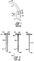
- FIG. 1 there is shown one of the suture anchors disclosed in the above-identified U.S. Patent Application Serial No. 051,367.
- This suture anchor identified generally by the numeral 105, comprises a coupling member 110 and a barb 115.
- Coupling member 110 comprises a piece of 6A14V titanium alloy having a first end surface 120 and a second end surface 125.
- First end surface 120 is disposed at an angle of approximately 30 degrees to the coupling member's longitudinal axis
- second end surface 125 is disposed at a right angle to the coupling member's longitudinal axis, as shown.
- Coupling member 110 has a blind hole 130 opening on second end surface 125, and a bore 135 extending at an angle between the coupling member's side wall and its bottom end surface 120, as shown. Bore 135 extends at a right angle to the coupling member's bottom end surface 120.
- a suture anchor adapted to anchor a No.
- coupling member 110 preferably has a length of approximately 4.06 mm (0.160 inch) and a diameter of approximately 1.35 mm (0.053 inch), blind hole 130 has a depth of approximately 1.78 mm (0.070 inch) and a diameter of approximately 0.711 mm (0.028 inch), and bore 135 has a diameter of approximately 0.711 (0.028 inch).
- Barb 115 comprises a curved length of nickel titanium alloy having a first end 140 and a second end 145.
- barb 115 preferably has a diameter of approximately 0.660 mm(0.026 inch) and, in its unrestrained state, comprises an arc of approximately 135 degrees or a loop approximately 6.35 mm (0.250 inch) in diameter (when measured to the inside of the loop).
- Barb 115 is attached to the coupling member by fitting the barb's first end 140 into the coupling member's blind hole 130, whereby the barb's second end 145 extends upward and outward from the coupling member.
- Coupling member 110 is then crimped inward at one or more points as shown at 150 to lock barb 115 to the coupling member.
- Barb 115 is made of such a nickel titanium alloy that it is capable of being elastically deformed to a substantially straight length when desired (i.e., so that the barb's second end 145 is aligned with its first end 140, as well as with the opposite ends of the coupling member).
- barb 115 may be made out of binary nitinol such as that sold by Furukawa of Japan and Raychem Corporation of Menlo Park, California, or it might be made out of ternary nitinol such as that sold by Raychem Corporation and described in U.S Patent No. 4,505,767 (Quinn).
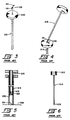
- FIG. 2 there is shown one of the suture anchor installation tools disclosed in the above-identified U.S. Patent Application Serial No. 051,367.
- This suture anchor installation tool identified generally by the numeral 205, may be used to deploy the suture anchor shown in Fig. 1.
- Installation tool 205 comprises a hollow sheath or cannula 210, a hollow loader or inserter 215 and a solid (or hollow) plunger 220.
- Hollow sheath 210 terminates in a flat annular surface 225 at its front end and a flat annular surface 230 at its rear end. Surfaces 225 and 230 are disposed at an angle substantially perpendicular to the longitudinal axis of sheath 210. Sheath 210 has an axial bore 235 extending between its front and rear surfaces 225 and 230. Sheath 210 includes a disk-like finger grip 240 which is affixed to the rear end of the outer sheath member and includes a flat surface 245 which is coplanar with the sheath member's rear surface 230. In the case of an installation tool adapted to deploy a suture anchor for anchoring a No.
- sheath 210 preferably has an outer diameter (i.e., forward of finger grip 240) of approximately 2.11 mm (0.083 inch), an inner diameter of approximately 1.80 mm (0.071 inch), and a length of approximately 102 mm (4.0 inches).
- Hollow loader 215 terminates in a flat annular surface 250 at its front end and a flat annular surface 255 at its rear end. Surfaces 250 and 255 are disposed at an angle substantially perpendicular to the longitudinal axis of loader 215.
- Loader 215 has an axial bore 260 extending between its front surface 250 and its rear surface 255.
- Loader 215 includes a disk-like finger grip 265 which is attached to the rear end of the loader member and includes a flat surface 270 that is coplanar with the loader's rear surface 255.
- Loader 215 is sized to that it will make a close sliding fit within bore 235 of sheath 210, as will hereinafter be described in further detail, and also so that its leading tip 250 will not protrude from the front end of sheath member 210 when the loader is inserted into the sheath's axial bore 235 and the loader's finger grip 265 is in engagement with the sheath's rear surface 230, as will hereinafter be described in further detail.
- an installation tool adapted to deploy a suture anchor for anchoring a No.
- loader 215 preferably has an outer diameter (i.e., forward of finger grip 265) of approximately 1.65 mm (0.065 inch), an inner diameter of approximately 1.12 mm (0.047 inch) and a length of approximately 105 mm (4.13 inches).
- Plunger 220 includes a solid (or hollow) body section 275 and a head section 280.
- Body section 275 has a round cross-section and terminates in a front surface 285.
- Plunger 220 is sized so that its body section 275 will make a close sliding fit within bore 260 of loader 215 and also so that its leading tip 285 will protrude from the front end of the loader member a short distance when the plunger's head section 280 is in engagement with the loader member's rear surface 270, as will hereinafter be described in further detail.
- plunger 220 preferably has a diameter of approximately 0.047 inch forward of head section 280, and a length of approximately 4.32 inches, as will hereinafter be described in further detail.
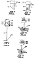
- Installation tool 205 is intended to be utilized as follows. Looking next at Fig. 3, suture anchor 105 is loaded into the top end of sheath member 210 so that the suture anchor's coupling member 110 resides inside the sheath's axial bore 235 and the suture anchor's barb 115 extends above finger grip 240 of the sheath member. Looking next at Fig. 4, the front end 250 of loader 215 is then slipped over the free end of the suture anchor's barb 115 so that the free end of the barb extends into the loader member's axial bore 260.
- loader member 215 is (a) forced into coaxial alignment with outer sheath member 210, thereby straightening out barb 115 in the process, and (b) pushed into the interior of sheath member 210, carrying the suture anchor downward within the sheath member as it goes.
- the sheath's bottom surface 225 is rested against a stationary surface 305 (see Fig. 5) while suture anchor loader 215 is brought downward into direct contact with the suture anchor's rear surface 125.
- Sheath member 210 and loader member 215 are carefully sized relative to one another (and relative to suture anchor 105) so that when the loader member's finger grip 265 is thereafter brought into contact with the sheath member's top surface 245, the suture anchor will protrude slightly from the bottom end of the sheath member, as shown in Fig. 6. More specifically, as seen in Figs. 7 and 8, sheath member 210 and loader member 215 are sized relative to one another (and relative to suture anchor 105) so that both ends of the suture anchor's diagonal bore 135 will be exposed to view when the loader member's finger grip 265 is brought into contact with the sheath member's top surface 245.
- a conventional suture 405 may then be easily attached to the suture anchor by passing the suture through the anchor's diagonal bore 135 and tying a knot 410 at the end of the suture which can then bear against the bottom end 120 of the suture anchor's coupling member, as shown in Figs. 7 and 8.
- plunger member 220 may then be inserted into the loader member's internal bore 260 (see Fig. 9) and pressed downward until its bottom tip 285 contacts the suture anchor barb contained in the loader member's bore 260.
- the head section 280 of the plunger member will remain slightly above finger grip 265 of loader member 215 when the plunger member's tip 285 engages barb 115 of suture anchor 105.
- the tip of the installation tool is inserted into a hole 505 formed in a bone 510 until the suture anchor rests on the bone surface 515 (see Fig. 10), and then head section 280 of plunger member 220 is held stationary while finger grip 240 of sheath member 210 is pulled upward so that the loader's flat surface 270 engages the underside or the plunger's head section 280, thereby ejecting the suture anchor 105 (and its attached suture 405) out of the installation tool and into the bone, as shown in rigs. 10 and 11.
- a hole slightly larger in size than the combined diameters of the outer sheath member 210 and the suture 405 must be drilled in the bone.
- a suture anchor for anchoring a No. 0 suture where the suture anchor's coupling member 110 has a diameter of approximately 1.35 mm (0.53 inch), suture 405 has a diameter of approximately 0.356 mm (0.014 inch), and outer sheath 210 has a diameter of approximately 2.11 mm (0.083 inch), a hole approximately 2.49 mm (0.098 inch) in diameter must be drilled in the bone.
- suture anchor's coupling member 110 has a diameter of approximately 1.55 mm (0.061 inch)
- suture 405 has a diameter of approximately 0.51 mm (0.020 inch)
- outer sheath 210 has a diameter of approximately 2.41 mm (0.095 inch)
- a hole approximately 2.95 mm (0.116 inch) in diameter must be drilled in the bone.
- the suture anchor for anchoring a No,0 suture has a coupling member diameter of approximately 1.35 mm (0.053 inch), yet it requires a drilled hole of approximately 2.49 mm (0.098 inch) to accommodate the suture anchor when it is set by installation tool 205. Therefore, the suture anchor's barb must essentially take up the difference between the 1.35 mm (0.053 inch) coupling member and the 2.49 mm (0.098 inch) hole when the suture anchor is set in the hole.
- the barb must expand approximately 1.14 mm (0.045 inch) for the suture anchor used to anchor a No. 0 suture.
- the suture anchor for anchoring a No. 2 suture has a coupling member diameter of approximately 1.55 mm (0.061 inch), yet it requires a drilled hole of approximately 2.95 mm (0.116 inch) to accommodate the suture anchor when it is set by installation tool 205. Therefore, the barb must essentially take up the difference between the 1.55 mm (0.061 inch) coupling member and the 2.95 mm (0.116 inch) pole when the suture anchor is set in the hole. Thus, the barb must expand approximately 1.40 mm (0.055 inch) for the suture anchor used to anchor a No. 2 suture.
- the outer sheath 210 and loader member 215 can be preloaded with the suture anchor (in the manner shown in Figs. 5 and 6) but, if it is then left for a substantial amount of time between loading and use, the barb can lose its resiliency and relax over time, so that when the suture anchor is thereafter used, its barb may not contact the bone wall with the same force that it would have if the suture anchor had been used immediately after loading the suture anchor into sheath 210 and loader 215. Accordingly, preloading accompanied by delayed use can possibly lead to inconsistent and unsatisfactory anchoring of the bone anchor in the bone.
- a multiple part suture anchor installation tool for deploying a suture anchor of the type comprising a coupling member having an end surface, at least one barb, the or each barb having a first end and a second end, being curved in its normal unstressed state, being capable of being elastically deformed to a substantially straight configuration and being attached to the coupling member so that the second end of the barb is substantially displaced from the coupling member when the barb is in its normal unstressed state but is capable of being aligned with the coupling member when the barb is deformed to a substantially straight length, and attachment means for attaching one end of a suture to the suture anchor.
- a suturing device which includes an elongate, suture-like coupling member having at least one barb at each of its ends. Tanner also discloses a needle comprising a shaft having pointed end including a notch for receiving one of the barbs located at one or the other end of the coupling member. The needle further comprises a channel extending the full longitudinal length of the needle. In use, one of the barbs is hooked into the notch such that the coupling member rests in the channel. Thereafter, axial drive is transmitted from the needle to the portion of the suturing device whereat the barb joins the coupling member in order to deploy the barbed end of the suturing device in one of the two pieces of tissue to be joined. The process then is repeated for the barb at the other end of the coupling member in order to achieve the desired attachment.
- U.S. Patent No. 4,705, 040 to Mueller and U.S. Patent No. 4,699,473 to Richards each show a two part insertion tool for the deployment of an anchoring device including a rigid cross member normally disposed at a right angle to a filament attached to the cross member substantially midway between its ends.
- an additional filament is attached to one end of the cross member.
- the installation tool in both cases includes a hollow outer shaft having a longitudinal slot extending inwardly from its distal end, and a plunger member adapted for telescopic movement within the outer shaft.
- the cross member is inserted wholly into the outer shaft with the filament(s) extending outwardly through the slot whereupon they are drawn toward the proximal end of the outer shaft.
- the distal end of the outer shaft then is positioned adjacent to the desired location for the cross member, and the plunger is moved distally within the outer shaft to expel the cross member from the distal end of the outer shaft. Finally, tension is applied to the filament attached to the middle of the cross member. This tension, combined with the resilient tendency of the cross member to return to is normal disposition relative to the filament, shifts the orientation of the coupling member from axial alignment with the lumen of the outer shaft to an orientation at a right angle to the filament.
- the principal object of the present invention is to provide a novel suture anchor installation tool which improves upon the three-element installation tool of the above identified U.S. Patent Application Serial No. 051,367.
- Another object of the present invention is to provide a suture anchor installation tool which minimizes the gap between the body of the suture anchor and the bone hole, whereby less expansion of the barb will be required to fix the suture anchor in the bone and a tighter attachment of the suture anchor to the bone will result.
- Still another object of the present invention is to provide a suture anchor installation tool in which the suture anchor's barb is not deformed to a straight length when it is loaded into the installation tool, whereby the holding power of the suture anchor will not deteriorate when the suture anchor is stored for a long period of time in the installation tool prior to use.
- Still another object of the present invention is to provide a novel method for deploying a suture anchor in bone.
- a novel suture anchor installation tool which comprises an elongated member having a first end and a second end and a slot extending from the first end towards the second end, the slot being sized to snugly accommodate the suture anchor's barb therein, whereby the suture anchor may be attached to the elongated member at the first end of the elongated member by fitting the barb into the slot so that the barb extends upward and outward from the first end of the elongated member, through the slot, with the flat end of the suture anchor's coupling member engaging the first end of the installation tool.
- the suture is first attached to the suture anchor, and then the suture anchor is attached to the installation tool in the foregoing manner. Then the first end of the elongated member is inserted into the predrilled hole in the bone, forcing the suture anchor in ahead of it. As the suture anchor is pressed into the bone, its barb engages the side wall of the bone and is forced to retract backwards into the elongated member's slot, so that the barb extends somewhat parallel to the elongated member.
- the elongated member When the suture anchor bottoms out in the bone hole, the elongated member is then withdrawn, whereupon the barb's engagement with the bone wall causes the suture anchor to separate from the elongated member, leaving the suture anchor (and its attached suture) anchored securely in the bone.
- the invention therefore includes a suture anchor installation tool for deploying a suture anchor as set out in claim 1.
- FIGs. 12 and 13 there is shown a suture anchor installation tool 605 which constitutes the preferred embodiment of the present invention.
- Installation tool 605 comprises a hollow cannula 610 having a distal end 615 terminating in a flat end surface 620 and a rear end 625 terminating in a flat disk or knob 630.
- a longitudinally-extending slot 635 is formed in the side wall of cannula 610. Slot 635 begins at the cannula's distal end surface 620 and terminates in a rear surface 640.
- Installation tool 605 is adapted to be used to install a suture anchor such as the suture anchor 105 previously described, and to this end it is important that installation tool 605 be dimensioned in accordance with the dimensions of the actual suture anchor being deployed by the tool. Specifically, it is important that suture anchor installation tool 605 be sized so that (a) its cannula 610 has an outer diameter smaller than, equal to or just slightly larger than the outer diameter of the suture anchor's coupling member 110 so that the smallest possible hole may be formed in the bone which is to receive the bone anchor, (b) its cannula 610 has an internal diameter smaller than the outer diameter of the suture anchor's coupling member 110, so that the coupling member will not be able to slip inside the cannula, (c) its slot 635 has a width equal to or just slightly larger than the diameter of the suture anchor's barb 115, so that the barb will fit snugly between the walls of cannula 610 which define its slot 635, as will hereinafter be described
- cannula 610 preferably has an inner diameter of approximately 0.050 inch and an outer diameter of approximately 0.058 inch
- slot 635 has a length (i.e., when measured from flat end surface 620 to slot rear surface 640) of approximately 9,39 mm (0.370 inch) and a width of approximately 0,78 mm (0.031 inch).
- suture anchor 105 is to be used to anchor a No. 2 suture
- the same installation tool may be used, since the suture anchor used in conjunction with a No.
- suture anchor installation tool 605 has an overall length, when measured from distal end 620 to the rear of disk 630, of approximately 114,3 mm (4.0 inches).
- a suture is first attached to suture anchor 105, then the suture anchor is attached to the distal end of installation tool 605, and then the suture anchor is deployed into a hole formed in the bone using installation tool 605.
- the suture is first attached to the suture anchor in the manner shown in Fig. 14A, i.e., by passing the suture through the suture anchor's bore 135 and then tying a knot 410 at the bottom end of the suture so that the knot seats against face 120 of suture anchor 105.
- Suture anchor 105 is then attached to the distal end of the installation tool by fitting the suture anchor's barb 115 into the installation tool's slot 635 and pressing the top surface 125 of the suture anchor flush against the installation tool's bottom surface 620.
- coupling member 110 of the suture anchor is unable to enter the interior of cannula 610, and barb 115 will make a snug fit in cannula slot 635, the fit being snug enough to hold the suture anchor attached to the bottom end of the cannula.
- the suture anchor is then ready to be deployed in a hole 505 formed in a bone 510 (see Fig. 16).
- the hole formed in the bone is carefully sized according to the dimensions of the suture and suture anchor being deployed in the bone.
- the hole formed in bone 510 is sized so as to have a diameter of approximately 1,82 mm (0.072 inch) and a depth of approximately 17,78 mm (0.70 inches).
- the suture anchor is then deployed in the bone hole by pressing the distal end of the cannula down into the predrilled hole 505 in bone 510 until the assembly bottoms out on bone surface 515.
- the suture anchor's barb 115 engages the side wall of the bone, forcing the barb to retract inwards, into the cannula slot, so that the suture anchor installation tool (and the suture anchor and the suture carried by the suture anchor) can enter bone hole 505.
- the engagement of the suture anchor's barb with the bone wall causes the suture anchor to separate from the cannula, leaving the suture anchor (and its attached suture) securely anchored in the bone.
- a hole only slightly wider than the combined diameters of the cannula 610 and the suture 405 may be drilled in the bone.
- a hole only approximately 1,82 mm (0.072 inch) in diameter must be drilled in the bone;
- a No. 2 suture is to be attached to the bone using an appropriately sized bone anchor 105 and an appropriately sized installation tool 605, a hole only approximately 2,18 mm (0.086 inch) in diameter must be drilled in the bone.
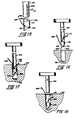
- installation tool 605 could be formed out of a substantially solid rod rather than a hollow cannula; in this case, installation tool 605A (see Fig. 19) would comprise a solid rod 610A having a slot 635A formed therein. Rod 610A would have the same outer diameter as the cannula 610 previously described. It will be appreciated that installation tool 605A functions in exactly the same manner, and provides substantially the same advantages, as the installation tool 605 previously described.
- FIG. 20 a modified form of installation tool 705 is shown in Figure 20.
- Installation tool 705 is identical to the installation tool 605 previously described, except that the cannula 710 is sized to accept a portion of the coupling member 110 of the suture anchor 105. More specifically, cannula 710 has a slightly larger outer diameter than the cannula 610 previously described, and it includes a counterbore 745 which opens on the cannula's distal surface 720 and which terminates in an internal shoulder 750.
- Shoulder 750 is positioned at a sufficient depth to allow a portion of the suture anchor's coupling member to be received within the cannula's counterbore 745, with the suture anchor's suture-receiving hole still being completely exposed.
- counterbore 745 and shoulder 750 are created by relieving a thick-walled hypodermic tubing to the desired depth.
- cannula 710 preferably has an inner diameter of approximately 1,37 mm (0.054 inch) and an outer diameter of approximately 1,65 mm (0.065 inch)
- slot 735 has a length (i.e., when measured from flat end surface 720 to the slot rear surface 740) of approximately 9,39 mm (0.370 inch) and a width of 0,78 mm (0.031 inch).
- the cavity which accepts the suture anchor has a length (i.e., when measured from flat end surface 720 to stop 750) of approximately 1,52 mm (0.060 inch).
- cannula 710 preferably has an inner diameter of approximately 1,57 mm (0.062 inches) and an outer diameter of approximately 1,82 mm (0.072 inches)
- slot 735 has a length (i.e., when measured from flat end surface 720 to the slot rear surface 740) of approximately 9,39 mm (0.370 inch) and a width of approximately 0.031 inch.
- the cavity which accepts the suture anchor has a length (i.e., when measured from flat end surface 710 to stop 750) of approximately 1,52 mm (0.060 inch).
- the suture anchor installation tool 705 has an overall length, when measured from distal end 720 to the rear of its top end, of approximately 114,3 mm (4.0 inches).
- installation tool 705A which is adapted to receive a portion of the suture anchor's coupling member in the installation tool's distal end.
- installation tool 705A comprises a solid rod 710A having a slot 735A and a blind hole 745A formed therein.
- blind hole 745A is sized to have a depth such that the suture anchor's suture-receiving hole will remain exposed when the coupling member is attached to the installation tool.
- Rod 710A is intended to have the same outer diameter as the cannula 710 previously described.
- FIG. 21B there is shown yet another form of the invention.
- Installation tool 705B is identical to the installation tool 705 previously described, except that the hollow cannula 710B has an internal diameter as large as the diameter of the previously described counterbore 745, in order that the entire suture anchor will be received inside cannula 710A.
- No counterbore 745 or shoulder 750 is provided; instead, the cannula is crimped inward at 755B at one or more locations to form a stop for engaging the upper surface of the coupling member.
- crimps 755B are placed sufficiently far up along cannula 710B so that the entire length of the suture anchor's coupling member may be received within the cannula; in this case, a slot 736B is formed in the cannula, diametrically opposed from the barb-receiving slot 735B, to allow suture 405B to pass through the cannula's side wall.
- Cannula 710B is intended to have the same outer diameter as the cannula 710 previously described.
- the installation tools shown in Figs. 20, 21A and 21B all have an outer diameter which is greater than the outer diameter of the installation tools shown in Figs. 12 and 19; nonetheless , smaller bone holes can still be used when using the installation tools of Figs. 20, 21A and 21B than when using the three-element installation tool of Fig. 2. More specifically, a summary table of the sizing for the tools of Figs. 20, 21A and 21B is given below: TABLE 3 Suture Sizes No. O No.
- installation tools 605, 605A, 705, 705A and/or 705B could be provided with a plurality of slots 635, 635A, 735, 735A and 735B, respectively, for situations where the installation tool is to be used to deploy a suture anchor 105B of the sort having two or more barbs 115B.
- Fig. 22 illustrates a suture anchor installation tool 605B which may be used to install a suture anchor 105B (having three barbs 115B) in bone.
- Yet another modification relates to the method of utilizing the present invention. More specifically, while in all of the foregoing embodiments it was described that the suture is attached to the suture anchor prior to attaching the suture anchor to the installation tool, it is also anticipated that the suture could be attached to the suture anchor after the suture anchor is attached to the installation tool.
- Drill 805 for forming the hole 505 in bone 510 which is to receive the suture anchor.
- Drill 805 comprises a conventional helical drill thread 810 at its distal end. Thread 810 terminates in an inclined frustoconical shoulder 815 which serves as a stop to prevent the drill from penetrating too far into the bone. Shoulder 815 also serves to chamfer bone 510 at 515 as shown so as to minimize chafing of the suture about the top of hole 505.
- suture anchor's coupling member 110 could be formed out of a material other than 6AL4V titanium alloy, and barb 115 could be formed out of a material other than nickel titanium alloy.
- coupling member 110 could be formed out of titanium and its alloys, ceramics, plastics, stainless steel and other suitable bio-compatible materials, and barb 115 could be formed out of titanium and its alloys, and stainless steel.
- a novel suture anchor installation tool is provided which minimizes the gap between the body of the suture anchor and the bone hole, whereby less expansion of the barb will be required to fix the suture anchor in the bone and a tighter attachment of the suture anchor to the bone will result.
- a novel suture anchor installation tool in which the suture anchor's barb is not deformed to a straight length when it is loaded in the installation tool, whereby the holding power of the suture anchor will not deteriorate when the suture anchor is stored for a long time in the installation tool prior to use.
Abstract
Description
- This invention relates to an installation tool for deploying a suture anchor of the type adapted to anchor one end of a piece of conventional suture in bone.
- In co-pending U.S. Patent Application Serial No. 051,367, filed 5/18/87 by Roland F. Gatturna et al for "Suture Anchor" (which corresponds to International Publication No. WO 88/09157 of 1 December 1988), there is disclosed a variety of suture anchors of the sort adapted to anchor one end of a piece of conventional suture in bone, and there is disclosed several suture anchor installation tools for deploying such suture anchors in bone.
- The specification and drawings of the above-identified U.S. Patent Application Serial No. 051,367 is hereby incorporated by reference into the present patent application.
- Looking now at Fig. 1, there is shown one of the suture anchors disclosed in the above-identified U.S. Patent Application Serial No. 051,367. This suture anchor, identified generally by the
numeral 105, comprises acoupling member 110 and abarb 115. -
Coupling member 110 comprises a piece of 6A14V titanium alloy having afirst end surface 120 and asecond end surface 125.First end surface 120 is disposed at an angle of approximately 30 degrees to the coupling member's longitudinal axis, andsecond end surface 125 is disposed at a right angle to the coupling member's longitudinal axis, as shown.Coupling member 110 has ablind hole 130 opening onsecond end surface 125, and abore 135 extending at an angle between the coupling member's side wall and itsbottom end surface 120, as shown. Bore 135 extends at a right angle to the coupling member'sbottom end surface 120. In the case of a suture anchor adapted to anchor a No. 0 suture (i.e., a suture having a diameter of approximately 0.356 mm [0.014 inch]),coupling member 110 preferably has a length of approximately 4.06 mm (0.160 inch) and a diameter of approximately 1.35 mm (0.053 inch),blind hole 130 has a depth of approximately 1.78 mm (0.070 inch) and a diameter of approximately 0.711 mm (0.028 inch), andbore 135 has a diameter of approximately 0.711 (0.028 inch). -
Barb 115 comprises a curved length of nickel titanium alloy having afirst end 140 and asecond end 145. In the case of a suture anchor adapted to anchor a No. 0 suture,barb 115 preferably has a diameter of approximately 0.660 mm(0.026 inch) and, in its unrestrained state, comprises an arc of approximately 135 degrees or a loop approximately 6.35 mm (0.250 inch) in diameter (when measured to the inside of the loop). Barb 115 is attached to the coupling member by fitting the barb'sfirst end 140 into the coupling member'sblind hole 130, whereby the barb'ssecond end 145 extends upward and outward from the coupling member.Coupling member 110 is then crimped inward at one or more points as shown at 150 to lockbarb 115 to the coupling member.Barb 115 is made of such a nickel titanium alloy that it is capable of being elastically deformed to a substantially straight length when desired (i.e., so that the barb'ssecond end 145 is aligned with itsfirst end 140, as well as with the opposite ends of the coupling member). By way of example,barb 115 may be made out of binary nitinol such as that sold by Furukawa of Japan and Raychem Corporation of Menlo Park, California, or it might be made out of ternary nitinol such as that sold by Raychem Corporation and described in U.S Patent No. 4,505,767 (Quinn). - Looking next at Fig. 2, there is shown one of the suture anchor installation tools disclosed in the above-identified U.S. Patent Application Serial No. 051,367. This suture anchor installation tool, identified generally by the
numeral 205, may be used to deploy the suture anchor shown in Fig. 1.Installation tool 205 comprises a hollow sheath orcannula 210, a hollow loader orinserter 215 and a solid (or hollow)plunger 220. -
Hollow sheath 210 terminates in a flatannular surface 225 at its front end and a flatannular surface 230 at its rear end.Surfaces sheath 210. Sheath 210 has anaxial bore 235 extending between its front andrear surfaces like finger grip 240 which is affixed to the rear end of the outer sheath member and includes aflat surface 245 which is coplanar with the sheath member'srear surface 230. In the case of an installation tool adapted to deploy a suture anchor for anchoring a No. 0 suture,sheath 210 preferably has an outer diameter (i.e., forward of finger grip 240) of approximately 2.11 mm (0.083 inch), an inner diameter of approximately 1.80 mm (0.071 inch), and a length of approximately 102 mm (4.0 inches). -
Hollow loader 215 terminates in a flatannular surface 250 at its front end and a flatannular surface 255 at its rear end.Surfaces loader 215. Loader 215 has anaxial bore 260 extending between itsfront surface 250 and itsrear surface 255. Loader 215 includes a disk-like finger grip 265 which is attached to the rear end of the loader member and includes aflat surface 270 that is coplanar with the loader'srear surface 255. Loader 215 is sized to that it will make a close sliding fit withinbore 235 ofsheath 210, as will hereinafter be described in further detail, and also so that its leadingtip 250 will not protrude from the front end ofsheath member 210 when the loader is inserted into the sheath'saxial bore 235 and the loader'sfinger grip 265 is in engagement with the sheath'srear surface 230, as will hereinafter be described in further detail. In the case of an installation tool adapted to deploy a suture anchor for anchoring a No. 0 suture,loader 215 preferably has an outer diameter (i.e., forward of finger grip 265) of approximately 1.65 mm (0.065 inch), an inner diameter of approximately 1.12 mm (0.047 inch) and a length of approximately 105 mm (4.13 inches). -
Plunger 220 includes a solid (or hollow)body section 275 and ahead section 280.Body section 275 has a round cross-section and terminates in afront surface 285. Plunger 220 is sized so that itsbody section 275 will make a close sliding fit withinbore 260 ofloader 215 and also so that its leadingtip 285 will protrude from the front end of the loader member a short distance when the plunger'shead section 280 is in engagement with the loader member'srear surface 270, as will hereinafter be described in further detail. In the case of an installation tool adapted to deploy a suture anchor for anchoring a No. 0 suture,plunger 220 preferably has a diameter of approximately 0.047 inch forward ofhead section 280, and a length of approximately 4.32 inches, as will hereinafter be described in further detail. -
Installation tool 205 is intended to be utilized as follows. Looking next at Fig. 3,suture anchor 105 is loaded into the top end ofsheath member 210 so that the suture anchor'scoupling member 110 resides inside the sheath'saxial bore 235 and the suture anchor'sbarb 115 extends abovefinger grip 240 of the sheath member. Looking next at Fig. 4, thefront end 250 ofloader 215 is then slipped over the free end of the suture anchor'sbarb 115 so that the free end of the barb extends into the loader member'saxial bore 260. Thenloader member 215 is (a) forced into coaxial alignment withouter sheath member 210, thereby straightening outbarb 115 in the process, and (b) pushed into the interior ofsheath member 210, carrying the suture anchor downward within the sheath member as it goes. In order to assure thatbarb 115 ofsuture anchor 105 is contained completely withinloader 215 such that sutureanchor loader surface 250 contactssuture anchor surface 125, the sheath'sbottom surface 225 is rested against a stationary surface 305 (see Fig. 5) whilesuture anchor loader 215 is brought downward into direct contact with the suture anchor'srear surface 125. Sheathmember 210 andloader member 215 are carefully sized relative to one another (and relative to suture anchor 105) so that when the loader member'sfinger grip 265 is thereafter brought into contact with the sheath member'stop surface 245, the suture anchor will protrude slightly from the bottom end of the sheath member, as shown in Fig. 6. More specifically, as seen in Figs. 7 and 8,sheath member 210 andloader member 215 are sized relative to one another (and relative to suture anchor 105) so that both ends of the suture anchor'sdiagonal bore 135 will be exposed to view when the loader member'sfinger grip 265 is brought into contact with the sheath member'stop surface 245. With the suture anchor so held by the installation tool, aconventional suture 405 may then be easily attached to the suture anchor by passing the suture through the anchor'sdiagonal bore 135 and tying aknot 410 at the end of the suture which can then bear against thebottom end 120 of the suture anchor's coupling member, as shown in Figs. 7 and 8. - Once the suture has been attached to the suture anchor in the foregoing manner,
plunger member 220 may then be inserted into the loader member's internal bore 260 (see Fig. 9) and pressed downward until itsbottom tip 285 contacts the suture anchor barb contained in the loader member's bore 260. By appropriately sizing the respective members involved, thehead section 280 of the plunger member will remain slightly abovefinger grip 265 ofloader member 215 when the plunger member'stip 285 engagesbarb 115 ofsuture anchor 105. - Thereafter, when the installation tool is actually to deploy the suture anchor (and its attached suture) into bone, the tip of the installation tool is inserted into a
hole 505 formed in abone 510 until the suture anchor rests on the bone surface 515 (see Fig. 10), and thenhead section 280 ofplunger member 220 is held stationary whilefinger grip 240 ofsheath member 210 is pulled upward so that the loader'sflat surface 270 engages the underside or the plunger'shead section 280, thereby ejecting the suture anchor 105 (and its attached suture 405) out of the installation tool and into the bone, as shown in rigs. 10 and 11. - Complete details regarding the construction and use of
suture anchor 105 andinstallation tool 205 are provided in the above-identified U.S. Patent Application Serial No. 051,367, which is incorporated herein by reference; the foregoing description is provided merely for convenient reference in understanding the present invention. - With the three-
element installation tool 205 described above, a hole slightly larger in size than the combined diameters of theouter sheath member 210 and thesuture 405 must be drilled in the bone. For example, with a suture anchor for anchoring a No. 0 suture, where the suture anchor'scoupling member 110 has a diameter of approximately 1.35 mm (0.53 inch),suture 405 has a diameter of approximately 0.356 mm (0.014 inch), andouter sheath 210 has a diameter of approximately 2.11 mm (0.083 inch), a hole approximately 2.49 mm (0.098 inch) in diameter must be drilled in the bone. In the case of a suture anchor for anchoring a No. 2 suture, where the suture anchor'scoupling member 110 has a diameter of approximately 1.55 mm (0.061 inch),suture 405 has a diameter of approximately 0.51 mm (0.020 inch),andouter sheath 210 has a diameter of approximately 2.41 mm (0.095 inch), a hole approximately 2.95 mm (0.116 inch) in diameter must be drilled in the bone. - A summary table of such sizing is given below:
Table 1 Suture Size: No. 0 No. 2 mm inch inch mm Suture Anchor Dia. 1.35 0.053 0.061 1.55 Sheath Diameter 2.11 0.083 0.095 2.41 Suture Diameter 0.356 0.014 0.020 0.508 ----- ----- Sheath + Suture Dia. 2.46 0.097 0.115 2.92 Drill Diameter 2.49 0.098 0.116 2.95 (Drill hole) - (Suture Anchor) 1.14 0.045 0.055 1.40 - Unfortunately, while the three-
element installation tool 205 described above is known to work, it is also believed to suffer from a number of disadvantages. - For one thing, it will be seen from Table 1 above that the three-
element installation tool 205 takes up a substantial amount of room in the bone hole relative to the diameter of the suture anchor. More specifically, as seen in Table 1 above, the suture anchor for anchoring a No,0 suture has a coupling member diameter of approximately 1.35 mm (0.053 inch), yet it requires a drilled hole of approximately 2.49 mm (0.098 inch) to accommodate the suture anchor when it is set byinstallation tool 205. Therefore, the suture anchor's barb must essentially take up the difference between the 1.35 mm (0.053 inch) coupling member and the 2.49 mm (0.098 inch) hole when the suture anchor is set in the hole. Thus, the barb must expand approximately 1.14 mm (0.045 inch) for the suture anchor used to anchor a No. 0 suture. Similarly, as seen in Table 1 above, the suture anchor for anchoring a No. 2 suture has a coupling member diameter of approximately 1.55 mm (0.061 inch), yet it requires a drilled hole of approximately 2.95 mm (0.116 inch) to accommodate the suture anchor when it is set byinstallation tool 205. Therefore, the barb must essentially take up the difference between the 1.55 mm (0.061 inch) coupling member and the 2.95 mm (0.116 inch) pole when the suture anchor is set in the hole. Thus, the barb must expand approximately 1.40 mm (0.055 inch) for the suture anchor used to anchor a No. 2 suture. Inasmuch as the barb loses force as it returns closer and closer to its original curved shape from its constrained straight shape (e.g. much like a spring),the larger the difference existing between the bone hole diameter and the suture anchor body, the smaller the force applied to the side wall of the bone by the suture anchor's barb when the suture anchor is set in the bone, and hence the weaker the attachment of the suture anchor to the bone. Accordingly, a fit such as that mandated by the use of the three-element installation tool 205 could possibly lead to inconsistent anchoring of the suture in the bone. - Another disadvantage of the three-
element installation tool 205 described above is that theouter sheath 210 andloader member 215 can be preloaded with the suture anchor (in the manner shown in Figs. 5 and 6) but, if it is then left for a substantial amount of time between loading and use, the barb can lose its resiliency and relax over time, so that when the suture anchor is thereafter used, its barb may not contact the bone wall with the same force that it would have if the suture anchor had been used immediately after loading the suture anchor intosheath 210 andloader 215. Accordingly, preloading accompanied by delayed use can possibly lead to inconsistent and unsatisfactory anchoring of the bone anchor in the bone. - It therefore will be understood that the subject matter of International Publication No. W0 88/09157 includes, and makes known within the terms of Article 54(3), the following features:
A multiple part suture anchor installation tool for deploying a suture anchor of the type comprising a coupling member having an end surface, at least one barb, the or each barb having a first end and a second end, being curved in its normal unstressed state, being capable of being elastically deformed to a substantially straight configuration and being attached to the coupling member so that the second end of the barb is substantially displaced from the coupling member when the barb is in its normal unstressed state but is capable of being aligned with the coupling member when the barb is deformed to a substantially straight length, and attachment means for attaching one end of a suture to the suture anchor. - In U.S. Patent No. 3,716,058 to Tanner a suturing device is shown which includes an elongate, suture-like coupling member having at least one barb at each of its ends. Tanner also discloses a needle comprising a shaft having pointed end including a notch for receiving one of the barbs located at one or the other end of the coupling member. The needle further comprises a channel extending the full longitudinal length of the needle. In use, one of the barbs is hooked into the notch such that the coupling member rests in the channel. Thereafter, axial drive is transmitted from the needle to the portion of the suturing device whereat the barb joins the coupling member in order to deploy the barbed end of the suturing device in one of the two pieces of tissue to be joined. The process then is repeated for the barb at the other end of the coupling member in order to achieve the desired attachment.
- U.S. Patent No. 4,705, 040 to Mueller and U.S. Patent No. 4,699,473 to Richards each show a two part insertion tool for the deployment of an anchoring device including a rigid cross member normally disposed at a right angle to a filament attached to the cross member substantially midway between its ends. In the Mueller reference, an additional filament is attached to one end of the cross member. The installation tool in both cases includes a hollow outer shaft having a longitudinal slot extending inwardly from its distal end, and a plunger member adapted for telescopic movement within the outer shaft. In operation the cross member is inserted wholly into the outer shaft with the filament(s) extending outwardly through the slot whereupon they are drawn toward the proximal end of the outer shaft. The distal end of the outer shaft then is positioned adjacent to the desired location for the cross member, and the plunger is moved distally within the outer shaft to expel the cross member from the distal end of the outer shaft. Finally, tension is applied to the filament attached to the middle of the cross member. This tension, combined with the resilient tendency of the cross member to return to is normal disposition relative to the filament, shifts the orientation of the coupling member from axial alignment with the lumen of the outer shaft to an orientation at a right angle to the filament.
- Accordingly, the principal object of the present invention is to provide a novel suture anchor installation tool which improves upon the three-element installation tool of the above identified U.S. Patent Application Serial No. 051,367.
- Another object of the present invention is to provide a suture anchor installation tool which minimizes the gap between the body of the suture anchor and the bone hole, whereby less expansion of the barb will be required to fix the suture anchor in the bone and a tighter attachment of the suture anchor to the bone will result.
- Still another object of the present invention is to provide a suture anchor installation tool in which the suture anchor's barb is not deformed to a straight length when it is loaded into the installation tool, whereby the holding power of the suture anchor will not deteriorate when the suture anchor is stored for a long period of time in the installation tool prior to use.
- And still another object of the present invention is to provide a novel method for deploying a suture anchor in bone.
- These and other objects of the present invention are achieved through the use of a novel suture anchor installation tool which comprises an elongated member having a first end and a second end and a slot extending from the first end towards the second end, the slot being sized to snugly accommodate the suture anchor's barb therein, whereby the suture anchor may be attached to the elongated member at the first end of the elongated member by fitting the barb into the slot so that the barb extends upward and outward from the first end of the elongated member, through the slot, with the flat end of the suture anchor's coupling member engaging the first end of the installation tool.
- In use, the suture is first attached to the suture anchor, and then the suture anchor is attached to the installation tool in the foregoing manner. Then the first end of the elongated member is inserted into the predrilled hole in the bone, forcing the suture anchor in ahead of it. As the suture anchor is pressed into the bone, its barb engages the side wall of the bone and is forced to retract backwards into the elongated member's slot, so that the barb extends somewhat parallel to the elongated member. When the suture anchor bottoms out in the bone hole, the elongated member is then withdrawn, whereupon the barb's engagement with the bone wall causes the suture anchor to separate from the elongated member, leaving the suture anchor (and its attached suture) anchored securely in the bone.
- The invention therefore includes a suture anchor installation tool for deploying a suture anchor as set out in claim 1.
- Preferred embodiments of the invention are disclosed in the subclaims.
- Still other objects and features of the present invention will be more fully described or rendered obvious in the following detailed description of the invention, which is to be considered together with the accompanying drawings wherein like numbers refer to like parts and further wherein:
- Fig. 1 is a side view in elevation of a prior art suture anchor disclosed in the above identified U.S. Patent Application Serial No. 051,367;
- Fig. 2 is a side view in elevation, in section, showing a prior art suture anchor installation tool disclosed in U.S. Patent Application Serial No. 051, 367;
- Figs. 3-11 are a series of views showing the suture anchor of Fig. 1 being deployed into a bone hole using the suture anchor installation tool of Fig. 2;
- Fig. 12 is a side view in elevation, partly in section, showing the preferred embodiment of the suture anchor installation tool which constitutes the present invention;
- Fig. 13 is an end view in elevation showing the distal end of the suture anchor installation tool of Fig. 12;
- Fig. 14A is a side view in elevation showing the suture being attached to the suture anchor remote from the installation tool;
- Fig. 14B is a perspective view showing the suture and suture anchor of Fig. 14A, the installation tool of Figs. 12 and 13, and a target bone which is to receive the suture anchor, all in exploded relation to one another;
- Fig. 15 is an enlarged partial perspective view showing the suture anchor of Fig. 1 being loaded onto the distal end of the suture anchor installation tool of Figs. 12 and 13;
- Fig. 16 is a perspective view showing the suture anchor of Fig. 1 being loaded onto the distal end of the suture anchor installation tool of Figs. 12 and 13;
- Fig. 17 is a side view in elevation showing the suture anchor of Fig. 1 and the suture anchor installation tool of Figs. 12 and 13 as the suture anchor is being introduced into a hole formed in bone;
- Fig. 18 is a side view in elevation showing the suture anchor of Fig. 1 remaining in the hole formed in the bone as the suture anchor installation tool is withdrawn;
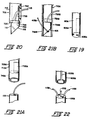
- Fig. 19 is a partial perspective view showing a second embodiment of the suture anchor installation tool;
- Fig. 20 is a partial side elevation showing a third embodiment of the suture anchor installation tool receiving a suture anchor;
- Fig. 21A is a partial perspective view showing a fourth embodiment of the suture anchor installation tool;
- Fig. 21B is a partial side elevation showing a fifth embodiment of the suture anchor installation tool;
- Fig. 22 is a partial perspective view showing a sixth embodiment of the suture anchor installation tool;
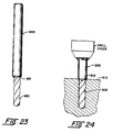
- Fig. 23 is a side view in elevation showing a novel drill for forming the hole in the bone which is to receive the suture anchor; and
- Fig. 24 is a side view in elevation showing the novel drill of Fig. 19 in the process of forming a hole in bone.
- Looking now at Figs. 12 and 13, there is shown a suture
anchor installation tool 605 which constitutes the preferred embodiment of the present invention.Installation tool 605 comprises ahollow cannula 610 having adistal end 615 terminating in aflat end surface 620 and arear end 625 terminating in a flat disk orknob 630. A longitudinally-extendingslot 635 is formed in the side wall ofcannula 610.Slot 635 begins at the cannula'sdistal end surface 620 and terminates in arear surface 640. -
Installation tool 605 is adapted to be used to install a suture anchor such as thesuture anchor 105 previously described, and to this end it is important thatinstallation tool 605 be dimensioned in accordance with the dimensions of the actual suture anchor being deployed by the tool. Specifically, it is important that sutureanchor installation tool 605 be sized so that (a) itscannula 610 has an outer diameter smaller than, equal to or just slightly larger than the outer diameter of the suture anchor'scoupling member 110 so that the smallest possible hole may be formed in the bone which is to receive the bone anchor, (b) itscannula 610 has an internal diameter smaller than the outer diameter of the suture anchor'scoupling member 110, so that the coupling member will not be able to slip inside the cannula, (c) itsslot 635 has a width equal to or just slightly larger than the diameter of the suture anchor'sbarb 115, so that the barb will fit snugly between the walls ofcannula 610 which define itsslot 635, as will hereinafter be described in further detail, and (d) itsslot 635 has a length sufficient to accommodate the suture anchor'sbarb 115 when the barb is bent backwards into the cannula during deployment of the suture anchor, as will hereinafter be described in further detail. - For example, in the case where
suture anchor 105 is to be used to anchor a No. 0 suture, so that the suture anchor has the dimensions identified above,cannula 610 preferably has an inner diameter of approximately 0.050 inch and an outer diameter of approximately 0.058 inch,slot 635 has a length (i.e., when measured fromflat end surface 620 to slot rear surface 640) of approximately 9,39 mm (0.370 inch) and a width of approximately 0,78 mm (0.031 inch). In the case wheresuture anchor 105 is to be used to anchor a No. 2 suture, the same installation tool may be used, since the suture anchor used in conjunction with a No. 2 suture will have the same size barb and an even wider diameter coupling member than the suture anchor used in conjunction with a No. 0 suture. Preferably, sutureanchor installation tool 605 has an overall length, when measured fromdistal end 620 to the rear ofdisk 630, of approximately 114,3 mm (4.0 inches). - In use, a suture is first attached to suture
anchor 105, then the suture anchor is attached to the distal end ofinstallation tool 605, and then the suture anchor is deployed into a hole formed in the bone usinginstallation tool 605. - More specifically, and looking now at Figs. 14A, 14B and 15, the suture is first attached to the suture anchor in the manner shown in Fig. 14A, i.e., by passing the suture through the suture anchor's
bore 135 and then tying aknot 410 at the bottom end of the suture so that the knot seats againstface 120 ofsuture anchor 105.Suture anchor 105 is then attached to the distal end of the installation tool by fitting the suture anchor'sbarb 115 into the installation tool'sslot 635 and pressing thetop surface 125 of the suture anchor flush against the installation tool'sbottom surface 620. It will be appreciated that in view of the relative dimensioning of the suture anchor and the installation tool,coupling member 110 of the suture anchor is unable to enter the interior ofcannula 610, andbarb 115 will make a snug fit incannula slot 635, the fit being snug enough to hold the suture anchor attached to the bottom end of the cannula. - The suture anchor is then ready to be deployed in a
hole 505 formed in a bone 510 (see Fig. 16). It is to be appreciated that the hole formed in the bone is carefully sized according to the dimensions of the suture and suture anchor being deployed in the bone. For example, in the case of a No. 0 suture anchor, the hole formed inbone 510 is sized so as to have a diameter of approximately 1,82 mm (0.072 inch) and a depth of approximately 17,78 mm (0.70 inches). - Looking next at Figs. 17 and 18, the suture anchor is then deployed in the bone hole by pressing the distal end of the cannula down into the
predrilled hole 505 inbone 510 until the assembly bottoms out onbone surface 515. As the distal end of the cannula forces the suture anchor down into the bone, the suture anchor'sbarb 115 engages the side wall of the bone, forcing the barb to retract inwards, into the cannula slot, so that the suture anchor installation tool (and the suture anchor and the suture carried by the suture anchor) can enterbone hole 505. When the bottom of the bone anchor bottoms out in bone hole 505 (see Fig. 18), and the cannula is thereafter withdrawn, the engagement of the suture anchor's barb with the bone wall causes the suture anchor to separate from the cannula, leaving the suture anchor (and its attached suture) securely anchored in the bone. - By using the
installation tool 605 just described, a hole only slightly wider than the combined diameters of thecannula 610 and thesuture 405 may be drilled in the bone. For example, where a No. 0 suture is to be attached to the bone using abone anchor 105 and aninstallation tool 605 of the dimensions indicated above, a hole only approximately 1,82 mm (0.072 inch) in diameter must be drilled in the bone; where a No. 2 suture is to be attached to the bone using an appropriatelysized bone anchor 105 and an appropriatelysized installation tool 605, a hole only approximately 2,18 mm (0.086 inch) in diameter must be drilled in the bone. - A summary table of such sizing is given below:
Table 2 Suture Size: No. 0 No. 2 mm inch inch mm Suture Anchor Dia. 1,34 0.053 0.061 1,54 Cannula Diameter 1,47 0.058 0.058 1,47 Suture Diameter 0,35 0.014 0.020 0,50 ----- ----- Cannula + Suture Dia. 1,70 0.067 0.081 2,05 Drill Diameter 1,82 0.072 0.086 2,18 (Drill hole) - (Suture Anchor) 0,48 0.019 0.025 0,63 - A comparison of Table 2 with Table 1 shows that significantly smaller bone holes may be used when using the installation tool of Figs. 12 and 13 in place of the three-element installation tool of Fig. 2; as a result, less expansion of
barb 115 is required to fix the suture anchor in the bone and a tighter attachment of the suture anchor to the bone results. - It is to be appreciated that certain modifications may be made to the preferred embodiment described above without departing from the scope of the present invention.
- Thus, for example, it is anticipated that
installation tool 605 could be formed out of a substantially solid rod rather than a hollow cannula; in this case,installation tool 605A (see Fig. 19) would comprise a solid rod 610A having aslot 635A formed therein. Rod 610A would have the same outer diameter as thecannula 610 previously described. It will be appreciated thatinstallation tool 605A functions in exactly the same manner, and provides substantially the same advantages, as theinstallation tool 605 previously described. - It is also anticipated that some or all of the suture anchor's
coupling member 110 could be received within a portion of the installation tool to help hold the suture anchor aligned with the installation tool during insertion of the suture anchor into the bone. Thus, for example, a modified form ofinstallation tool 705 is shown in Figure 20.Installation tool 705 is identical to theinstallation tool 605 previously described, except that thecannula 710 is sized to accept a portion of thecoupling member 110 of thesuture anchor 105. More specifically,cannula 710 has a slightly larger outer diameter than thecannula 610 previously described, and it includes acounterbore 745 which opens on the cannula'sdistal surface 720 and which terminates in aninternal shoulder 750.Shoulder 750 is positioned at a sufficient depth to allow a portion of the suture anchor's coupling member to be received within the cannula'scounterbore 745, with the suture anchor's suture-receiving hole still being completely exposed. Preferably counterbore 745 andshoulder 750 are created by relieving a thick-walled hypodermic tubing to the desired depth. - In the case where
suture anchor 105 is to be used to anchor a No. 0 suture, so that the suture anchor has the dimension identified above,cannula 710 preferably has an inner diameter of approximately 1,37 mm (0.054 inch) and an outer diameter of approximately 1,65 mm (0.065 inch),slot 735 has a length (i.e., when measured fromflat end surface 720 to the slot rear surface 740) of approximately 9,39 mm (0.370 inch) and a width of 0,78 mm (0.031 inch). The cavity which accepts the suture anchor has a length (i.e., when measured fromflat end surface 720 to stop 750) of approximately 1,52 mm (0.060 inch). - In the case where
suture anchor 105 is to be used to anchor a No. 2 suture, so that the suture anchor has the dimension identified above,cannula 710 preferably has an inner diameter of approximately 1,57 mm (0.062 inches) and an outer diameter of approximately 1,82 mm (0.072 inches),slot 735 has a length (i.e., when measured fromflat end surface 720 to the slot rear surface 740) of approximately 9,39 mm (0.370 inch) and a width of approximately 0.031 inch. The cavity which accepts the suture anchor has a length (i.e., when measured fromflat end surface 710 to stop 750) of approximately 1,52 mm (0.060 inch). - Preferably the suture
anchor installation tool 705 has an overall length, when measured fromdistal end 720 to the rear of its top end, of approximately 114,3 mm (4.0 inches). - Looking next at Fig. 21A, there is shown a substantially "solid"
installation tool 705A which is adapted to receive a portion of the suture anchor's coupling member in the installation tool's distal end. To this end,installation tool 705A comprises asolid rod 710A having aslot 735A and ablind hole 745A formed therein. During use, the upper end of the suture anchor's coupling member is received inblind hole 745A.Blind hole 745A is sized to have a depth such that the suture anchor's suture-receiving hole will remain exposed when the coupling member is attached to the installation tool.Rod 710A is intended to have the same outer diameter as thecannula 710 previously described. - Looking next at Fig. 21B, there is shown yet another form of the invention. Installation tool 705B is identical to the
installation tool 705 previously described, except that the hollow cannula 710B has an internal diameter as large as the diameter of the previously describedcounterbore 745, in order that the entire suture anchor will be received insidecannula 710A. Nocounterbore 745 orshoulder 750 is provided; instead, the cannula is crimped inward at 755B at one or more locations to form a stop for engaging the upper surface of the coupling member. Preferably crimps 755B are placed sufficiently far up along cannula 710B so that the entire length of the suture anchor's coupling member may be received within the cannula; in this case, a slot 736B is formed in the cannula, diametrically opposed from the barb-receiving slot 735B, to allow suture 405B to pass through the cannula's side wall. Cannula 710B is intended to have the same outer diameter as thecannula 710 previously described. - The installation tools shown in Figs. 20, 21A and 21B all have an outer diameter which is greater than the outer diameter of the installation tools shown in Figs. 12 and 19; nonetheless, smaller bone holes can still be used when using the installation tools of Figs. 20, 21A and 21B than when using the three-element installation tool of Fig. 2. More specifically, a summary table of the sizing for the tools of Figs. 20, 21A and 21B is given below:
TABLE 3 Suture Sizes No. O No. 2 mm inch inch mm Suture Anchor (SA) OD 13,46 .053 .061 15,49 Inserter OD 16,51 .065 .072 18,28 Inserter ID 13,71 .054 .062 15,74 Suture Diameter 3,55 .014 .020 5,08 ----- ----- (Inserter OD) + (Suture Diameter) 20,06 .079 .092 23,36 Drill Diameter 20.06 .079 .094 23,36 (Drill Hole) - (SA Diameter) 660 .026 .033 8,39 - A comparison of Table 3 and Table 2 with Table 1 shows that significantly smaller bone holes can be used when using the installation tools of Figures 12 and 19, or Figures 20, 21A and 21B, in place of the three-element installation tool of Figure 2. In both designs, less expansion of
barb 115 is required to fix the suture anchor in the bone. - Furthermore, it is anticipated that
installation tools slots - Yet another modification relates to the method of utilizing the present invention. More specifically, while in all of the foregoing embodiments it was described that the suture is attached to the suture anchor prior to attaching the suture anchor to the installation tool, it is also anticipated that the suture could be attached to the suture anchor after the suture anchor is attached to the installation tool.
- Looking next at Figs. 23 and 24, there is also shown a
novel drill 805 for forming thehole 505 inbone 510 which is to receive the suture anchor.Drill 805 comprises a conventionalhelical drill thread 810 at its distal end.Thread 810 terminates in an inclinedfrustoconical shoulder 815 which serves as a stop to prevent the drill from penetrating too far into the bone.Shoulder 815 also serves to chamferbone 510 at 515 as shown so as to minimize chafing of the suture about the top ofhole 505. - It is also to be appreciated that the suture anchor's
coupling member 110 could be formed out of a material other than 6AL4V titanium alloy, andbarb 115 could be formed out of a material other than nickel titanium alloy. For example,coupling member 110 could be formed out of titanium and its alloys, ceramics, plastics, stainless steel and other suitable bio-compatible materials, andbarb 115 could be formed out of titanium and its alloys, and stainless steel. - Numerous advantages are achieved by utilizing the present invention.
- First, a novel suture anchor installation tool is disclosed which improves upon the three-element installation tool of the above-identified U.S. Patent Application Serial No. 051,367.
- Second, a novel suture anchor installation tool is provided which minimizes the gap between the body of the suture anchor and the bone hole, whereby less expansion of the barb will be required to fix the suture anchor in the bone and a tighter attachment of the suture anchor to the bone will result.
- Third, a novel suture anchor installation tool is provided in which the suture anchor's barb is not deformed to a straight length when it is loaded in the installation tool, whereby the holding power of the suture anchor will not deteriorate when the suture anchor is stored for a long time in the installation tool prior to use.
- And fourth, a novel method for deploying a suture anchor in bone is disclosed.
Claims (9)
- A suture anchor installation tool for deploying a suture anchor (105) of the type comprising a coupling member (110) having an end surface (125), at least one barb (115), the or each barb having a first end and a second end, being curved in its normal unstressed state, being capable of being elastically deformed to a substantially straight configuration and being attached to the coupling member so that the second end (145) of the barb is substantially displaced from the coupling member when the barb is in its normal unstressed state but is capable of being aligned with the coupling member when the barb is deformed to a substantially straight length, and attachment means (135) for attaching one end of a suture to the suture anchor, the suture anchor installation tool comprising an elongated member (610) having a first end a second end and at least one slot (635,635A,635B,735,735A,735B) extending from the first end of the elongated member toward the second end thereof, the elongated member including stop means (620,750,755B) positioned to engage at least a portion of the end surface (125) of the coupling member (110), and each slot (635,635A,635B,735,735A,735B) being positioned and sized to snugly accommodate one of said at least one barb when the end surface of the coupling member engages the stop means, whereby each slot has a length sufficient to accomodate its respective barb, such that when the suture anchor is pressed into the bone by means of the installation tool, each of the at least one barb is deformed to a substantially straight length and, when the installation tool is thereafter withdrawn, the engagement of the barb with the bone will cause the suture anchor to separate from the installation tool.
- A suture anchor installation tool according to claim 1, wherein the elongated member (710) has an axial bore (750) defined by an inside wall and extending axially inwardly from the first end (720) of the elongated member toward the second end thereof; the axial bore being sized to receive a portion of the coupling member (110) comprising the end surface (125) of the coupling member; and wherein the stop means comprises at least one surface which projects laterally inward from the inside wall of the axial bore.
- A suture anchor installation tool according to claim 2, wherein the axial bore (750) is a blind bore and the elongated member comprises a reduced diameter bore (755B) coupled with and co-axial with the axial bore.
- A suture anchor installation tool according to claim 3, wherein the at least one surface comprises an annular shoulder at the blind end of the axial bore.
- A suture anchor installation tool according to claim 2, wherein the elongated member comprises a plurality of slots (635B) extending from the first end toward the second end, each slot being adapted to accommodate a barb.
- A suture anchor installation tool according to claim 2, wherein the stop means includes at least one portion of the elongated member which extends radially inwardly into the axial bore so as to reduce the inside diameter of a portion of the axial bore.
- A suture anchor installation tool according to claim 2, wherein the stop means comprises an integral portion of the elongated member which extends into the axial bore.
- A suture anchor installation tool according to claim 2, wherein the elongated member is sized to form a friction fit with the portion of the coupling member comprising the end surface so as to removably hold the suture anchor to the installation tool.
- A suture anchor installation tool according to claim 1, wherein the slot is sized to form a friction fit with the barb so as to hold the suture anchor to the installation tool.
Priority Applications (1)
| Application Number | Priority Date | Filing Date | Title |
|---|---|---|---|
| AT89900754T ATE101331T1 (en) | 1987-12-15 | 1989-07-05 | TOOL FOR INSTALLING A SUTURE ANCHOR. |
Applications Claiming Priority (2)
| Application Number | Priority Date | Filing Date | Title |
|---|---|---|---|
| US07/132,940 US4899743A (en) | 1987-12-15 | 1987-12-15 | Suture anchor installation tool |
| US132940 | 1993-10-07 |
Publications (3)
| Publication Number | Publication Date |
|---|---|
| EP0344286A1 EP0344286A1 (en) | 1989-12-06 |
| EP0344286A4 EP0344286A4 (en) | 1990-09-26 |
| EP0344286B1 true EP0344286B1 (en) | 1994-02-09 |
Family
ID=22456273
Family Applications (1)
| Application Number | Title | Priority Date | Filing Date |
|---|---|---|---|
| EP89900754A Expired - Lifetime EP0344286B1 (en) | 1987-12-15 | 1989-07-05 | Suture anchor installation tool |
Country Status (10)
| Country | Link |
|---|---|
| US (1) | US4899743A (en) |
| EP (1) | EP0344286B1 (en) |
| JP (1) | JP2695022B2 (en) |
| AT (1) | ATE101331T1 (en) |
| AU (1) | AU620062B2 (en) |
| CA (1) | CA1316430C (en) |
| DE (1) | DE3887751T2 (en) |
| IL (1) | IL88578A0 (en) |
| WO (1) | WO1989005618A1 (en) |
| ZA (1) | ZA889176B (en) |
Families Citing this family (274)
| Publication number | Priority date | Publication date | Assignee | Title |
|---|---|---|---|---|
| US6656182B1 (en) | 1982-05-20 | 2003-12-02 | John O. Hayhurst | Tissue manipulation |
| US4968315A (en) * | 1987-12-15 | 1990-11-06 | Mitek Surgical Products, Inc. | Suture anchor and suture anchor installation tool |
| US5078721A (en) * | 1989-06-16 | 1992-01-07 | Mckeating John A | Device for surgical ligation |
| US5509923A (en) * | 1989-08-16 | 1996-04-23 | Raychem Corporation | Device for dissecting, grasping, or cutting an object |
| US6004330A (en) | 1989-08-16 | 1999-12-21 | Medtronic, Inc. | Device or apparatus for manipulating matter |
| US5368595A (en) * | 1990-09-06 | 1994-11-29 | United States Surgical Corporation | Implant assist apparatus |
| US5860978A (en) | 1990-09-25 | 1999-01-19 | Innovasive Devices, Inc. | Methods and apparatus for preventing migration of sutures through transosseous tunnels |
| US7074203B1 (en) | 1990-09-25 | 2006-07-11 | Depuy Mitek, Inc. | Bone anchor and deployment device therefor |
| JP3375625B2 (en) * | 1990-09-25 | 2003-02-10 | エシコン,インコーポレーテッド | Bone fastener |
| ES2241527T3 (en) | 1990-10-09 | 2005-11-01 | Medtronic, Inc. | MATERIAL HANDLING DEVICE. |
| US5078730A (en) * | 1990-11-06 | 1992-01-07 | Mitek Surgical Products, Inc. | Holder for suture anchor assembly |
| US5203787A (en) * | 1990-11-19 | 1993-04-20 | Biomet, Inc. | Suture retaining arrangement |
| US5720753A (en) * | 1991-03-22 | 1998-02-24 | United States Surgical Corporation | Orthopedic fastener |
| US5354298A (en) * | 1991-03-22 | 1994-10-11 | United States Surgical Corporation | Suture anchor installation system |
| CA2063159C (en) * | 1991-03-22 | 1999-06-15 | Thomas W. Sander | Orthopedic fastener |
| US5480403A (en) * | 1991-03-22 | 1996-01-02 | United States Surgical Corporation | Suture anchoring device and method |
| US5207679A (en) * | 1991-09-26 | 1993-05-04 | Mitek Surgical Products, Inc. | Suture anchor and installation tool |
| US6001104A (en) * | 1991-12-03 | 1999-12-14 | Boston Scientific Technology, Inc. | Bone anchor implantation device |
| US5766221A (en) * | 1991-12-03 | 1998-06-16 | Boston Scientific Technology, Inc. | Bone anchor implantation device |
| US5439467A (en) * | 1991-12-03 | 1995-08-08 | Vesica Medical, Inc. | Suture passer |
| US5176682A (en) * | 1992-06-01 | 1993-01-05 | Chow James C Y | Surgical implement |
| US5292327A (en) * | 1992-10-08 | 1994-03-08 | Dodd Joseph T | Surgical knot pusher |
| IL103737A (en) * | 1992-11-13 | 1997-02-18 | Technion Res & Dev Foundation | Stapler device particularly useful in medical suturing |
| US5868789A (en) * | 1997-02-03 | 1999-02-09 | Huebner; Randall J. | Removable suture anchor apparatus |
| US8795332B2 (en) * | 2002-09-30 | 2014-08-05 | Ethicon, Inc. | Barbed sutures |
| US6241747B1 (en) | 1993-05-03 | 2001-06-05 | Quill Medical, Inc. | Barbed Bodily tissue connector |
| US5372604A (en) * | 1993-06-18 | 1994-12-13 | Linvatec Corporation | Suture anchor for soft tissue fixation |
| US5824011A (en) * | 1993-06-23 | 1998-10-20 | Kevin R. Stone | Suture anchor assembly |
| US5370662A (en) * | 1993-06-23 | 1994-12-06 | Kevin R. Stone | Suture anchor assembly |
| US5507758A (en) * | 1993-08-25 | 1996-04-16 | Inlet Medical, Inc. | Insertable suture grasping probe guide, and methodology for using same |
| US5827299A (en) * | 1993-08-25 | 1998-10-27 | Inlet Medical, Inc | Insertable suture passing grasping probe and methodology for using same |
| US5540718A (en) | 1993-09-20 | 1996-07-30 | Bartlett; Edwin C. | Apparatus and method for anchoring sutures |
| US5584835A (en) * | 1993-10-18 | 1996-12-17 | Greenfield; Jon B. | Soft tissue to bone fixation device and method |
| US5527342A (en) * | 1993-12-14 | 1996-06-18 | Pietrzak; William S. | Method and apparatus for securing soft tissues, tendons and ligaments to bone |
| US5466243A (en) * | 1994-02-17 | 1995-11-14 | Arthrex, Inc. | Method and apparatus for installing a suture anchor through a hollow cannulated grasper |
| US5573548A (en) * | 1994-06-09 | 1996-11-12 | Zimmer, Inc. | Suture anchor |
| US5843127A (en) * | 1994-08-22 | 1998-12-01 | Le Medical Technologies, Inc. | Fixation device and method for installing same |
| US5645589A (en) * | 1994-08-22 | 1997-07-08 | Li Medical Technologies, Inc. | Anchor and method for securement into a bore |
| US5472452A (en) * | 1994-08-30 | 1995-12-05 | Linvatec Corporation | Rectilinear anchor for soft tissue fixation |
| US5534011A (en) * | 1994-10-27 | 1996-07-09 | Vesica Medical, Inc. | Method and apparatus for threading a suture anchor |
| US5591207A (en) * | 1995-03-30 | 1997-01-07 | Linvatec Corporation | Driving system for inserting threaded suture anchors |
| US5643266A (en) * | 1995-06-05 | 1997-07-01 | Li Medical Technologies, Inc. | Method and apparatus for securing ligaments |
| US5702215A (en) * | 1995-06-05 | 1997-12-30 | Li Medical Technologies, Inc. | Retractable fixation device |
| US6117161A (en) * | 1995-06-06 | 2000-09-12 | Li Medical Tecnologies, Inc. | Fastener and fastening method, particularly for fastening sutures to bone |
| US5697931A (en) * | 1995-06-14 | 1997-12-16 | Incont, Inc. | Apparatus and method for laparoscopic urethopexy |
| US5662654A (en) * | 1995-06-14 | 1997-09-02 | Incont, Inc. | Bone anchor, insertion tool and surgical kit employing same |
| WO1997000047A2 (en) * | 1995-06-14 | 1997-01-03 | Incont, Inc. | Surgical kit and method for performing laparoscopic urethropexy, and apparatus employed in same |
| US5643288A (en) * | 1995-06-14 | 1997-07-01 | Incont, Inc. | Apparatus and method for laparoscopic urethropexy |
| US6042583A (en) * | 1995-06-14 | 2000-03-28 | Medworks Corporation | Bone anchor-insertion tool and surgical method employing same |
| US5591163A (en) * | 1995-06-14 | 1997-01-07 | Incont, Inc. | Apparatus and method for laparoscopic urethropexy |
| US5827298A (en) * | 1995-11-17 | 1998-10-27 | Innovasive Devices, Inc. | Surgical fastening system and method for using the same |
| US5690649A (en) * | 1995-12-05 | 1997-11-25 | Li Medical Technologies, Inc. | Anchor and anchor installation tool and method |
| US5961538A (en) | 1996-04-10 | 1999-10-05 | Mitek Surgical Products, Inc. | Wedge shaped suture anchor and method of implantation |
| US5718717A (en) | 1996-08-19 | 1998-02-17 | Bonutti; Peter M. | Suture anchor |
| US5810848A (en) * | 1996-08-21 | 1998-09-22 | Hayhurst; John O. | Suturing system |
| US5741300A (en) * | 1996-09-10 | 1998-04-21 | Li Medical Technologies, Inc. | Surgical anchor and package and cartridge for surgical anchor |
| US5948000A (en) * | 1996-10-03 | 1999-09-07 | United States Surgical Corporation | System for suture anchor placement |
| US5948001A (en) * | 1996-10-03 | 1999-09-07 | United States Surgical Corporation | System for suture anchor placement |
| CA2217406C (en) * | 1996-10-04 | 2006-05-30 | United States Surgical Corporation | Suture anchor installation system with disposable loading unit |
| ES2210442T3 (en) * | 1996-10-04 | 2004-07-01 | United States Surgical Corporation | APPLIANCE FOR THE IMPLEMENTATION OF A FABRIC CLAMP. |
| US6053935A (en) * | 1996-11-08 | 2000-04-25 | Boston Scientific Corporation | Transvaginal anchor implantation device |
| US6264676B1 (en) | 1996-11-08 | 2001-07-24 | Scimed Life Systems, Inc. | Protective sheath for transvaginal anchor implantation devices |
| US5849013A (en) | 1997-01-14 | 1998-12-15 | Whittaker; Gregory R. | Method and apparatus for fixing a bone block in a bone tunnel |
| US6113604A (en) * | 1997-01-14 | 2000-09-05 | Ethicon, Inc. | Method and apparatus for fixing a graft in a bone tunnel |
| US8080058B2 (en) * | 2003-04-01 | 2011-12-20 | Depuy Mitek, Inc. | Method and apparatus for fixing a graft in a bone tunnel |
| US5707395A (en) * | 1997-01-16 | 1998-01-13 | Li Medical Technologies, Inc. | Surgical fastener and method and apparatus for ligament repair |
| US5885293A (en) * | 1997-03-03 | 1999-03-23 | Innovasive Devices, Inc. | Apparatus and method for cutting a surface at a repeatable angle |
| US5931855A (en) | 1997-05-21 | 1999-08-03 | Frank Hoffman | Surgical methods using one-way suture |
| US6475230B1 (en) * | 1997-08-01 | 2002-11-05 | Peter M. Bonutti | Method and apparatus for securing a suture |
| WO1999011177A2 (en) * | 1997-09-05 | 1999-03-11 | Deslauriers Richard J | Self-retaining anchor track and method of making and using same |
| US5980558A (en) * | 1997-09-30 | 1999-11-09 | Biomet Inc. | Suture anchor system |
| US6096041A (en) * | 1998-01-27 | 2000-08-01 | Scimed Life Systems, Inc. | Bone anchors for bone anchor implantation device |
| US6066173A (en) | 1998-01-28 | 2000-05-23 | Ethicon, Inc. | Method and apparatus for fixing a graft in a bone tunnel |
| US6045551A (en) | 1998-02-06 | 2000-04-04 | Bonutti; Peter M. | Bone suture |
| US6146406A (en) * | 1998-02-12 | 2000-11-14 | Smith & Nephew, Inc. | Bone anchor |
| US5944739A (en) * | 1998-03-12 | 1999-08-31 | Surgical Dynamics, Inc. | Suture anchor installation system |
| US6482210B1 (en) | 1998-11-12 | 2002-11-19 | Orthopaedic Biosystems, Ltd., Inc. | Soft tissue/ligament to bone fixation device with inserter |
| ATE324072T1 (en) * | 1998-12-30 | 2006-05-15 | Ethicon Inc | THREAD SECURING DEVICE |
| US6689153B1 (en) | 1999-04-16 | 2004-02-10 | Orthopaedic Biosystems Ltd, Inc. | Methods and apparatus for a coated anchoring device and/or suture |
| US6723107B1 (en) | 1999-04-19 | 2004-04-20 | Orthopaedic Biosystems Ltd. | Method and apparatus for suturing |
| CA2380111A1 (en) * | 1999-08-03 | 2001-02-08 | Smith & Nephew, Inc. | Controlled release implantable devices |
| US6368343B1 (en) | 2000-03-13 | 2002-04-09 | Peter M. Bonutti | Method of using ultrasonic vibration to secure body tissue |
| US6447516B1 (en) | 1999-08-09 | 2002-09-10 | Peter M. Bonutti | Method of securing tissue |
| US7887551B2 (en) * | 1999-12-02 | 2011-02-15 | Smith & Nephew, Inc. | Soft tissue attachment and repair |
| US7153312B1 (en) | 1999-12-02 | 2006-12-26 | Smith & Nephew Inc. | Closure device and method for tissue repair |
| US6635073B2 (en) | 2000-05-03 | 2003-10-21 | Peter M. Bonutti | Method of securing body tissue |
| US7993368B2 (en) * | 2003-03-13 | 2011-08-09 | C.R. Bard, Inc. | Suture clips, delivery devices and methods |
| JP2004514462A (en) | 2000-03-03 | 2004-05-20 | シー・アール・バード・インク | Tissue adhesion device for endoscope with multiple suction ports |
| JP2001283470A (en) * | 2000-03-31 | 2001-10-12 | Pioneer Electronic Corp | System and method for recording information |
| US7220266B2 (en) * | 2000-05-19 | 2007-05-22 | C. R. Bard, Inc. | Tissue capturing and suturing device and method |
| US8105351B2 (en) | 2001-05-18 | 2012-01-31 | C.R. Bard, Inc. | Method of promoting tissue adhesion |
| US6325804B1 (en) | 2000-06-28 | 2001-12-04 | Ethicon, Inc. | Method for fixing a graft in a bone tunnel |
| US6451030B2 (en) * | 2000-06-30 | 2002-09-17 | Li Medical Technologies, Inc. | Rotor blade anchor and tool for installing same particularlly for arthroscopic installation |
| US7037324B2 (en) | 2000-09-15 | 2006-05-02 | United States Surgical Corporation | Knotless tissue anchor |
| US20020050463A1 (en) * | 2000-09-22 | 2002-05-02 | Mcdowell Christopher | Tray for surgical fastners |
| US8033983B2 (en) * | 2001-03-09 | 2011-10-11 | Boston Scientific Scimed, Inc. | Medical implant |
| US8162816B2 (en) | 2001-03-09 | 2012-04-24 | Boston Scientific Scimed, Inc. | System for implanting an implant and method thereof |
| JP4181410B2 (en) * | 2001-03-09 | 2008-11-12 | ボストン サイエンティフィック リミテッド | System and method for implanting an implant |
| US6517546B2 (en) | 2001-03-13 | 2003-02-11 | Gregory R. Whittaker | Method and apparatus for fixing a graft in a bone tunnel |
| US7594917B2 (en) | 2001-03-13 | 2009-09-29 | Ethicon, Inc. | Method and apparatus for fixing a graft in a bone tunnel |
| US7195642B2 (en) * | 2001-03-13 | 2007-03-27 | Mckernan Daniel J | Method and apparatus for fixing a graft in a bone tunnel |
| US7056331B2 (en) | 2001-06-29 | 2006-06-06 | Quill Medical, Inc. | Suture method |
| US6848152B2 (en) * | 2001-08-31 | 2005-02-01 | Quill Medical, Inc. | Method of forming barbs on a suture and apparatus for performing same |
| US6645227B2 (en) | 2001-11-21 | 2003-11-11 | Stryker Endoscopy | Suture anchor |
| US6719765B2 (en) | 2001-12-03 | 2004-04-13 | Bonutti 2003 Trust-A | Magnetic suturing system and method |
| EP1482841B1 (en) * | 2002-03-14 | 2005-12-07 | Yeung, Jeffery E. | Suture anchor and approximating device |
| US9155544B2 (en) | 2002-03-20 | 2015-10-13 | P Tech, Llc | Robotic systems and methods |
| US7131973B2 (en) | 2002-05-16 | 2006-11-07 | Boston Scientific Scimed, Inc. | Bone anchor implantation device |
| US6984237B2 (en) * | 2002-05-22 | 2006-01-10 | Orthopaedic Biosystems Ltd., Inc. | Suture passing surgical instrument |
| US6955678B2 (en) * | 2002-06-28 | 2005-10-18 | Smith & Nephew, Inc. | Soft tissue repair tool |
| US6773450B2 (en) * | 2002-08-09 | 2004-08-10 | Quill Medical, Inc. | Suture anchor and method |
| EP1542598A4 (en) * | 2002-09-06 | 2012-04-25 | Bard Inc C R | Tissue capturing devices |
| JP2006512108A (en) * | 2002-09-06 | 2006-04-13 | シー・アール・バード・インク | Integrated treatment device for endoscope and accessories |
| US20040088003A1 (en) | 2002-09-30 | 2004-05-06 | Leung Jeffrey C. | Barbed suture in combination with surgical needle |
| US8100940B2 (en) | 2002-09-30 | 2012-01-24 | Quill Medical, Inc. | Barb configurations for barbed sutures |
| US20040073219A1 (en) * | 2002-10-15 | 2004-04-15 | Skiba Jeffry B. | Insertion instrument |
| EP1581148B1 (en) | 2002-12-17 | 2010-02-17 | Boston Scientific Limited | Spacer for sling delivery system |
| US9314235B2 (en) * | 2003-02-05 | 2016-04-19 | Smith & Nephew, Inc. | Tissue anchor and insertion tool |
| US6893222B2 (en) * | 2003-02-10 | 2005-05-17 | United Technologies Corporation | Turbine balancing |
| US7497864B2 (en) | 2003-04-30 | 2009-03-03 | Marctec, Llc. | Tissue fastener and methods for using same |
| US7624487B2 (en) | 2003-05-13 | 2009-12-01 | Quill Medical, Inc. | Apparatus and method for forming barbs on a suture |
| BRPI0410376B1 (en) * | 2003-05-16 | 2016-06-14 | Bard Inc C R | endoscopic suture system and single intubation |
| US7713285B1 (en) | 2003-07-02 | 2010-05-11 | Biomet Sports Medicine, Llc | Method and apparatus for suture anchors with a vertical eyelet |
| US7361138B2 (en) | 2003-07-31 | 2008-04-22 | Scimed Life Systems, Inc. | Bioabsorbable casing for surgical sling assembly |
| US7780701B1 (en) | 2003-08-13 | 2010-08-24 | Biomet Sports Medicine, Llc | Suture anchor |
| US7357810B2 (en) * | 2003-12-18 | 2008-04-15 | Ethicon, Inc. | High strength suture with absorbable core and suture anchor combination |
| US7608092B1 (en) * | 2004-02-20 | 2009-10-27 | Biomet Sports Medicince, LLC | Method and apparatus for performing meniscus repair |
| US7645293B2 (en) * | 2004-04-21 | 2010-01-12 | United States Surgical Corporation | Suture anchor installation system and method |
| MXPA06013177A (en) | 2004-05-14 | 2007-02-14 | Quill Medical Inc | Suture methods and devices. |
| EP1755461B1 (en) | 2004-06-16 | 2014-01-01 | Smith & Nephew, Inc. | Suture passing device |
| US8992549B2 (en) | 2004-08-05 | 2015-03-31 | Teleflex Medical Incorporated | Laparoscopic port site closure tool |
| US20060074422A1 (en) * | 2004-09-27 | 2006-04-06 | Story Brooks J | Suture anchor and void filler combination |
| US8118836B2 (en) | 2004-11-05 | 2012-02-21 | Biomet Sports Medicine, Llc | Method and apparatus for coupling soft tissue to a bone |
| US7909851B2 (en) | 2006-02-03 | 2011-03-22 | Biomet Sports Medicine, Llc | Soft tissue repair device and associated methods |
| US7749250B2 (en) | 2006-02-03 | 2010-07-06 | Biomet Sports Medicine, Llc | Soft tissue repair assembly and associated method |
| US8298262B2 (en) | 2006-02-03 | 2012-10-30 | Biomet Sports Medicine, Llc | Method for tissue fixation |
| US8303604B2 (en) | 2004-11-05 | 2012-11-06 | Biomet Sports Medicine, Llc | Soft tissue repair device and method |
| US8840645B2 (en) | 2004-11-05 | 2014-09-23 | Biomet Sports Medicine, Llc | Method and apparatus for coupling soft tissue to a bone |
| US7905903B2 (en) * | 2006-02-03 | 2011-03-15 | Biomet Sports Medicine, Llc | Method for tissue fixation |
| US9801708B2 (en) | 2004-11-05 | 2017-10-31 | Biomet Sports Medicine, Llc | Method and apparatus for coupling soft tissue to a bone |
| US8128658B2 (en) | 2004-11-05 | 2012-03-06 | Biomet Sports Medicine, Llc | Method and apparatus for coupling soft tissue to bone |
| US20060189993A1 (en) | 2004-11-09 | 2006-08-24 | Arthrotek, Inc. | Soft tissue conduit device |
| US7905904B2 (en) | 2006-02-03 | 2011-03-15 | Biomet Sports Medicine, Llc | Soft tissue repair device and associated methods |
| US9017381B2 (en) | 2007-04-10 | 2015-04-28 | Biomet Sports Medicine, Llc | Adjustable knotless loops |
| US8088130B2 (en) | 2006-02-03 | 2012-01-03 | Biomet Sports Medicine, Llc | Method and apparatus for coupling soft tissue to a bone |
| US7601165B2 (en) | 2006-09-29 | 2009-10-13 | Biomet Sports Medicine, Llc | Method and apparatus for forming a self-locking adjustable suture loop |
| US7857830B2 (en) | 2006-02-03 | 2010-12-28 | Biomet Sports Medicine, Llc | Soft tissue repair and conduit device |
| US8361113B2 (en) | 2006-02-03 | 2013-01-29 | Biomet Sports Medicine, Llc | Method and apparatus for coupling soft tissue to a bone |
| US8137382B2 (en) | 2004-11-05 | 2012-03-20 | Biomet Sports Medicine, Llc | Method and apparatus for coupling anatomical features |
| US8998949B2 (en) * | 2004-11-09 | 2015-04-07 | Biomet Sports Medicine, Llc | Soft tissue conduit device |
| US8333776B2 (en) * | 2005-05-20 | 2012-12-18 | Neotract, Inc. | Anchor delivery system |
| US8628542B2 (en) | 2005-05-20 | 2014-01-14 | Neotract, Inc. | Median lobe destruction apparatus and method |
| US8603106B2 (en) * | 2005-05-20 | 2013-12-10 | Neotract, Inc. | Integrated handle assembly for anchor delivery system |
| US8834492B2 (en) * | 2005-05-20 | 2014-09-16 | Neotract, Inc. | Continuous indentation lateral lobe apparatus and method |
| US8394113B2 (en) * | 2005-05-20 | 2013-03-12 | Neotract, Inc. | Coiled anchor device |
| US8216254B2 (en) * | 2005-05-20 | 2012-07-10 | Neotract, Inc. | Anchor delivery system with replaceable cartridge |
| US8529584B2 (en) | 2005-05-20 | 2013-09-10 | Neotract, Inc. | Median lobe band implant apparatus and method |
| US9364212B2 (en) | 2005-05-20 | 2016-06-14 | Neotract, Inc. | Suture anchoring devices and methods for use |
| US8945152B2 (en) * | 2005-05-20 | 2015-02-03 | Neotract, Inc. | Multi-actuating trigger anchor delivery system |
| US9504461B2 (en) | 2005-05-20 | 2016-11-29 | Neotract, Inc. | Anchor delivery system |
| US7645286B2 (en) * | 2005-05-20 | 2010-01-12 | Neotract, Inc. | Devices, systems and methods for retracting, lifting, compressing, supporting or repositioning tissues or anatomical structures |
| US10925587B2 (en) | 2005-05-20 | 2021-02-23 | Neotract, Inc. | Anchor delivery system |
| US8491606B2 (en) * | 2005-05-20 | 2013-07-23 | Neotract, Inc. | Median lobe retraction apparatus and method |
| US9549739B2 (en) | 2005-05-20 | 2017-01-24 | Neotract, Inc. | Devices, systems and methods for treating benign prostatic hyperplasia and other conditions |
| US7758594B2 (en) | 2005-05-20 | 2010-07-20 | Neotract, Inc. | Devices, systems and methods for treating benign prostatic hyperplasia and other conditions |
| US8425535B2 (en) | 2005-05-20 | 2013-04-23 | Neotract, Inc. | Multi-actuating trigger anchor delivery system |
| US10195014B2 (en) | 2005-05-20 | 2019-02-05 | Neotract, Inc. | Devices, systems and methods for treating benign prostatic hyperplasia and other conditions |
| US8668705B2 (en) | 2005-05-20 | 2014-03-11 | Neotract, Inc. | Latching anchor device |
| US9149266B2 (en) * | 2005-05-20 | 2015-10-06 | Neotract, Inc. | Deforming anchor device |
| US8157815B2 (en) * | 2005-05-20 | 2012-04-17 | Neotract, Inc. | Integrated handle assembly for anchor delivery system |
| US7909836B2 (en) * | 2005-05-20 | 2011-03-22 | Neotract, Inc. | Multi-actuating trigger anchor delivery system |
| US7896891B2 (en) * | 2005-05-20 | 2011-03-01 | Neotract, Inc. | Apparatus and method for manipulating or retracting tissue and anatomical structure |
| US20060293709A1 (en) * | 2005-06-24 | 2006-12-28 | Bojarski Raymond A | Tissue repair device |
| US20070083236A1 (en) * | 2005-06-24 | 2007-04-12 | Smith & Nephew, Inc. | Methods and devices for tissue repair |
| US8435292B2 (en) * | 2005-12-20 | 2013-05-07 | Depuy Mitek, Inc. | Methods for ligament reconstruction |
| US20070162123A1 (en) * | 2005-12-20 | 2007-07-12 | Whittaker Gregory R | Materials and methods for ligament reconstruction |
| US9078644B2 (en) | 2006-09-29 | 2015-07-14 | Biomet Sports Medicine, Llc | Fracture fixation device |
| US11259792B2 (en) | 2006-02-03 | 2022-03-01 | Biomet Sports Medicine, Llc | Method and apparatus for coupling anatomical features |
| US11311287B2 (en) | 2006-02-03 | 2022-04-26 | Biomet Sports Medicine, Llc | Method for tissue fixation |
| US8771352B2 (en) | 2011-05-17 | 2014-07-08 | Biomet Sports Medicine, Llc | Method and apparatus for tibial fixation of an ACL graft |
| US9149267B2 (en) | 2006-02-03 | 2015-10-06 | Biomet Sports Medicine, Llc | Method and apparatus for coupling soft tissue to a bone |
| US8597327B2 (en) | 2006-02-03 | 2013-12-03 | Biomet Manufacturing, Llc | Method and apparatus for sternal closure |
| US9468433B2 (en) | 2006-02-03 | 2016-10-18 | Biomet Sports Medicine, Llc | Method and apparatus for forming a self-locking adjustable loop |
| US8562647B2 (en) | 2006-09-29 | 2013-10-22 | Biomet Sports Medicine, Llc | Method and apparatus for securing soft tissue to bone |
| US9271713B2 (en) | 2006-02-03 | 2016-03-01 | Biomet Sports Medicine, Llc | Method and apparatus for tensioning a suture |
| US8968364B2 (en) | 2006-02-03 | 2015-03-03 | Biomet Sports Medicine, Llc | Method and apparatus for fixation of an ACL graft |
| US8801783B2 (en) | 2006-09-29 | 2014-08-12 | Biomet Sports Medicine, Llc | Prosthetic ligament system for knee joint |
| US10517587B2 (en) | 2006-02-03 | 2019-12-31 | Biomet Sports Medicine, Llc | Method and apparatus for forming a self-locking adjustable loop |
| US8251998B2 (en) | 2006-08-16 | 2012-08-28 | Biomet Sports Medicine, Llc | Chondral defect repair |
| US8574235B2 (en) | 2006-02-03 | 2013-11-05 | Biomet Sports Medicine, Llc | Method for trochanteric reattachment |
| US8506597B2 (en) | 2011-10-25 | 2013-08-13 | Biomet Sports Medicine, Llc | Method and apparatus for interosseous membrane reconstruction |
| US7959650B2 (en) * | 2006-09-29 | 2011-06-14 | Biomet Sports Medicine, Llc | Adjustable knotless loops |
| US9538998B2 (en) | 2006-02-03 | 2017-01-10 | Biomet Sports Medicine, Llc | Method and apparatus for fracture fixation |
| US8652172B2 (en) | 2006-02-03 | 2014-02-18 | Biomet Sports Medicine, Llc | Flexible anchors for tissue fixation |
| US8652171B2 (en) | 2006-02-03 | 2014-02-18 | Biomet Sports Medicine, Llc | Method and apparatus for soft tissue fixation |
| US8562645B2 (en) | 2006-09-29 | 2013-10-22 | Biomet Sports Medicine, Llc | Method and apparatus for forming a self-locking adjustable loop |
| US9005220B2 (en) * | 2006-04-04 | 2015-04-14 | C.R. Bard, Inc. | Suturing devices and methods with energy emitting elements |
| US8672969B2 (en) | 2006-09-29 | 2014-03-18 | Biomet Sports Medicine, Llc | Fracture fixation device |
| US8500818B2 (en) | 2006-09-29 | 2013-08-06 | Biomet Manufacturing, Llc | Knee prosthesis assembly with ligament link |
| US9918826B2 (en) | 2006-09-29 | 2018-03-20 | Biomet Sports Medicine, Llc | Scaffold for spring ligament repair |
| US11259794B2 (en) | 2006-09-29 | 2022-03-01 | Biomet Sports Medicine, Llc | Method for implanting soft tissue |
| US8491595B2 (en) | 2006-10-30 | 2013-07-23 | Depuy Mitek, Llc | Methods and devices for ligament repair |
| US20080255612A1 (en) * | 2007-04-13 | 2008-10-16 | Angiotech Pharmaceuticals, Inc. | Self-retaining systems for surgical procedures |
| US8758366B2 (en) | 2007-07-09 | 2014-06-24 | Neotract, Inc. | Multi-actuating trigger anchor delivery system |
| EP2197501B8 (en) | 2007-09-27 | 2012-10-03 | Ethicon, LLC | Self-retaining sutures including tissue retainers having improved strength |
| US20090143819A1 (en) * | 2007-10-31 | 2009-06-04 | D Agostino William L | Coatings for modifying monofilament and multi-filaments self-retaining sutures |
| US20090112259A1 (en) * | 2007-10-31 | 2009-04-30 | Angiotech Pharmaceuticals, Inc. | Recombinant expressed bioadsorbable polyhydroxyalkonate monofilament and multi-filaments self-retaining sutures |
| JP5518737B2 (en) * | 2007-12-19 | 2014-06-11 | エシコン・エルエルシー | Indwelling suture with thermal contact mediator retainer |
| US8916077B1 (en) | 2007-12-19 | 2014-12-23 | Ethicon, Inc. | Self-retaining sutures with retainers formed from molten material |
| US8118834B1 (en) | 2007-12-20 | 2012-02-21 | Angiotech Pharmaceuticals, Inc. | Composite self-retaining sutures and method |
| US8615856B1 (en) | 2008-01-30 | 2013-12-31 | Ethicon, Inc. | Apparatus and method for forming self-retaining sutures |
| US8875607B2 (en) * | 2008-01-30 | 2014-11-04 | Ethicon, Inc. | Apparatus and method for forming self-retaining sutures |
| EP2249712B8 (en) * | 2008-02-21 | 2018-12-26 | Ethicon LLC | Method and apparatus for elevating retainers on self-retaining sutures |
| US8216273B1 (en) | 2008-02-25 | 2012-07-10 | Ethicon, Inc. | Self-retainers with supporting structures on a suture |
| US8641732B1 (en) | 2008-02-26 | 2014-02-04 | Ethicon, Inc. | Self-retaining suture with variable dimension filament and method |
| US8998933B2 (en) * | 2008-02-28 | 2015-04-07 | Medtronic, Inc. | Surgical fastening clips, systems and methods for proximating tissue |
| US20090228021A1 (en) * | 2008-03-06 | 2009-09-10 | Leung Jeffrey C | Matrix material |
| AU2009231668B2 (en) | 2008-04-02 | 2014-10-16 | Linvatec Corporation | Method and apparatus for meniscal repair |
| US8828054B2 (en) | 2008-04-02 | 2014-09-09 | Liavatec Corporation | Method and apparatus for meniscal repair |
| ES2709687T3 (en) | 2008-04-15 | 2019-04-17 | Ethicon Llc | Self-retaining sutures with bi-directional retainers or unidirectional retainers |
| US8961560B2 (en) | 2008-05-16 | 2015-02-24 | Ethicon, Inc. | Bidirectional self-retaining sutures with laser-marked and/or non-laser marked indicia and methods |
| EP2344048B1 (en) * | 2008-07-30 | 2016-09-07 | Neotract, Inc. | Slotted anchor device |
| US8882785B2 (en) | 2008-09-29 | 2014-11-11 | Paul C. DiCesare | Endoscopic suturing device |
| US20100121355A1 (en) | 2008-10-24 | 2010-05-13 | The Foundry, Llc | Methods and devices for suture anchor delivery |
| SG196767A1 (en) | 2008-11-03 | 2014-02-13 | Ethicon Llc | Length of self-retaining suture and method and device for using the same |
| US20100153335A1 (en) * | 2008-12-12 | 2010-06-17 | Microsoft Corporation | Synchronizing multiple classes with disparate schemas in the same collection |
| JP5720031B2 (en) | 2009-01-12 | 2015-05-20 | テレフレックス メディカル インコーポレイテッドTeleflex Medical Incorporated | Apparatus and method for tissue closure |
| EP2429410B1 (en) * | 2009-05-12 | 2017-07-12 | The Foundry, LLC | Knotless suture anchor |
| US20100292731A1 (en) * | 2009-05-12 | 2010-11-18 | Foundry Newco Xl, Inc. | Methods and devices to treat diseased or injured musculoskeletal tissue |
| US8343227B2 (en) * | 2009-05-28 | 2013-01-01 | Biomet Manufacturing Corp. | Knee prosthesis assembly with ligament link |
| US20110218387A1 (en) * | 2010-03-05 | 2011-09-08 | Neotract, Inc. | Anchors for use in medical applications |
| MX2012012756A (en) | 2010-05-04 | 2013-05-09 | Ethicon Llc | Self-retaining systems having laser-cut retainers. |
| ES2912898T3 (en) | 2010-06-11 | 2022-05-30 | Cilag Gmbh Int | Suture dispensing tools for endoscopic and robotic-assisted surgery |
| KR102236459B1 (en) | 2010-11-03 | 2021-04-07 | 에티컨, 엘엘씨 | Drug-eluting self-retaining sutures and methods relating thereto |
| EP3138506B1 (en) | 2010-11-09 | 2020-08-26 | Ethicon, LLC | Emergency self-retaining sutures |
| US8556916B2 (en) | 2011-02-14 | 2013-10-15 | Smith & Nephew, Inc. | Method and device for suture manipulation |
| US10492780B2 (en) | 2011-03-23 | 2019-12-03 | Ethicon, Inc. | Self-retaining variable loop sutures |
| US9161749B2 (en) | 2011-04-14 | 2015-10-20 | Neotract, Inc. | Method and apparatus for treating sexual dysfunction |
| US20130172931A1 (en) | 2011-06-06 | 2013-07-04 | Jeffrey M. Gross | Methods and devices for soft palate tissue elevation procedures |
| WO2013003613A2 (en) | 2011-06-28 | 2013-01-03 | Novatract Surgical, Inc. | Tissue retractor assembly |
| US8617176B2 (en) | 2011-08-24 | 2013-12-31 | Depuy Mitek, Llc | Cross pinning guide devices and methods |
| US9357991B2 (en) | 2011-11-03 | 2016-06-07 | Biomet Sports Medicine, Llc | Method and apparatus for stitching tendons |
| US9357992B2 (en) | 2011-11-10 | 2016-06-07 | Biomet Sports Medicine, Llc | Method for coupling soft tissue to a bone |
| US9370350B2 (en) | 2011-11-10 | 2016-06-21 | Biomet Sports Medicine, Llc | Apparatus for coupling soft tissue to a bone |
| US9381013B2 (en) | 2011-11-10 | 2016-07-05 | Biomet Sports Medicine, Llc | Method for coupling soft tissue to a bone |
| US9259217B2 (en) | 2012-01-03 | 2016-02-16 | Biomet Manufacturing, Llc | Suture Button |
| US9782163B2 (en) | 2012-01-04 | 2017-10-10 | Teleflex Medical Incorporated | Apparatus and methods for tissue closure |
| US10292801B2 (en) | 2012-03-29 | 2019-05-21 | Neotract, Inc. | System for delivering anchors for treating incontinence |
| US9192369B2 (en) | 2012-03-30 | 2015-11-24 | Depuy Mitek, Llc | Stacked plate suture anchor |
| US10130353B2 (en) | 2012-06-29 | 2018-11-20 | Neotract, Inc. | Flexible system for delivering an anchor |
| US9486201B2 (en) | 2012-09-27 | 2016-11-08 | Depuy Mitek, Llc | Directionally specific bone anchors and method |
| US9427228B2 (en) * | 2012-11-09 | 2016-08-30 | Karl Storz Gmbh & Co. Kg | Suture cartridge for meniscal repair |
| US9757119B2 (en) | 2013-03-08 | 2017-09-12 | Biomet Sports Medicine, Llc | Visual aid for identifying suture limbs arthroscopically |
| US9918827B2 (en) | 2013-03-14 | 2018-03-20 | Biomet Sports Medicine, Llc | Scaffold for spring ligament repair |
| US9936940B2 (en) | 2013-06-07 | 2018-04-10 | Biomet Sports Medicine, Llc | Method and apparatus for coupling soft tissue to bone |
| US10136886B2 (en) | 2013-12-20 | 2018-11-27 | Biomet Sports Medicine, Llc | Knotless soft tissue devices and techniques |
| WO2015120165A1 (en) | 2014-02-05 | 2015-08-13 | Marino James F | Anchor devices and methods of use |
| US10765420B2 (en) | 2014-04-24 | 2020-09-08 | Smith & Nephew, Inc. | Suture passer |
| US9615822B2 (en) | 2014-05-30 | 2017-04-11 | Biomet Sports Medicine, Llc | Insertion tools and method for soft anchor |
| US9700291B2 (en) | 2014-06-03 | 2017-07-11 | Biomet Sports Medicine, Llc | Capsule retractor |
| US9936943B1 (en) | 2014-08-07 | 2018-04-10 | Nicholas MANCINI | Suture passing surgical device with atraumatic grasper preventing accidental perforations |
| US10039543B2 (en) | 2014-08-22 | 2018-08-07 | Biomet Sports Medicine, Llc | Non-sliding soft anchor |
| US9955980B2 (en) | 2015-02-24 | 2018-05-01 | Biomet Sports Medicine, Llc | Anatomic soft tissue repair |
| US9974534B2 (en) | 2015-03-31 | 2018-05-22 | Biomet Sports Medicine, Llc | Suture anchor with soft anchor of electrospun fibers |
| US10058393B2 (en) | 2015-10-21 | 2018-08-28 | P Tech, Llc | Systems and methods for navigation and visualization |
| EP3531931A1 (en) | 2016-10-31 | 2019-09-04 | Smith & Nephew, Inc | Suture passer and grasper instrument and method |
| US20200383679A1 (en) | 2017-11-27 | 2020-12-10 | T.A.G. Medical Devices - Agriculture Cooperative Ltd. | Multiple anchor delivery system and method |
| JP7150871B2 (en) | 2017-12-23 | 2022-10-11 | テレフレックス ライフ サイエンシズ リミテッド | Expandable tissue engagement device and method |
| FI3989844T3 (en) | 2020-08-03 | 2023-11-20 | Teleflex Life Sciences Ltd | Handle and cartridge system for medical interventions |
| US11389290B1 (en) | 2021-04-08 | 2022-07-19 | Integrity Orthopaedics, Inc. | Delivery device for implanting knotless micro-suture anchors and anchor arrays for attachment of soft tissue to bone |
| US11375991B1 (en) | 2021-04-08 | 2022-07-05 | Integrity Orthopaedics, Inc. | Tensionable and lockable micro suture anchors and anchor arrays for anatomical attachment of soft tissue to bone |
| US11382613B1 (en) | 2021-04-08 | 2022-07-12 | Integrity Orthopaedics, Inc. | Methods for transtendinous implantation of knotless micro suture anchors and anchor arrays |
| US11375995B1 (en) | 2021-04-08 | 2022-07-05 | Integrity Orthopaedics, Inc. | Locking suture construct for tensioned suture to suture stitches in anchor arrays for attaching soft tissue to bone |
| US11382612B1 (en) | 2021-04-08 | 2022-07-12 | Integrity Orthopaedics, Inc. | Method for creating a tensionable and lockable suture anchor array for anatomical attachment of tissue to bone |
Family Cites Families (10)
| Publication number | Priority date | Publication date | Assignee | Title |
|---|---|---|---|---|
| US3716058A (en) * | 1970-07-17 | 1973-02-13 | Atlanta Res Inst | Barbed suture |
| US4007732A (en) * | 1975-09-02 | 1977-02-15 | Robert Carl Kvavle | Method for location and removal of soft tissue in human biopsy operations |
| DE2621383A1 (en) * | 1976-05-14 | 1977-12-01 | Gardner Denver Gmbh | METHOD OF PLACING IMPLANTS INTO BONE AND APPARATUS |
| US4741330A (en) * | 1983-05-19 | 1988-05-03 | Hayhurst John O | Method and apparatus for anchoring and manipulating cartilage |
| US4590929A (en) * | 1983-05-03 | 1986-05-27 | Klein Harvey A | Tools for orthopaedic surgery and the like |
| US4665906A (en) * | 1983-10-14 | 1987-05-19 | Raychem Corporation | Medical devices incorporating sim alloy elements |
| US4657461A (en) * | 1984-10-26 | 1987-04-14 | Smith Gareth J | Anchoring bolt |
| US4669473A (en) * | 1985-09-06 | 1987-06-02 | Acufex Microsurgical, Inc. | Surgical fastener |
| US4705040A (en) * | 1985-11-18 | 1987-11-10 | Medi-Tech, Incorporated | Percutaneous fixation of hollow organs |
| US4898156A (en) * | 1987-05-18 | 1990-02-06 | Mitek Surgical Products, Inc. | Suture anchor |
-
1987
- 1987-12-15 US US07/132,940 patent/US4899743A/en not_active Expired - Lifetime
-
1988
- 1988-12-01 AU AU28171/89A patent/AU620062B2/en not_active Expired
- 1988-12-01 DE DE3887751T patent/DE3887751T2/en not_active Expired - Lifetime
- 1988-12-01 WO PCT/US1988/004315 patent/WO1989005618A1/en active IP Right Grant
- 1988-12-01 JP JP1500626A patent/JP2695022B2/en not_active Expired - Lifetime
- 1988-12-04 IL IL88578A patent/IL88578A0/en unknown
- 1988-12-07 ZA ZA889176A patent/ZA889176B/en unknown
- 1988-12-14 CA CA000585876A patent/CA1316430C/en not_active Expired - Lifetime
-
1989
- 1989-07-05 AT AT89900754T patent/ATE101331T1/en not_active IP Right Cessation
- 1989-07-05 EP EP89900754A patent/EP0344286B1/en not_active Expired - Lifetime
Also Published As
| Publication number | Publication date |
|---|---|
| WO1989005618A1 (en) | 1989-06-29 |
| JP2695022B2 (en) | 1997-12-24 |
| JPH02502521A (en) | 1990-08-16 |
| AU620062B2 (en) | 1992-02-13 |
| US4899743A (en) | 1990-02-13 |
| DE3887751T2 (en) | 1994-05-19 |
| AU2817189A (en) | 1989-07-19 |
| CA1316430C (en) | 1993-04-20 |
| DE3887751D1 (en) | 1994-03-24 |
| ZA889176B (en) | 1989-08-30 |
| IL88578A0 (en) | 1989-07-31 |
| EP0344286A1 (en) | 1989-12-06 |
| ATE101331T1 (en) | 1994-02-15 |
| EP0344286A4 (en) | 1990-09-26 |
Similar Documents
| Publication | Publication Date | Title |
|---|---|---|
| EP0344286B1 (en) | Suture anchor installation tool | |
| EP0419597B1 (en) | Suture anchor and suture anchor installation tool | |
| US5358511A (en) | Suture anchor | |
| EP0558993B1 (en) | Suture anchor and installation tool | |
| US5207679A (en) | Suture anchor and installation tool | |
| CA2124996C (en) | Orthopedic fastener applicator | |
| EP0951238B1 (en) | Suture anchor assembly | |
| CA1259874A (en) | Surgical fastener | |
| CA2217406C (en) | Suture anchor installation system with disposable loading unit | |
| US4946468A (en) | Suture anchor and suture anchor installation tool | |
| EP1032313B1 (en) | Suture anchor insertion system | |
| US5522844A (en) | Suture anchor, suture anchor installation device and method for attaching a suture to a bone | |
| US20020188301A1 (en) | Tissue anchor insertion system | |
| JPH0833647A (en) | Anchor to attach specified substance to bone and attaching method therefor |
Legal Events
| Date | Code | Title | Description |
|---|---|---|---|
| PUAI | Public reference made under article 153(3) epc to a published international application that has entered the european phase |
Free format text: ORIGINAL CODE: 0009012 |
|
| AK | Designated contracting states |
Kind code of ref document: A1 Designated state(s): AT BE CH DE FR GB IT LI NL SE |
|
| 17P | Request for examination filed |
Effective date: 19891220 |
|
| A4 | Supplementary search report drawn up and despatched |
Effective date: 19900808 |
|
| AK | Designated contracting states |
Kind code of ref document: A4 Designated state(s): AT BE CH DE FR GB IT LI NL SE |
|
| 17Q | First examination report despatched |
Effective date: 19920108 |
|
| RAP1 | Party data changed (applicant data changed or rights of an application transferred) |
Owner name: MITEK SURGICAL PRODUCTS, INC |
|
| GRAA | (expected) grant |
Free format text: ORIGINAL CODE: 0009210 |
|
| AK | Designated contracting states |
Kind code of ref document: B1 Designated state(s): AT BE CH DE FR GB IT LI NL SE |
|
| PG25 | Lapsed in a contracting state [announced via postgrant information from national office to epo] |
Ref country code: IT Free format text: LAPSE BECAUSE OF FAILURE TO SUBMIT A TRANSLATION OF THE DESCRIPTION OR TO PAY THE FEE WITHIN THE PRE;WARNING: LAPSES OF ITALIAN PATENTS WITH EFFECTIVE DATE BEFORE 2007 MAY HAVE OCCURRED AT ANY TIME BEFORE 2007. THE CORRECT EFFECTIVE DATE MAY BE DIFFERENT FROM THE ONE RECORDED.SCRIBED TIME-LIMIT Effective date: 19940209 Ref country code: AT Effective date: 19940209 Ref country code: NL Effective date: 19940209 Ref country code: BE Effective date: 19940209 Ref country code: SE Effective date: 19940209 |
|
| REF | Corresponds to: |
Ref document number: 101331 Country of ref document: AT Date of ref document: 19940215 Kind code of ref document: T |
|
| ET | Fr: translation filed | ||
| REF | Corresponds to: |
Ref document number: 3887751 Country of ref document: DE Date of ref document: 19940324 |
|
| NLV1 | Nl: lapsed or annulled due to failure to fulfill the requirements of art. 29p and 29m of the patents act | ||
| PLBE | No opposition filed within time limit |
Free format text: ORIGINAL CODE: 0009261 |
|
| STAA | Information on the status of an ep patent application or granted ep patent |
Free format text: STATUS: NO OPPOSITION FILED WITHIN TIME LIMIT |
|
| 26N | No opposition filed | ||
| REG | Reference to a national code |
Ref country code: GB Ref legal event code: IF02 |
|
| PGFP | Annual fee paid to national office [announced via postgrant information from national office to epo] |
Ref country code: CH Payment date: 20071128 Year of fee payment: 20 |
|
| PGFP | Annual fee paid to national office [announced via postgrant information from national office to epo] |
Ref country code: FR Payment date: 20071210 Year of fee payment: 20 Ref country code: GB Payment date: 20071128 Year of fee payment: 20 |
|
| PGFP | Annual fee paid to national office [announced via postgrant information from national office to epo] |
Ref country code: DE Payment date: 20071129 Year of fee payment: 20 |
|
| REG | Reference to a national code |
Ref country code: CH Ref legal event code: PL |
|
| REG | Reference to a national code |
Ref country code: GB Ref legal event code: PE20 Expiry date: 20081130 |
|
| PG25 | Lapsed in a contracting state [announced via postgrant information from national office to epo] |
Ref country code: GB Free format text: LAPSE BECAUSE OF EXPIRATION OF PROTECTION Effective date: 20081130 |