EP0344048B1 - Selbständig öffnendes Ventil und Luftfahrzeug, mit einem derartigen Ventil - Google Patents
Selbständig öffnendes Ventil und Luftfahrzeug, mit einem derartigen Ventil Download PDFInfo
- Publication number
- EP0344048B1 EP0344048B1 EP89401385A EP89401385A EP0344048B1 EP 0344048 B1 EP0344048 B1 EP 0344048B1 EP 89401385 A EP89401385 A EP 89401385A EP 89401385 A EP89401385 A EP 89401385A EP 0344048 B1 EP0344048 B1 EP 0344048B1
- Authority
- EP
- European Patent Office
- Prior art keywords
- valve
- aircraft
- flap
- flaps
- opening
- Prior art date
- Legal status (The legal status is an assumption and is not a legal conclusion. Google has not performed a legal analysis and makes no representation as to the accuracy of the status listed.)
- Expired - Lifetime
Links
- 230000000903 blocking effect Effects 0.000 claims description 6
- 238000009423 ventilation Methods 0.000 claims description 5
- 238000011084 recovery Methods 0.000 claims description 4
- 238000009877 rendering Methods 0.000 claims 1
- 238000010586 diagram Methods 0.000 description 4
- 238000010276 construction Methods 0.000 description 3
- 230000008878 coupling Effects 0.000 description 3
- 238000010168 coupling process Methods 0.000 description 3
- 238000005859 coupling reaction Methods 0.000 description 3
- 239000012530 fluid Substances 0.000 description 2
- 239000003208 petroleum Substances 0.000 description 2
- 230000001105 regulatory effect Effects 0.000 description 2
- 239000000126 substance Substances 0.000 description 2
- 210000001015 abdomen Anatomy 0.000 description 1
- 238000004378 air conditioning Methods 0.000 description 1
- 238000009530 blood pressure measurement Methods 0.000 description 1
- 230000015556 catabolic process Effects 0.000 description 1
- 230000003247 decreasing effect Effects 0.000 description 1
- 238000004821 distillation Methods 0.000 description 1
- 230000008030 elimination Effects 0.000 description 1
- 238000003379 elimination reaction Methods 0.000 description 1
- 238000005516 engineering process Methods 0.000 description 1
- 238000009413 insulation Methods 0.000 description 1
- 230000002427 irreversible effect Effects 0.000 description 1
- 238000012423 maintenance Methods 0.000 description 1
- 238000004519 manufacturing process Methods 0.000 description 1
- 239000002184 metal Substances 0.000 description 1
- XLYOFNOQVPJJNP-UHFFFAOYSA-N water Substances O XLYOFNOQVPJJNP-UHFFFAOYSA-N 0.000 description 1
Images


Classifications
-
- F—MECHANICAL ENGINEERING; LIGHTING; HEATING; WEAPONS; BLASTING
- F16—ENGINEERING ELEMENTS AND UNITS; GENERAL MEASURES FOR PRODUCING AND MAINTAINING EFFECTIVE FUNCTIONING OF MACHINES OR INSTALLATIONS; THERMAL INSULATION IN GENERAL
- F16K—VALVES; TAPS; COCKS; ACTUATING-FLOATS; DEVICES FOR VENTING OR AERATING
- F16K17/00—Safety valves; Equalising valves, e.g. pressure relief valves
- F16K17/02—Safety valves; Equalising valves, e.g. pressure relief valves opening on surplus pressure on one side; closing on insufficient pressure on one side
- F16K17/168—Safety valves; Equalising valves, e.g. pressure relief valves opening on surplus pressure on one side; closing on insufficient pressure on one side combined with manually-controlled valves, e.g. a valve combined with a safety valve
-
- B—PERFORMING OPERATIONS; TRANSPORTING
- B64—AIRCRAFT; AVIATION; COSMONAUTICS
- B64D—EQUIPMENT FOR FITTING IN OR TO AIRCRAFT; FLIGHT SUITS; PARACHUTES; ARRANGEMENT OR MOUNTING OF POWER PLANTS OR PROPULSION TRANSMISSIONS IN AIRCRAFT
- B64D13/00—Arrangements or adaptations of air-treatment apparatus for aircraft crew or passengers, or freight space
- B64D13/02—Arrangements or adaptations of air-treatment apparatus for aircraft crew or passengers, or freight space the air being pressurised
- B64D13/04—Automatic control of pressure
-
- F—MECHANICAL ENGINEERING; LIGHTING; HEATING; WEAPONS; BLASTING
- F16—ENGINEERING ELEMENTS AND UNITS; GENERAL MEASURES FOR PRODUCING AND MAINTAINING EFFECTIVE FUNCTIONING OF MACHINES OR INSTALLATIONS; THERMAL INSULATION IN GENERAL
- F16K—VALVES; TAPS; COCKS; ACTUATING-FLOATS; DEVICES FOR VENTING OR AERATING
- F16K17/00—Safety valves; Equalising valves, e.g. pressure relief valves
- F16K17/18—Safety valves; Equalising valves, e.g. pressure relief valves opening on surplus pressure on either side
- F16K17/19—Equalising valves predominantly for tanks
- F16K17/196—Equalising valves predominantly for tanks spring-loaded
-
- Y—GENERAL TAGGING OF NEW TECHNOLOGICAL DEVELOPMENTS; GENERAL TAGGING OF CROSS-SECTIONAL TECHNOLOGIES SPANNING OVER SEVERAL SECTIONS OF THE IPC; TECHNICAL SUBJECTS COVERED BY FORMER USPC CROSS-REFERENCE ART COLLECTIONS [XRACs] AND DIGESTS
- Y02—TECHNOLOGIES OR APPLICATIONS FOR MITIGATION OR ADAPTATION AGAINST CLIMATE CHANGE
- Y02T—CLIMATE CHANGE MITIGATION TECHNOLOGIES RELATED TO TRANSPORTATION
- Y02T50/00—Aeronautics or air transport
- Y02T50/40—Weight reduction
Definitions
- the invention relates mainly to an autonomous opening valve and to an aircraft comprising such a valve.
- Valves are known which, on command, allow a desired flow of a fluid to pass between, for example, two enclosures within which different pressures prevail.
- Valves of known type allow regulation of flow rates or pressures. They can open automatically when the difference in regulated pressures or flow rates exceeds a certain threshold, as indicated in generic French patent No. 1,568,448.
- the valves are designed to operate in a determined flow range. Thus, it is not possible, for example in the event of an incident, to obtain, by rapid and complete opening of the valve, pressure balancing.
- valves and valves on a wall separating, for example two enclosures or, an enclosure from the outside, poses significant problems.
- Patent Application FR-A-88 05068 (EP-A 343 020 published on 23/11/89) not published on the day of filing of this application describes a valve capable of opening independently under the action of '' a pressure difference exceeding a predetermined threshold.
- Figure 8 of the aforementioned application describes a two-fold valve with thrust recovery comprising a telescopic connecting rod allowing the mechanical decoupling of two flaps and therefore the independent opening of one of the flaps under the action of a pressure difference exceeding a threshold.
- the present invention relates to an improvement of a two-fold valve with recovery of thrust with independent opening if the pressure difference exceeds a threshold.
- the connecting rod ensuring the coupling of the two flaps is rigid.
- at least one of the flaps can rotate around its axis, to open automatically if the difference in pressures, for example in a predetermined direction exceeds a threshold.
- the two components are secured in normal operation, for example by the weight of the component and / or by a spring.
- the invention consists of a valve comprising means allowing its automatic autonomous opening in the event that the pressure difference on the two faces exceeds a threshold. These means prevent the valve from opening as long as the pressure difference threshold is not reached. The opening takes place automatically when the forces resulting from the pressure difference are no longer balanced by the forces now either closed or partially open the valve. The opening of the valve as long as the pressure difference has not reached the desired threshold is prevented for example by the weight of the valve, by springs, by magnets and / or by electromagnets. The complete opening of the valve is done either by translation or by rotation advantageously of a single flap of the valve.
- the opening of the valve is not complete, but in all cases it is sufficient to achieve rapid pressure balancing.
- the device according to the present invention makes it possible to make only a single hole in the wall which supports it.
- the embrittlement of the wall is minimized, the weight is reduced by the elimination of a structure surrounding the opening while reducing the manufacturing cost.
- the device according to the present invention makes it possible to produce a single larger opening, in place of two openings intended for one for the valve, and the other for the valve.
- the device according to the present invention it is possible to produce valves having larger exchange surfaces and thereby improve the operation and the safety of the device.
- the invention relates to a valve as described in claims 1 to 7 and 11.
- the invention also relates to an aircraft as described in claims 8 to 10.
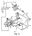
- FIGS. 1 to 4 the same references have been used to designate the same elements.
- a partially open valve 29 can be seen, in normal operation on command of a computer 130 connected for example to pressure measurement means 131 and / or by a link 132 to other computers.
- the valve of FIG. 1 comprises a shutter 3, the opening of which, on command, is obtained by a set of connecting rods 5,202 connecting the shutter to an actuator 41.
- the actuator 41 is capable of being driven by a motor 410.
- the opening is effected downward by the rotation about the axis 36.
- the valve 29 includes a second flap 3 ′.
- the shutter 3 ′ is driven by a connecting rod 201 connected to the connecting rods 5,201 ensuring the opening of the shutter 3.
- the shutter 3 ′ opens towards the top of FIG. 1.
- the originality of the valve 29 according to the present invention with respect to a pressure recovery valve of known type lies in the fact that at least one flap, for example 3 ′ can rotate around its axis 36 ′ under the action of the pressure exerted for example on the flap 3 ′.
- the coupling is ensured by the weight of the flap 3 ′ and by a return spring 204.
- the spring 204 presses the flap 3 ′ against the drive rod 280
- the flap 3 ′ has a stop 281 perpendicular to the base of the flap 3 ′.
- the connecting rod 280 presses on the stop 281, the spring 204 blocking this stop against the connecting rod 280.
- the motor 410 must overcome the restoring force exerted by the spring 204.
- the valve can open in both directions, automatically and autonomously under the action of a pressure difference as soon as it exceeds a threshold.
- Valves comprising at least one flap free to rotate about its axis and comprising two springs acting in opposite directions do not depart from the scope of the present invention.
- the opening of the valve in normal operation is imposed by the position of the connecting rod 280.
- an opening threshold of the valve 29 it is possible, for example, to act on the return force of the spring 204 as a function of the weight and the area of the shutter.
- valve 29 includes locking means in the closed position to allow hermetic insulation.
- the locking means comprise for example a part 284 integral with the flap 3 ′, a blocking part 285 and an actuator 283.
- the part 284 has two recesses 286.
- the blocking part 285 for example in the form of a fork.
- the fork In normal operation, the fork is placed in a position which does not interfere with the rotation of the flap 3 ′ around the axis 36 ′.
- the actuator 283 rotates the part 285 to close the valve.
- the actuator 283 is an irreversible actuator which keeps the valve 29 closed even in the absence of any control signal.
- the actuator is started by a motor 282 on command from the computer 130.
- the closing instruction is transmitted to the computer 130 for example by line 132.
- the aircraft 200 comprises a pressurized enclosure 201, two wings 25, for example four engines 26, a vertical rudder 23, two tail units 24 and a cockpit 27.
- the pressurized enclosure 201 is delimited by the external structure 21 of the aircraft called the skin and by a rear wall 22.
- the rear wall 22 is relatively fragile to reduce the mass of the aircraft.
- This pressurized enclosure must have two safety valves 300, 310 responsible for limiting the pressure difference between overpressure and depression. the pressurized enclosure and the exterior and thus avoid any deformation of the structure of the aircraft.
- This pressure difference can come from overpressure from a regulation failure and from depression from a rapid change in altitude (urgent descent) for example.
- the aircraft 200 further comprises a control valve 28 and a ventilation valve 29.
- the control valve is designed to execute what is called “flight sequences", that is to say to regulate the pressure internal to ensure passenger comfort.
- the ventilation valve 29 allows complete pressure balancing when the aircraft stops. It should be noted that modern aircraft such as the AIRBUS A300, A310, A320, A330 and A 340 series aircraft contain large volumes and have maneuvering possibilities with rapid altitude change. Thus, it is imperative to be able to carry out rapid pressure balancing to prevent damage to the structure of the aircraft by too great a pressure difference. However, the fact of placing a safety valve and making a hole on the skin of the aircraft has serious drawbacks.
- the safety valves 300 and 310 may prove to be insufficient in the event of an incident.
- the aircraft does not include no safety valves 300 and 310, the valve (s) 28 and / or 29 ensuring safety pressure balancing.
- the ventilation valve which, normally during the flight, is not active, and which, in the case of a rapid descent from the aircraft, would allow, independently, the outside air to go inside, to achieve such a balance.
- valves 28 and 29 are placed on the belly of the aircraft, below the water line.
- it facilitates the maintenance which can be done from below and on the other hand it facilitates the flow of air conditioning air whose intake is located in the upper part of the aircraft.
- it is imperative, to ensure the safety of the aircraft in the event of ditching, to allow locking in the closed position of the valve 29.
- the blocking is obtained by the operation of the switch marked "ditching" on the control panel of the plane.
- the device according to the present invention applies to any device for regulating pressure and / or flow between an enclosure and the exterior or between two enclosures comprising a safety balancing device.
- the invention applies in particular to aircraft construction, to the construction of petroleum refineries, fluid distribution devices and chemical reactors.
Landscapes
- Engineering & Computer Science (AREA)
- General Engineering & Computer Science (AREA)
- Mechanical Engineering (AREA)
- Health & Medical Sciences (AREA)
- General Health & Medical Sciences (AREA)
- Pulmonology (AREA)
- Aviation & Aerospace Engineering (AREA)
- Safety Valves (AREA)
Claims (11)
- Schieber (29) mit zwei Klappen (3, 3′) zur Druckrückgewinnung mit Positionierungsmitteln (41, 410, 5, 201, 202, 280), die seine Öffnung auf Befehl erlauben, dadurch gekennzeichnet, daß er Rückstellmittel (204) aufweist, die eine der Klappen (3′) fest mit den Positionierungsmitteln verbinden, wenn die Druckdifferenz an beiden Seiten der Klappe nicht über einen vorbestimmten Schwellwert hinausgeht, und die Klappe (3′) von den Positionierungsmitteln dann, wenn die Druckdifferenz an beiden Seiten den vorbestimmten Schwellwert überschreitet, so trennt, daß sich die Klappe um ihre Drehachse (36′) drehen kann, um den Schieber zu öffnen.
- Schieber (29) nach Anspruch 1, dadurch gekennzeichnet, daß die Rückstellmittel (204) eine Feder aufweisen.
- Schieber nach Anspruch 1 oder 2, dadurch gekennzeichnet, daß die zu öffnende Klappe (3′) einen Anschlag (281) aufweist, an dem eine Schubstange (280) der Positionierungsmittel in Anlage kommt.
- Schieber nach Anspruch 1, 2 oder 3, dadurch gekennzeichnet, daß die Positionierungsmittel ein Stellglied (41, 410) aufweisen.
- Schieber (29) nach Anspruch 1, 2, 3 oder 4, dadurch gekennzeichnet, daß er Mittel (283, 284, 285) zum Schließen und Verriegeln des Schiebers (29) in einer geschlossen Position unabhängig von den an den beiden Seiten der Klappen (3, 3′) herrschenden Druckverhältnissen aufweist.
- Schieber (29) nach Anspruch 5, dadurch kennzeichnet, daß die Mittel (283, 284, 285) zum Schließen und Verriegeln ein mit der Klappe (3′) fest verbundenes Stück (284) aufweisen, das sich von den Positioniermitteln (41, 410, 5, 202, 201, 280) lösen kann, wobei dieses Stück (284) Öffnungen (286) aufweist, in denen ein Blockierstück (285) unterkommt.
- Schieber nach Anspruch 6, dadurch gekennzeichnet, daß die Mittel (283, 284, 285) zum Schließen und Verriegeln ein Stellglied (283, 285) aufweisen, das auf Befehl das Blockierstück (285) in den Öffnungen (286) drehen lassen kann.
- Luftfahrzeug (200), dadurch gekennzeichnet, daß es wenigstens einen Schieber (29) nach einem der vorhergehenden Ansprüche aufweist.
- Luftfahrzeug (200) nach Anspruch 8, dadurch gekennzeichnet, daß der Schieber (29) ein Belüftungsschieber (29) ist, der dazu bestimmt ist, den Außen- und Innendruck auszugleichen, wenn sich das Luftfahrzeug (200) am Boden befindet.
- Luftfahrzeug (200) nach Anspruch 8 oder 9, dadurch gekennzeichnet, daß sich der Schieber (29) unter dem Einfluß eines zu hohen Außendrucks zum Inneren des Luftfahrzeugs hin öffnet.
- Schieber nach Anspruch 1, dadurch gekennzeichnet, daß die beiden Klappen (3, 3′) durch eine Schubstange (201) verbunden sind, die Mittel (204) aufweist, um die Länge der Schubstange unter der Wirkung einer Differenz der auf die beiden Seiten des Schiebers aufgebrachten Drücke zu variieren.
Applications Claiming Priority (2)
| Application Number | Priority Date | Filing Date | Title |
|---|---|---|---|
| FR8807082 | 1988-05-27 | ||
| FR8807082A FR2632044B1 (fr) | 1988-05-27 | 1988-05-27 | Vanne a ouverture autonome et aeronef comportant une telle vanne |
Publications (2)
| Publication Number | Publication Date |
|---|---|
| EP0344048A1 EP0344048A1 (de) | 1989-11-29 |
| EP0344048B1 true EP0344048B1 (de) | 1993-04-07 |
Family
ID=9366691
Family Applications (1)
| Application Number | Title | Priority Date | Filing Date |
|---|---|---|---|
| EP89401385A Expired - Lifetime EP0344048B1 (de) | 1988-05-27 | 1989-05-19 | Selbständig öffnendes Ventil und Luftfahrzeug, mit einem derartigen Ventil |
Country Status (4)
| Country | Link |
|---|---|
| US (1) | US4960249A (de) |
| EP (1) | EP0344048B1 (de) |
| DE (1) | DE68905859T2 (de) |
| FR (1) | FR2632044B1 (de) |
Families Citing this family (14)
| Publication number | Priority date | Publication date | Assignee | Title |
|---|---|---|---|---|
| US5201830A (en) * | 1990-03-15 | 1993-04-13 | Braswell Marion M | System for controlling ambient pressure within an enclosed environment |
| GB9112928D0 (en) * | 1991-06-15 | 1991-08-14 | British Aerospace | Venting a space to relieve pressure generated by an explosion |
| DE4309058C1 (de) * | 1993-03-20 | 1994-12-08 | Deutsche Aerospace Airbus | Anordnung zur Verhinderung des selbsttätigen Öffnens einer nicht ordnungsgemäß geschlossenen und verriegelten Tür oder Klappe im Flugzeugrumpf |
| DE19628395C2 (de) * | 1996-07-13 | 1998-06-04 | Daimler Benz Aerospace Airbus | System zur Regelung der Abluftmengenströme eines Flugzeuges |
| FR2830564B1 (fr) * | 2001-10-05 | 2003-12-26 | Airbus France | Dispositif et procede de commande de l'ouverture d'urgence d'une porte d'evacuation d'un aeronef |
| US6962324B2 (en) * | 2003-04-30 | 2005-11-08 | Honeywell International, Inc. | Cabin pressure outflow control valve having non-linear flow control characteristics |
| US6945278B2 (en) * | 2003-04-30 | 2005-09-20 | Honeywell International, Inc. | Fully integrated aircraft cabin pressure control system valve |
| US7264017B2 (en) * | 2005-05-12 | 2007-09-04 | Honeywell International, Inc. | Dual-actuator aircraft environmental control system valve |
| US20080197236A1 (en) * | 2007-02-15 | 2008-08-21 | Honeywell International Inc. | Lightweight composite material and metal thrust recovery flapper valve |
| DE102007036999A1 (de) * | 2007-08-06 | 2009-02-19 | Nord-Micro Ag & Co. Ohg | Ausströmventil für ein Luftfahrzeug |
| US9096320B2 (en) * | 2010-09-09 | 2015-08-04 | Honeywell International Inc. | Cabin pressure thrust recovery outflow valve with single door |
| US9475584B2 (en) * | 2011-09-02 | 2016-10-25 | Honeywell International Inc. | Cabin pressure control system thrust recovery outflow valve and method that enable ram air recovery |
| DE102012204217B4 (de) * | 2012-03-16 | 2015-02-12 | Nord-Micro Ag & Co. Ohg | Ventil zur Steuerung des Innendrucks in einer Kabine eines Luftfahrzeugs |
| FR3021626B1 (fr) * | 2014-05-28 | 2017-12-22 | Airbus Operations Sas | Equipement de fuselage formant une porte d'acces et comprenant une vanne de regulation d'echappement d'air de pressurisation |
Citations (1)
| Publication number | Priority date | Publication date | Assignee | Title |
|---|---|---|---|---|
| EP0343020A1 (de) * | 1988-04-18 | 1989-11-23 | Abg-Semca | Automatisch sich öffnendes Ventil und Luftfahrzeug mit einem derartigen Ventil |
Family Cites Families (7)
| Publication number | Priority date | Publication date | Assignee | Title |
|---|---|---|---|---|
| US2407540A (en) * | 1943-04-30 | 1946-09-10 | Douglas Aircraft Co Inc | Cabin pressure control valve |
| US3387804A (en) * | 1967-04-24 | 1968-06-11 | United Aircraft Corp | Valve construction |
| US3426984A (en) * | 1967-04-24 | 1969-02-11 | United Aircraft Corp | Aircraft pressurization outflow valve |
| US3544045A (en) * | 1969-01-10 | 1970-12-01 | Garrett Corp | Thrust recovery outflow control valve |
| US3740006A (en) * | 1971-07-29 | 1973-06-19 | Aircraft Corp | Aircraft cabin outflow valve with torque reduction and noise abatement means |
| US3875963A (en) * | 1973-07-27 | 1975-04-08 | Valve Syst Int Inc | Swing check valve |
| US3883111A (en) * | 1973-09-24 | 1975-05-13 | Acf Ind Inc | Clapper-type check valve |
-
1988
- 1988-05-27 FR FR8807082A patent/FR2632044B1/fr not_active Expired - Lifetime
-
1989
- 1989-05-19 DE DE8989401385T patent/DE68905859T2/de not_active Expired - Lifetime
- 1989-05-19 EP EP89401385A patent/EP0344048B1/de not_active Expired - Lifetime
- 1989-05-24 US US07/356,212 patent/US4960249A/en not_active Expired - Lifetime
Patent Citations (1)
| Publication number | Priority date | Publication date | Assignee | Title |
|---|---|---|---|---|
| EP0343020A1 (de) * | 1988-04-18 | 1989-11-23 | Abg-Semca | Automatisch sich öffnendes Ventil und Luftfahrzeug mit einem derartigen Ventil |
Also Published As
| Publication number | Publication date |
|---|---|
| FR2632044A1 (fr) | 1989-12-01 |
| DE68905859T2 (de) | 1993-07-15 |
| FR2632044B1 (fr) | 1990-12-14 |
| DE68905859D1 (de) | 1993-05-13 |
| EP0344048A1 (de) | 1989-11-29 |
| US4960249A (en) | 1990-10-02 |
Similar Documents
| Publication | Publication Date | Title |
|---|---|---|
| EP0342069B1 (de) | Klappenventil für ein Luftfahrzeug | |
| EP0344048B1 (de) | Selbständig öffnendes Ventil und Luftfahrzeug, mit einem derartigen Ventil | |
| EP0343020A1 (de) | Automatisch sich öffnendes Ventil und Luftfahrzeug mit einem derartigen Ventil | |
| EP0152714B1 (de) | Flugsteuereinrichtung für Luftfahrzeuge | |
| CA3003933C (fr) | Porte de sortie d'urgence d'avion a mecanismes integres et procede d'ouverture/fermeture d'une telle porte | |
| EP3095706B1 (de) | Luftfahrzeuggondel, die mindestens eine um die längsachse der gondel drehbar montierte verkleidung umfasst | |
| US5924445A (en) | Fuel intake device for fuel systems | |
| US9096320B2 (en) | Cabin pressure thrust recovery outflow valve with single door | |
| CN107000853A (zh) | 被设计成便于空间系统在再进入地球大气的过程中消亡的无源装置 | |
| CA2781013C (fr) | Carenage aerodynamique arriere d'un mat de liaison d'un moteur d'aeronef | |
| EP3386862B1 (de) | Ram-air-turbine system umfassend eine vorrichtung um die drehung der turbine zu blockieren | |
| EP1914163A1 (de) | Architektur eines hydraulischen Systems zum Manövrieren der Fahrwerke von Luftschiffen | |
| EP1914164A1 (de) | Architektur eines hydraulischen Systems zum Manövrieren der Fahrwerke eines Luftschiffs | |
| EP2300319B1 (de) | Zylindervorrichtung für flugzeugfahrwerk | |
| CA3138605A1 (fr) | Groupe de poussee pour dispositif de propulsion et dispositif de propulsion associe | |
| FR3102974A1 (fr) | Procédé et dispositif pour élargir le domaine de vol d'un avion de ligne | |
| EP3674587B1 (de) | Druckablassventilanordnung | |
| FR2557854A1 (fr) | Systeme de commandes de vol pour aeronef | |
| EP2981461B1 (de) | Vorrichtung zur steuerung der geschwindigkeit eines raumfahrzeugs während des übergangs von einer raumfahrtphase zu einer flugphase sowie entsprechendes übergangsverfahren | |
| WO2009024661A2 (fr) | Dispositif de liaison entre les deux demi-coquilles d'une nacelle de moteur d'aeronef, et nacelle equipee d'un tel dispositif | |
| EP3848288B1 (de) | Hintere befestigung zwischen einer aufhängesäule und einer tragfläche eines flugzeugs | |
| EP2293982B1 (de) | Treibstoffablasssystem | |
| US8382035B2 (en) | Poppet valve for cabin pressure control systems | |
| EP4516679B1 (de) | Überdrucktür für eine heckhaube eines triebwerkstragmastes eines flugzeugs |
Legal Events
| Date | Code | Title | Description |
|---|---|---|---|
| PUAI | Public reference made under article 153(3) epc to a published international application that has entered the european phase |
Free format text: ORIGINAL CODE: 0009012 |
|
| AK | Designated contracting states |
Kind code of ref document: A1 Designated state(s): DE GB IT |
|
| 17P | Request for examination filed |
Effective date: 19900102 |
|
| 17Q | First examination report despatched |
Effective date: 19910618 |
|
| GRAA | (expected) grant |
Free format text: ORIGINAL CODE: 0009210 |
|
| AK | Designated contracting states |
Kind code of ref document: B1 Designated state(s): DE GB IT |
|
| ITF | It: translation for a ep patent filed | ||
| REF | Corresponds to: |
Ref document number: 68905859 Country of ref document: DE Date of ref document: 19930513 |
|
| GBT | Gb: translation of ep patent filed (gb section 77(6)(a)/1977) |
Effective date: 19930421 |
|
| PLBE | No opposition filed within time limit |
Free format text: ORIGINAL CODE: 0009261 |
|
| STAA | Information on the status of an ep patent application or granted ep patent |
Free format text: STATUS: NO OPPOSITION FILED WITHIN TIME LIMIT |
|
| 26N | No opposition filed | ||
| REG | Reference to a national code |
Ref country code: GB Ref legal event code: IF02 |
|
| PGFP | Annual fee paid to national office [announced via postgrant information from national office to epo] |
Ref country code: GB Payment date: 20020425 Year of fee payment: 14 |
|
| PG25 | Lapsed in a contracting state [announced via postgrant information from national office to epo] |
Ref country code: GB Free format text: LAPSE BECAUSE OF NON-PAYMENT OF DUE FEES Effective date: 20030519 |
|
| GBPC | Gb: european patent ceased through non-payment of renewal fee |
Effective date: 20030519 |
|
| PG25 | Lapsed in a contracting state [announced via postgrant information from national office to epo] |
Ref country code: IT Free format text: LAPSE BECAUSE OF NON-PAYMENT OF DUE FEES;WARNING: LAPSES OF ITALIAN PATENTS WITH EFFECTIVE DATE BEFORE 2007 MAY HAVE OCCURRED AT ANY TIME BEFORE 2007. THE CORRECT EFFECTIVE DATE MAY BE DIFFERENT FROM THE ONE RECORDED. Effective date: 20050519 |
|
| PGFP | Annual fee paid to national office [announced via postgrant information from national office to epo] |
Ref country code: DE Payment date: 20080523 Year of fee payment: 20 |