EP0343990A2 - Reifenleck-Entdeckungsverfahren für ein Zentral-Reifenaufpumpsystem - Google Patents
Reifenleck-Entdeckungsverfahren für ein Zentral-Reifenaufpumpsystem Download PDFInfo
- Publication number
- EP0343990A2 EP0343990A2 EP89305315A EP89305315A EP0343990A2 EP 0343990 A2 EP0343990 A2 EP 0343990A2 EP 89305315 A EP89305315 A EP 89305315A EP 89305315 A EP89305315 A EP 89305315A EP 0343990 A2 EP0343990 A2 EP 0343990A2
- Authority
- EP
- European Patent Office
- Prior art keywords
- tires
- pressure
- conduit
- tire
- calculated value
- Prior art date
- Legal status (The legal status is an assumption and is not a legal conclusion. Google has not performed a legal analysis and makes no representation as to the accuracy of the status listed.)
- Withdrawn
Links
Images


Classifications
-
- B—PERFORMING OPERATIONS; TRANSPORTING
- B60—VEHICLES IN GENERAL
- B60C—VEHICLE TYRES; TYRE INFLATION; TYRE CHANGING; CONNECTING VALVES TO INFLATABLE ELASTIC BODIES IN GENERAL; DEVICES OR ARRANGEMENTS RELATED TO TYRES
- B60C23/00—Devices for measuring, signalling, controlling, or distributing tyre pressure or temperature, specially adapted for mounting on vehicles; Arrangement of tyre inflating devices on vehicles, e.g. of pumps or of tanks; Tyre cooling arrangements
- B60C23/001—Devices for manually or automatically controlling or distributing tyre pressure whilst the vehicle is moving
- B60C23/003—Devices for manually or automatically controlling or distributing tyre pressure whilst the vehicle is moving comprising rotational joints between vehicle-mounted pressure sources and the tyres
- B60C23/00372—Devices for manually or automatically controlling or distributing tyre pressure whilst the vehicle is moving comprising rotational joints between vehicle-mounted pressure sources and the tyres characterised by fluid diagrams
-
- B—PERFORMING OPERATIONS; TRANSPORTING
- B60—VEHICLES IN GENERAL
- B60C—VEHICLE TYRES; TYRE INFLATION; TYRE CHANGING; CONNECTING VALVES TO INFLATABLE ELASTIC BODIES IN GENERAL; DEVICES OR ARRANGEMENTS RELATED TO TYRES
- B60C23/00—Devices for measuring, signalling, controlling, or distributing tyre pressure or temperature, specially adapted for mounting on vehicles; Arrangement of tyre inflating devices on vehicles, e.g. of pumps or of tanks; Tyre cooling arrangements
- B60C23/001—Devices for manually or automatically controlling or distributing tyre pressure whilst the vehicle is moving
- B60C23/003—Devices for manually or automatically controlling or distributing tyre pressure whilst the vehicle is moving comprising rotational joints between vehicle-mounted pressure sources and the tyres
- B60C23/00354—Details of valves
Definitions
- the present invention relates to a method for detecting a leaking tire resulting in a significant pressure imbalance in an on-board central tire inflation system of the type having a plurality of inflatable tires each fluidly communicatable by branch conduit means to a common central conduit having pressure measurement means for measuring a pressure value indicative of the average inflation pressurization of the tires.
- each of the tires will have a wheel-end valve for selectively establishing or blocking fluid communication between the tire and the common central conduit.
- Central tire inflation systems also known as tire traction systems, are well known in the prior art as may be seen by reference to U.S. Patent Nos. 2,634,782; 2,976,906; 2,989,999; 3,099,309; 3,102,573; 3,276,502; 3,276,503; 4,313,483; 4,418,737; 4,421,151; 4,434,833; 4,640,331 and 4,678,017, the disclosures of all of which are hereby incorporated by reference.
- CTIS allow the operator to remotely manually and/or automatically vary and/or maintain the inflation pressure of one or more of the vehicle tires from the vehicle (usually a truck) air system, usually while the vehicle is in motion as well as when the vehicle is at rest.
- a plurality of wheel ends are each fluidly connected by a separate branch conduit to common central conduit which may be connected to a source of pressurized air for inflating the tires, to a source of regulated pressurized air for deflating the tires and/or, to atmosphere for venting the conduits and relieving pressure across the rotating seals.
- the common conduit may also be pressurized by means of a quick release valve or the like to the average pressure of the various branch conduits.
- a single pressure transducer is provided in fluid communication with the common central conduit, remote from the wheel ends, for sensing a value indicative of the pressure or average passage in the inflatable tires.
- CTIS While the on-board CTIS described above is highly advantageous as pressure venting is remote from the wheel ends and a single pressure transducer, located in a relatively well protected location remote from the wheel ends and/or the vehicle under carriage, can be utilized to sense tire inflation of the vehicle tires or groups of tires, the CTIS was not totally satisfactory as a method for detecting, in a relatively short period of time, leakage/damage of a single tire the inflation pressure of which is sensed and controlled as a member of a grouping of tires, was not provided. Failure to sense significant leakage/damage may result in undesirable loss of pressure from the undamaged tires during attempts to inflate the damaged tire(s) which may result in a loss of vehicle mobility.
- a CTIS control system having a method for detecting, in a relatively short period of time, a condition indicative of a leaking/damaged tire in a group of tires whose inflation pressure is measured and controlled as a group by means of a remote pressure transducer fluidly connectable to a common central conduit pressurizable to a pressure indicative of the average pressure of said group of tires.
- the above is accomplished by causing the common conduit to be fluidly connected to all of the tires and then allowed to stabilize and be maintained at a pressure indicative of the current average pressure of the tires, taking a plurality of pressure readings of the pressure in said common conduits at timed intervals, calculating the rate of change (decrease) of said readings and declaring a leaking/damaged tire condition of said calculated rate is less than a predetermined reference value.
- the CTIS controller Upon detection of a leaking/damaged tire condition, the CTIS controller, preferably microprocessor based, will signal the vehicle operator of the condition and shutdown (i.e. close wheel end valves and discontinue pressure sensing/adjusting operation) the CTIS system. The vehicle operator may be allowed to override the shutdown of the CTIS system and resume operation.
- condition and shutdown i.e. close wheel end valves and discontinue pressure sensing/adjusting operation
- the vehicle In addition to improved traction at lower tire inflation pressure, the vehicle will be able to maintain a higher speed over poor ground, and reduce wear and tear on the vehicle, because of the smoother ride over "washboard" type terrain. Conversely, to reduce operating temperature and wear and tear on the tires at highway speed, a higher tire inflation pressure is desired.
- the tire inflation pressures be controllable from the vehicle cab from an on-board source of pressurized fluid and be variable and maintainable with the vehicle in motion as well as when the vehicle is at rest.
- the CTIS control have a method for detecting one of the tires of the group leaking or damaged beyond acceptable limits, to notify the vehicle operator of such condition and to shutoff the CTIS to block fluid communication between the tires of the group to prevent the undamaged tires from undesirably bleeding off into the damaged/leaking tire or deflating through a quick release valve or the like.
- the operator will be provided with means by which the shutoff command can be overriden.
- CTIS control method of the present invention is especially well suited for the type of CTIS 10 schematically illustrated in Figure 1 and disclosed in above-mentioned U.S. Patent No. 4,640,331.
- CTIS 10 measures and controls the inflation pressure of the interior pressurized chambers 12 and 14 of a group of tires 16 and 18, respectively, by causing the chambers to fluidly communicate with a common conduit, the pressurization of which conduit may be selectively increased, decreased, vented to atmospheric and/or measured.
- Tires 16 and 18 are typically grouped for this purpose as carried by an axle or set of axles and being of the same ideal inflation pressurization for various operating conditions.
- Each of the inflatable chambers 12 and 14 of tires 16 and 18 are fluidly connected to a common quick release valve 22 by means of a branch fluid passage, 24 and 26, respectively.
- the fluid passages each include a rotary seal assembly, 28 and 30, and a wheel-end valve assembly, 32 and 34.
- the rotary seal assemblies may be of any construction, such as seen in U.S. Patent No. 4,434, 833, the disclosure of which is incorporated by reference.
- the wheel end valves 32 and 34 are normally closed to block fluid communication between the tire chambers and the quick release valve 22 and are effective to be selectively opened to fluidly communicate the tire chambers and valve 22.
- Wheel end valves 32 and 34 are preferably controlled by pressurization/evacuation in the conduits 24 and 26 and are opened or closed as a group.
- Wheel end valves 32 and 34 may be of the structures illustrated in above-mentioned U.S. Patent Nos. 4,640,331 and 4,678,017.
- Valve 22 includes a valve body 38 defining a first port 40 connected to common conduit 20, a second port 42 connected to passage 24, a third port 44 connected to passage 26 and a fourth port 46 connected to a vent passage 48 to atmosphere.
- the valve body 38 defines a central cavity 50 in which a valve member such as plug-type diaphragm 52 is received.
- the outer periphery 54 of diaphragm 52 cooperates with an annular valve seat 56 to control the flow of fluid between port 40 and the fluidly communicating ports 42 and 44.
- a spring 58 and spring retainer 60 may be utilized to bias the outer periphery 54 into sealing contact with the valve seat 56.
- the central plug portion 62 cooperates with an annular valve seat 64 at port 46 to control the flow of fluid between ports 46 and the fluidly communicating ports 42 and 44.
- Diaphragm plug 62 is biased into sealing engagement with valve seat 64 by means of fluid pressure in conduit 20 acting on upper surface 66.
- the average pressure in passages 24 and 26 act upon the undersurface 68 of the diaphragm.
- quick-release valve 22 The operational characteristics of quick-release valve 22 are that a fluid flow (i.e. flow of higher pressurized fluid to a conduit or chamber at a lower pressurization) may be maintained from port 40 to ports 42 and 44. However, a fluid flow may not be maintained from ports 42 and 44 to port 40 as diaphragm 52 will lift to open ports 42 and 44 to the exhaust port 46. Further, the valve 22, by establishing fluid communication from port 40 to ports 42 and 44, and from the pressure of conduits 20, 24 and 26, ports 42 and 44 (conduits 24 and 26) to exhaust port 46, is effective to equalize at the pressurization of the lower pressurized of conduit 20 or average pressure of conduits 24 and 26.
- quick-release valve 22 through which the various valves at the wheel end assemblies are vented, is located remote from the wheel end assembly and may also be located remotely from the control valve and pressure transducer to be described below.
- a control valve assembly 70 is connected to a source of pressurized fluid, such as on-board compressor 72.
- compressor 72 will communicate with a vehicle air brake wet tank 74 which will supply the air brake system 76 with a higher priority than the CTIS control valve assembly 70.
- the control valve assembly is also connected to a vent passage 78 to atmosphere and to the central conduit 20.
- the control valve assembly is effective to selectively vent conduit 20 to atmosphere to vent passages 24 and 26, to pressurize conduit 20 to a relatively high pressure for inflation of the tires, to pressurize conduit 20 to a relatively low pressure to deflate the tires or to pulse conduit 20 with a high pressure to allow conduit 20 to stabilize at the average pressure in the tire chambers.
- pressurization and venting of conduit 20 is also effective to open and close, respectively, the wheel end valves.
- a pressure transducer 80 is provided for sensing the pressurization of conduit 20 and for providing an output signal indicative thereof. To obtain an accurate measurement of average tire pressure, wheel end valves 32 and 34 must be opened and conduit 20 must be sealed at control valve assembly 70 to allow the pressure in conduit 20 to attempt to stabilize at average tire pressure.
- a second central conduit 82 and a pair of two-way/two-position valves 84 and 86 may be provided to allow the control valves assembly 70 and transducer 80 to be utilized to measure and control a different set of tires.
- a central processing unit (CPU) 88 may be provided for controlling system 10.
- CPU 88 includes conditioning circuits 90 for receiving input signals, such as signals from pressure transducer 80, conditioning circuits 92 for issuing command output signals and logic (hardware or software) for defining logic rules by which the input signals are processed to generate command output signals.
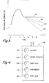
- control valve assembly will pulse conduit 20 from T o to T1 and wait until T2 for pressure in conduit 20 to grossly stabilize at a pressure generally equal to the average pressure in the tires 16 and 18.
- a series of five pressure readings, at T2, T3, T4 and T5, are made to determine the rate of change of pressure during stabilization.
- Line 94 is a representation of expected pressure in conduit 20 if no leakage exists.
- Line 96 is a representation of a maximum acceptable rate of decrease in pressure due to acceptable pressure imbalance, pressure differences due to one tire exposed to sunlight with the other tire in shade, or the like.
- Line 100 is a representation of a rate of decrease in pressure of conduit 20 indicating an imbalance caused a potentially catastrophic failure at one or more of the tires requiring a non-overridable shutdown of the CTIS.
- Line 98 is a representation of a rate of decrease of pressure which is greater than acceptable (line 96) but less than catastrophic (line 100).
- the vehicle operator is warned of the condition, the system is shut down (i.e. automatic periodic pressure corrections are discontinued as are automatic pressure adjustments based upon vehicle speed or the like).
- the operator is provided with an override option allowing reactivation of the system.
- the vehicle operator is provided with a control panel 102, see Figure 4, having five illuminatable buttons, 104, 106, 108, 110 and 112, by which a desired tire pressurization may be selected. If the tire leak check indicates a condition such as represented by line 98, buttons 104, 106, 108 and 110 will be illuminated and/or flashed to inform the operator of the non-catastrophic, but unacceptable, leakage condition. The operator can then choose to override the shutdown by pushing the unlighted button 112 to reactivate the system. If a leakage rate greater than that represented by line 100 is detected, all five buttons will flash and the system shutdown will not be subject to operator override.
- a leakage rate greater than that represented by line 100 is detected, all five buttons will flash and the system shutdown will not be subject to operator override.
- CTIS 10 includes an at-axle portion or portions 114 and a remote portion 116 which may be located anywhere on the vehicle, preferably at a relatively protected location. Further, the at-axle portions 114 of system 10 comprise a stationary portion 118 and rotating portions 120.
Landscapes
- Engineering & Computer Science (AREA)
- Mechanical Engineering (AREA)
- Measuring Fluid Pressure (AREA)
- Examining Or Testing Airtightness (AREA)
Applications Claiming Priority (2)
| Application Number | Priority Date | Filing Date | Title |
|---|---|---|---|
| US19841188A | 1988-05-25 | 1988-05-25 | |
| US198411 | 1988-05-25 |
Publications (2)
| Publication Number | Publication Date |
|---|---|
| EP0343990A2 true EP0343990A2 (de) | 1989-11-29 |
| EP0343990A3 EP0343990A3 (de) | 1990-06-20 |
Family
ID=22733276
Family Applications (1)
| Application Number | Title | Priority Date | Filing Date |
|---|---|---|---|
| EP89305315A Withdrawn EP0343990A3 (de) | 1988-05-25 | 1989-05-25 | Reifenleck-Entdeckungsverfahren für ein Zentral-Reifenaufpumpsystem |
Country Status (6)
| Country | Link |
|---|---|
| EP (1) | EP0343990A3 (de) |
| JP (1) | JPH0220409A (de) |
| KR (1) | KR900017814A (de) |
| BR (1) | BR8902834A (de) |
| IL (1) | IL90173A (de) |
| ZA (1) | ZA893936B (de) |
Cited By (7)
| Publication number | Priority date | Publication date | Assignee | Title |
|---|---|---|---|---|
| US6307017B1 (en) | 1987-09-24 | 2001-10-23 | Biomeasure, Incorporated | Octapeptide bombesin analogs |
| US7273082B2 (en) | 2004-03-05 | 2007-09-25 | Hendrickson Usa, L.L.C. | Tire inflation system apparatus and method |
| WO2008001873A1 (en) | 2006-06-30 | 2008-01-03 | Toyota Jidosha Kabushiki Kaisha | Tire-pressure control apparatus |
| WO2008041423A1 (en) * | 2006-09-29 | 2008-04-10 | Toyota Jidosha Kabushiki Kaisha | Tire-pressure control apparatus |
| EP3216627A1 (de) * | 2016-03-07 | 2017-09-13 | Deere & Company | System zur reifenfülldrucküberwachung für ein nutzfahrzeug |
| GB2551378A (en) * | 2016-06-16 | 2017-12-20 | Bentley Motors Ltd | Method of assessing damage to composite members |
| US20220234397A1 (en) * | 2016-09-06 | 2022-07-28 | Aktv8 LLC | System and method for tire leak detection |
Families Citing this family (1)
| Publication number | Priority date | Publication date | Assignee | Title |
|---|---|---|---|---|
| JP4407695B2 (ja) | 2006-12-28 | 2010-02-03 | トヨタ自動車株式会社 | タイヤ空気圧制御装置 |
Family Cites Families (6)
| Publication number | Priority date | Publication date | Assignee | Title |
|---|---|---|---|---|
| US2989999A (en) * | 1960-05-13 | 1961-06-27 | Letourneau Westinghouse Compan | Tire inflation control system |
| US3099309A (en) * | 1960-06-20 | 1963-07-30 | Horta Luis Congost | Apparatus and devices for automatic control and supervision of the pressure of the tires of vehicle wheels |
| DE3308080A1 (de) * | 1983-03-08 | 1984-09-20 | Robert Bosch Gmbh, 7000 Stuttgart | Vorrichtung zur gegenseitigen anpassung von reifendruck und fahrzeuggeschwindigkeit |
| US4640331A (en) * | 1984-06-04 | 1987-02-03 | Eaton Corporation | Central tire inflation system |
| IT8753066V0 (it) * | 1987-02-25 | 1987-02-25 | Zorzi Esterina | Dispositivo equilibratore di pressione e o di sicurezza per sistemi fluidici particolarmente per pneumatici di autoveicoli |
| IL86553A (en) * | 1987-06-29 | 1991-12-12 | Eaton Corp | Central tire inflation system |
-
1989
- 1989-05-03 IL IL90173A patent/IL90173A/xx unknown
- 1989-05-23 BR BR898902834A patent/BR8902834A/pt unknown
- 1989-05-24 ZA ZA893936A patent/ZA893936B/xx unknown
- 1989-05-25 JP JP1132509A patent/JPH0220409A/ja active Pending
- 1989-05-25 KR KR1019890007001A patent/KR900017814A/ko not_active Ceased
- 1989-05-25 EP EP89305315A patent/EP0343990A3/de not_active Withdrawn
Cited By (14)
| Publication number | Priority date | Publication date | Assignee | Title |
|---|---|---|---|---|
| US6307017B1 (en) | 1987-09-24 | 2001-10-23 | Biomeasure, Incorporated | Octapeptide bombesin analogs |
| US7273082B2 (en) | 2004-03-05 | 2007-09-25 | Hendrickson Usa, L.L.C. | Tire inflation system apparatus and method |
| CN101432152B (zh) * | 2006-06-30 | 2011-09-28 | 丰田自动车株式会社 | 胎压控制设备 |
| WO2008001873A1 (en) | 2006-06-30 | 2008-01-03 | Toyota Jidosha Kabushiki Kaisha | Tire-pressure control apparatus |
| US7760079B2 (en) | 2006-06-30 | 2010-07-20 | Toyota Jidcsha Kabushiki Kaisha | Tire-pressure control apparatus |
| WO2008041423A1 (en) * | 2006-09-29 | 2008-04-10 | Toyota Jidosha Kabushiki Kaisha | Tire-pressure control apparatus |
| US8013724B2 (en) | 2006-09-29 | 2011-09-06 | Toyota Jidosha Kabushiki Kaisha | Tire-pressure control apparatus |
| CN101466559B (zh) * | 2006-09-29 | 2011-11-30 | 丰田自动车株式会社 | 轮胎压力控制设备 |
| EP3216627A1 (de) * | 2016-03-07 | 2017-09-13 | Deere & Company | System zur reifenfülldrucküberwachung für ein nutzfahrzeug |
| US10442256B2 (en) | 2016-03-07 | 2019-10-15 | Deere & Company | System for tire pressure monitoring for a utility vehicle |
| GB2551378A (en) * | 2016-06-16 | 2017-12-20 | Bentley Motors Ltd | Method of assessing damage to composite members |
| US11402291B2 (en) | 2016-06-16 | 2022-08-02 | Bentley Motors Limited | Method of assessing damage to composite members |
| US20220234397A1 (en) * | 2016-09-06 | 2022-07-28 | Aktv8 LLC | System and method for tire leak detection |
| US12179520B2 (en) * | 2016-09-06 | 2024-12-31 | Aktv8 LLC | System and method for tire leak detection |
Also Published As
| Publication number | Publication date |
|---|---|
| KR900017814A (ko) | 1990-12-20 |
| JPH0220409A (ja) | 1990-01-24 |
| ZA893936B (en) | 1990-02-28 |
| BR8902834A (pt) | 1990-11-27 |
| IL90173A0 (en) | 1989-12-15 |
| EP0343990A3 (de) | 1990-06-20 |
| IL90173A (en) | 1991-06-10 |
Similar Documents
| Publication | Publication Date | Title |
|---|---|---|
| EP0344003B1 (de) | Reifenleck-Entdeckungsverfahren für Zentral-Reifenaufpumpsysteme | |
| US5121774A (en) | Fault detection method | |
| US5179981A (en) | Fault detection method for central tire inflation system | |
| US5249609A (en) | Deflation control system and method | |
| US4898216A (en) | CTIS control system and method for sensing and indication of inadequate rate of change of tire inflation pressurization | |
| US4678017A (en) | Wheel end valve for central tire inflation system | |
| US4754792A (en) | Tire valve assembly for central tire inflation system | |
| US4640331A (en) | Central tire inflation system | |
| US4619303A (en) | Vehicle air system including central tire inflation system | |
| US4724879A (en) | Central tire inflation system | |
| EP0297837B1 (de) | Zentrale Reifenfüllungseinrichtung | |
| CA1333929C (en) | Deflation control system and method | |
| EP0368365B1 (de) | Zentrale Reifendruckregelanlage | |
| EP0164916B1 (de) | Zentrales Reifendruckregelsystem | |
| EP0343990A2 (de) | Reifenleck-Entdeckungsverfahren für ein Zentral-Reifenaufpumpsystem | |
| CA1338384C (en) | Fault detection method for central tire inflation system |
Legal Events
| Date | Code | Title | Description |
|---|---|---|---|
| PUAI | Public reference made under article 153(3) epc to a published international application that has entered the european phase |
Free format text: ORIGINAL CODE: 0009012 |
|
| AK | Designated contracting states |
Kind code of ref document: A2 Designated state(s): AT CH DE ES FR GB IT LI NL SE |
|
| PUAL | Search report despatched |
Free format text: ORIGINAL CODE: 0009013 |
|
| AK | Designated contracting states |
Kind code of ref document: A3 Designated state(s): AT CH DE ES FR GB IT LI NL SE |
|
| 17P | Request for examination filed |
Effective date: 19901217 |
|
| STAA | Information on the status of an ep patent application or granted ep patent |
Free format text: STATUS: THE APPLICATION HAS BEEN WITHDRAWN |
|
| 18W | Application withdrawn |
Withdrawal date: 19920310 |