EP0343868A2 - Radiant electric heaters - Google Patents
Radiant electric heaters Download PDFInfo
- Publication number
- EP0343868A2 EP0343868A2 EP89305088A EP89305088A EP0343868A2 EP 0343868 A2 EP0343868 A2 EP 0343868A2 EP 89305088 A EP89305088 A EP 89305088A EP 89305088 A EP89305088 A EP 89305088A EP 0343868 A2 EP0343868 A2 EP 0343868A2
- Authority
- EP
- European Patent Office
- Prior art keywords
- heater
- lamp
- protrusion
- layer
- envelope
- Prior art date
- Legal status (The legal status is an assumption and is not a legal conclusion. Google has not performed a legal analysis and makes no representation as to the accuracy of the status listed.)
- Granted
Links
Images


Classifications
-
- H—ELECTRICITY
- H05—ELECTRIC TECHNIQUES NOT OTHERWISE PROVIDED FOR
- H05B—ELECTRIC HEATING; ELECTRIC LIGHT SOURCES NOT OTHERWISE PROVIDED FOR; CIRCUIT ARRANGEMENTS FOR ELECTRIC LIGHT SOURCES, IN GENERAL
- H05B3/00—Ohmic-resistance heating
- H05B3/68—Heating arrangements specially adapted for cooking plates or analogous hot-plates
- H05B3/74—Non-metallic plates, e.g. vitroceramic, ceramic or glassceramic hobs, also including power or control circuits
- H05B3/744—Lamps as heat source, i.e. heating elements with protective gas envelope, e.g. halogen lamps
-
- H—ELECTRICITY
- H05—ELECTRIC TECHNIQUES NOT OTHERWISE PROVIDED FOR
- H05B—ELECTRIC HEATING; ELECTRIC LIGHT SOURCES NOT OTHERWISE PROVIDED FOR; CIRCUIT ARRANGEMENTS FOR ELECTRIC LIGHT SOURCES, IN GENERAL
- H05B3/00—Ohmic-resistance heating
- H05B3/68—Heating arrangements specially adapted for cooking plates or analogous hot-plates
- H05B3/74—Non-metallic plates, e.g. vitroceramic, ceramic or glassceramic hobs, also including power or control circuits
- H05B3/742—Plates having both lamps and resistive heating elements
Definitions
- This invention relates to radiant electric heaters, and in particular to heaters of the kind incorporating an infra-red source such as an infra-red lamp.
- Infra-red radiant electric heaters incorporating infra-red lamps have been described, for example in patent specifications GB 1 273 023, EP 0 117 346 and GB 2 146 431. Such heaters are typically incorporated in cookers and cooktops having a flat, glass ceramic cooking surface.
- the type of lamp used comprises a tungsten filament supported inside a tubular envelope of fused silica, with electrical connections brought out through hermetic pinch seals at the ends of the envelope.
- the infra-red lamps extend above a reflecting surface and are fixed in position by sandwiching both ends of the lamp envelope in the heater periphery or by bolting the electrical connections to a bracket.
- a radiant electric heater comprising a container, a layer of electrical and thermal insulating material disposed in the container and at least one infra-red source means (such as an infra-red lamp) having an envelope transmissive of infra-red radiation, characterised in that said source means is supported in said container at least in part by at least one protrusion extending from said envelope intermediate the ends of said envelope.
- infra-red source means such as an infra-red lamp
- the configuration of the infra-red lamp or other source means is not constrained as it is if the lamp is supported solely by its ends or by its electrical connections.
- the invention makes the use of circular lamps a practical and economic possibility, without risk of excessive stresses being applied to the lamp envelope.
- the protrusion is of the same material as said envelope.
- the protrusion may comprise a sealed tube communicating with the interior of the envelope, for example a tube used to evacuate and back-fill the envelope during manufacture of the infra-red source means.
- Radiant electric heaters for electric cookers commonly include a wall of insulating material extending around the periphery of a heated area in the heater above the layer of insulating material, and in this case the protrusion may engage with the wall. In particular, the protrusion may be sandwiched between the wall and the layer.
- a radiant electric heater comprising a container, a layer of electrical and thermal insulating material disposed in the container and at least one infra-red source means (such as an infra-red lamp), characterised in that said source means is supported in said container at least in part by at least one protrusion from said insulating material intermediate the ends of said source means.
- a radiant electric heater 10 has a container in the form of a metal dish 12 with an upstanding rim 14 and containing a layer of electrical and thermal insulating material 16.
- This material is for example a microporous insulation which comprises a silica aerogel powder mixed with ceramic fibre reinforcement, titanium dioxide opacifier and a small quantity of alumina powder to resist shrinkage, and which is pressed into the dish 12.
- a ring-shaped wall 18 of ceramic fibre extends around the inside of the rim 14 of the dish 12, on top of the layer 16 and protruding slightly above the edge of the rim 14.
- the wall 18 When installed in a glass ceramic top cooker the wall 18 is pressed against the underside of a glass ceramic cooking surface, shown in dashed outline at 20 in Figure 2, the heater 10 being held in position by a spring or other mounting device (not shown). Prior to installation the wall 18 is retained in position by pins or staples (not shown) extending into the layer 16.
- a heat source is provided in the form of a tungsten-halogen infra-red lamp 22.
- This lamp is generally circular in configuration and contains a tungsten filament 24 supported approximately axially within an infra-red transmissive fused silica envelope 26 on spacers (not shown). These spacers are arranged closely enough together to maintain the filament 24 at the desired distance from the envelope 26 in between each pair of spacers despite the curvature of the envelope 26.
- the filament 24 is secured at each end to connections brought out through flattened hermetic pinch seals 30 at the ends of the envelope 26. These ends are adjacent one another, and the pinch seals 30 extend generally radially of the heater 10 through recesses provided in the underside of the ceramic fibre wall 18 and in the layer 16, and through holes in the rim 14 of the dish 12.
- the surface of the layer 16 is contoured, as shown in Figure 2, to reduce the concentration of heat on the glass ceramic cooking surface 20 immediately above the lamp 22, and to maintain an adequate thickness for the layer 16.
- annular depression 32 under the lamp 22 there is an annular depression 32.
- this depression also helps to minimise the overall height of the heater 10, it is considerably broader than is required for this purpose alone, extending from the ceramic wall 18 to well within the inner circumference of the lamp 26.
- the central region 34 of the layer 16 is made slightly convex.
- a temperature sensitive rod limiter 36 is provided with its probe 38 extending across the heater 10 above the lamp 22.
- This probe typically comprises a silica tube containing a metal rod, which is preferably plated with a reflective material, such as silver, as described in GB 2 146 431.
- a snap-action switch 40 controlled by the probe 38 is connected in series with the lamp 26, which in turn is connected to an electrical connector block 42 mounted at the edge of the dish 12.
- the lamp 22 contains an atmosphere with a halogen gas to help prolong the working life of the lamp and to reduce blackening of the inside surface of the envelope 26.
- the envelope 26 has at least one protrusion, in this case in the form of the tube 46, which is used to evacuate the envelope 26 and back-fill it with gas containing halogen during manufacture of the lamp 22. Thereafter the tube 46 is softened by heating and closed to seal the interior of the envelope 26.
- the exhaust tube 46 is made long enough to extend across the space between the lamp 22 and the ceramic wall 18 and part way between the adjacent surfaces of the wall 18 and the layer 16. In this instance the exhaust tube 46 is positioned mid-way along the lamp 22. The tube 46 is restrained against movement by the wall 18 and the layer 16, and this restraint, together with the clamping of the pinch seals 30 between the wall 18 and the layer 16 supports the lamp 26 against side-to-side and up-and-down movement at diametrically opposed points.
- small ridges 48 of the insulating material extend up from the layer 16 in the annular depression 32 towards the underside of the lamp 22.
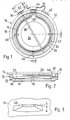
- One of these ridges is shown in greater detail in Figure 3, from which it can be seen to have the shape of a truncated elongate pyramid, with a concave top surface.
- the heat per unit length is less than in the case of straight lamps in a heater of equivalent power rating. This helps to avoid excessive heating of the insulating material forming the ridges 48.
- each ridge 48 measured along the circumference of the lamp 22 (indicated by 'w' in Figure 3) is minimised to limit its effect on the temperature distribution along the lamp.
- the effect of the tube 46 is to limit potential movement of the lamp 22 to rotation about the axis extending from the tube 46 towards the pinch seals 30. However, such rotation would require upward movement of one side of the lamp and downward movement of the other side. Any such downward movement of either side of the lamp 22 is limited by the ridges 48.
- the height of the ridges 48 is chosen so that there is a small clearance (for example 1-1.5 mm) between the top of each ridge and the underside of the lamp 22. This clearance reduces the risk of stress being imposed on the lamp 22 or the tube 46 owing to manufacturing tolerances in the dimensions and shape of the lamp 22.
- a separate tube could be fused to the envelope 26 in such a manner as to maintain the sealing of the envelope 26 undisturbed.
- the ridges 48 may be in the form of ceramic pieces embedded in the layer 16, rather than formed in the layer 16 directly.
- ribs extending across the layer 16 from its outer periphery may be provided. In the case of a relatively small heater the tube 46 alone may be sufficient, and the ridges 48 may be omitted.
- FIGs 4 and 5 show another form of heater 110, in which parts corresponding to those of the heater 10 of Figure 1 have like reference numbers.
- the heater 110 includes a heating source additional to the lamp 22, in the form of a coiled bare resistance wire heating element 112.
- This element is disposed on the layer 16, within the area encompassed by the lamp 22, in a generally circular serpentine configuration to provide an aesthetically pleasing appearance whilst at the same time accommodating the required length of wire and promoting uniform heat distribution.
- the coiled element 112 is secured to the insulating material 16 by, for example, staples held by friction in the insulating material 16, or by gluing to the insulating material 16 or to stakes inserted therein.
- the ends of the wire heating element 112 are coupled to the electrical connector block 42. Where the wire of the coiled element 112 crosses under the lamp 22 it is provided with insulating sleeves 114 to limit the temperature of the wire at that point and also provide additional electrical isolation.
- the exhaust tube 46 is positioned approximately one third the way around the circumference of the lamp 22 from one end.
- a second protrusion 116 in the form of another exhaust tube, or a length of silica tube or rod fused to the envelope 26, is located approximately one third the way around from the other end of the lamp 22.
- This second protrusion is of similar length to the exhaust tube 46, and is attached to the envelope 26 in such a way that it does not disturb the sealing of the interior of the lamp 22.
- the protrusion 116 is restrained against movement by the wall 18 and the insulating material 16 in the same manner as the tube 46.
- the lamp 22 is firmly supported at three points spaced evenly around its circumference, avoiding cantilevering and providing protection against undue stress on the envelope 26 for example in the vicinity of the pinch seals 30. Therefore the ridges 48 are in this case omitted.
- the surface of the insulating material 16 is contoured as with the heater 10 and as shown in Figure 5, to promote uniform distribution of heat around the heater 110.
- protrusions such as 46 and 116 can be varied. Thus more than two protrusions may be provided, for example three spaced from each other by a quarter the circumference of the lamp 22.
- the or each protrusion may be made long enough to extend completely across the ceramic fibre wall 18, into clearance holes provided in the rim 14 of the dish 12. In this way there is increased contact area and less risk of the ceramic fibre wall 18 being locally deformed.
- Each protrusion may be an addition to the lamp 22, instead of using an exhaust tube as a protrusion.
- a protrusion need not extend out towards the ceramic wall 18; it may extend downwardly onto the insulating material 16, providing a support leg for the lamp 22 as shown in dashed line at 120 in Figure 5. However, if every protrusion extends downwardly, some additional form of retention (such as a form of clip described hereinafter) may be desirable to restrain the lamp 22 against upward movement.
- the heater 110 shown in Figures 4 and 5 has a circular lamp surrounding a circular coiled element.
- the lamp 22 may be disposed within the region inside a coiled heating element 212. In this case it may be preferable to arrange for short, straight sections of the element 212 to extend under the protrusions 46 and 116, to provide space for the protrusions and to limit the heat dissipation immediately under them.
- Figure 7 shows a heater 310 in which a coiled heating element 312 has two portions 314 and 316 extending respectively inside and outside the lamp 22. These two portions may be directly coupled in series, as shown in the Figure, or they may be individually connected to terminals in the connector block 42 to enable energisation of the elements in various configurations to provide several different power levels.
- coiled elements 412 and 414 may be provided on each side of the lamp 22, as in the heater 410 shown in Figures 8 and 9, to permit selective heating of differently sized areas of the heater 410.
- an inner wall 416 of ceramic fibre is preferably provided to divide the inner and outer heated areas.
- one or more inwardly directed protrusions may be provided, as indicated in dashed line at 418, instead of or in addition to the outward protrusions 46 and 116 of Figure 4. Such an inwardly directed protrusion may be secured between the inner ceramic wall 416 and the layer of insulating material 16.
- Figure 10 shows a heater 510 similar to that in Figure 4, but with the innermost portion of a coiled element 512 configured in the shape of a star as indicated by the dashed outline.
- a protrusion 50 could be located in a recess 52 in a plateau 54 formed in the insulating material 16.
- the protrusion 50 may be secured for example by glue or by means of a staple 56 straddling the protrusion 50.
- a downwardly directed protrusion may have an enlarged end 58, as shown in Figure 13, designed to be embedded in the insulating material 16 to provide resistance to upward movement of the lamp 22.
- a protrusion may be angled obliquely down from the lamp 22, as shown at 60 in Figure 14, into a recess 62 in the insulating layer 16 under the ceramic fibre wall 18. This likewise provides support against both horizontal and vertical displacement.
- Figures 15 to 18 illustrate various different configurations of protrusion, with transverse projections to provide additional support and retention.
- Figure 19 shows a heater 610 in which clips are used in conjunction with ridges of insulation material to retain the lamp 22 in position.
- the configuration of the heater 610 is generally similar to that of the heater 10 of Figure 1.
- a three-point or tripod type support arrangement is used to provide restraint for the lamp 22 against movement relative to the layer 16.
- One element of this support arrangement comprises the pads 44 under the pinch seals 30.
- small ridges 612 of the insulating material like the ridges 48, extend up from the layer 16 to engage the underside of the lamp 22. In this case there need not be any particular clearance between the ridges 612 and the lamp 22.
- each ridge 612 there is a metal clip 614 extending inwards from the circumference of the heater 610 to engage the upper surface of the lamp 22, so that the lamp 22 is sandwiched between the ridges 612 and the clips 614 at two points around its circumference.
- the clips 614 have an arcuate, elongate portion 616 extending inwards to engage the lamp 22, a base portion 618 which is sandwiched between the wall 18 and the layer 16, and an upstanding portion 620 located between the wall 18 and the rim 14 of the dish 12.
- the angle between the base portion 618 and the upstanding portion 620 is recessed, and holes 622 are provided in the base portion 618 to receive a staple 624, in order to inhibit dislocation of the clip 614.
- tops of the ridges 612 may be concave, as shown in Figures 2 and 3, they may be flat, the clips 614 being used to provide radial location of the lamp 22.
- FIG. 22 An alternative form for the clips 614 is shown in Figure 22.
- the base portion 618 of the clip has two downwardly-directed spikes 626 to engage in the layer 16 and restrain the clip 614 against displacement.
- the elongate portion 616 of the clips 614 may be a substantially complete semi-circle, as shown in dotted line, or it may be only a quadrant of a circle as indicated in solid line.
- FIG. 23 and 24 Another possible form for the clip 614 is shown in Figures 23 and 24.
- the clip has a pointed portion 628 extending from one end of a base portion 630, from the other end of which there extends an upstanding portion 632 with a bent-over lip 634.
- the upstanding portion 632 has a triangular cut-out 636 bent towards the lip 634.
- the lip 634 is pressed down over the rim 14 of the dish 12, so that the cut-out 636 engages with the rim 14 and retains the clip 614 in position.
- FIG. 25 and 26 An additional form for the clip 614 is shown in Figures 25 and 26.
- the clip has a pointed portion 638 extending inwards to engage the lamp 22, and an arcuate base portion 640 which is sandwiched between the wall 18 and the layer 16. Holes 642 and lugs 644 are provided in the base portion 640 to permit the clip to be stapled to the layer 16.
- This configuration has the advantage of avoiding metal-to-metal contact between the clip 614 and the dish 12.
- the clips 614 may be made of wire.
- a clip may be made by bending a length of wire into a narrow V-shaped loop, with the ends extending sideways from the arms of the V. These ends are placed between the wall 18 and the layer 16, with the point of the V extending out over the lamp 22.
- the wire may be bent into a T-shape, the cross-piece of the T being under the wall 18 and the leg extending over the lamp 22.
- the wire may be made of an iron-chromium-aluminium alloy and may be of the order of 1 mm in diameter. If desired a plate, for example of stainless steel, may be placed over the part of the clip under the wall 18 and stapled to the layer 16 to hold the clip down.
- each clip 614 adjacent the lamp 22 may be coated with an electrical insulating material, for example a ceramic such as alumina which may be applied by flame-spraying. Such a coating will also tend to protect against any possible diffusion of metal from the clips 614 into the envelope 26 at high temperature.
- the ridges 612 it is not essential for the ridges 612 to be located directly under the clips 614.
- This arrangement has the advantage that the adjacent clip 614 keeps the lamp 22 firmly in contact with the offset ridge 612a, thereby maintaining the desired clearance between the lamp 22 and the probe 38.
- two ridges of insulation material are provided at 120 degree positions, as in Figure 19, but there are three clips at angular spacings of 90 degrees from each other and from the pinch seals 30.
- only one clip may be provided, diametrically opposite the pinch seals 30. This would restrict the potential movement of the lamp 22 to rotation, in a similar manner to the tube 46 in Figure 1, and such rotation would likewise be inhibited by the ridges without the need for clips directly above them.
- the ridges could be either at 120 degree or 90 degree positions.
- Figures 28 and 29 show alternative forms for the clips, in which they have two spaced arms arranged to clip over and embrace the envelope 26 of the lamp 22. With such clips it is possible to dispense with the ridges.
- Figures 30 and 31 show another form of heater 710 in which two generally semicircular lamps 712 and 714 are used instead of a single circular lamp.
- This has the advantage that the filaments of the two lamps can be selectively switched in series or in parallel, providing different power levels, while retaining the same maximum power level as a single circular lamp.
- the lamps are well supported at each end, using pads 44 under the pinch seals 30 as in the heater of Figure 1.
- restraint is needed to prevent each lamp 712 and 714 from rotating about the axis joining its ends.
- restraint against upward movement is provided by clips 716.
- restraint against downward movement is provided by a protrusion 718 on the lower surface of the envelope 26. This protrusion extends downwards to engage the surface of the layer 16 and maintain the lamp 22 at a predetermined distance above this layer.
- the protrusion 718 is squat and flattened in form and is conveniently made of silica fused to the envelope 26.
- ridges of insulation material like the ridges 48 of Figure 1 could be used instead of the protrusions 718; or a clip could be used to engage the underside of each lamp 712 and 714 as well as the upperside; or a tube like the tube 46 in Figure 1 could be provided at the mid-point of each lamp 712 and 714 to engage between the wall 18 and the layer 16.
- the adjacent ends of the lamps 712 and 714 are connected together by a common ceramic endcap 720.
- the lamps are joined to form a single integral body, with behaves mechanically in a similar manner to the circular lamp of Figure 1.
- the primary mode of displacement is rotation about the axis extending between the lamp ends, and this is sufficiently restrained by protrusions 718 or ridges 48 under the lamps 712 and 714. Thus clips engaging the upper side of the lamps may be omitted.
- the filaments 24 of the two lamps 712 and 714 may be connected to separate conductors at one pair of lamp ends, but may be connected to a common conductor at the other pair of lamp ends. This simplifies the wiring of the heater while preserving the possibility of connecting the lamps 712 and 714 in series or in parallel.
- a bare wire heating coil may be included in the heater of either Figure 30 or 32, in a similar manner to the element 112 in Figure 4 but with separate connections to permit various circuit configurations.
- Figure 33 shows a heater 810 having a small circular lamp 812 in the inner area of the heater and a bare wire heating element 814 surrounding the lamp 812, the element 814 and the lamp 812 being separated by a dividing wall 816 of ceramic fibre.
- the lamp 812 is restrained against movement at three points: at its pinch seals 30; at the point where its ends extend through the dividing wall 816; and by a ridge 48 and clip 818 secured between the dividing wall 816 and the layer 16, diametrically opposite the ends of the lamp 812.
- Figure 34 shows a heater 910 having both a circular lamp 912 in a first heated area and a semi-circular lamp 914 in an adjacent, second heated area, with a dividing wall 916 of ceramic fibre separating the two areas.
- Energisation of the circular lamp 912 alone provides efficient heating of circular utenstils, while energisation of both lamps provides an oval heated area suitable for correspondingly shaped utensils such as casseroles.
- two semi-circular lamps like the lamp 914 could be used as indicated schematically in Figure 34a, to provide additional power level options.
- semi-circular lamps could be provided on both sides of a central circular area, as indicated in Figure 34b.
- Figures 35 and 36 show a heater 1010 having two concentric inner and outer lamps 1012 and 1014, separated by a dividing wall 1016 of ceramic fibre.
- the inner lamp 1012 is intended to be used alone for heating smaller diameter utensils, or together with the outer lamp 1014 for heating larger utensils.
- the sections of its envelope 26a and 26b which traverse the annular part of the heater outside the dividing wall 1016 are coated with black paint, as are the ends of the lamp 1014 outside the rim 14.
- the lamps are restrained against movement by ridges 48 of insulation material and clips 1018 secured under the peripheral wall 18 and the dividing wall 1016.
- One of the clips 1018 is shown in Figure 37, and they are secured by staples to the layer 16 of insulation material under both of the walls 18 and 1016.
- the limiter 36 in the heater of Figure 35 must be calibrated so that it operates to limit the temperature of the glass ceramic cooking surface correctly irrespective of whether only the inner lamp 1012 is energised or both lamps 1012 and 1014 are energised. Accordingly the limiter 36 is made insensitive to the heat in the annular area containing the lamp 1014.
- the outer tube of the probe 38 is made in two pieces, a silica section 1020 extending over the inner lamp 1012 and a metal section 1022 extending over the outer annular area of the heater 1010. This metal section 1022 has a similar coefficient of thermal expansion to the metal rod inside it, so that heat in the annular area of the heater 1010 has little or no effect on the operation of the limiter 36.
- the metal section 1022 may be plated, for example with silver, in the same way as the metal rod inside the probe 38.
- a double-ended clip secured under the dividing wall 1016 may be used instead of a clip 1018 extending inwards from the peripheral wall 18, a double-ended clip secured under the dividing wall 1016 may be used.
- a clip is shown in Figure 38 and has a central base portion 1024 to be located under the dividing wall 1016, and arms 1026 extending in opposite directions to engage over the lamps 1012 and 1014.
- Figures 39 and 40 show a heater 1110 which can provide heated areas of two different sizes, as with the heater 1010 of Figure 35, but which includes two bare wire heating elements, one of which is used to limit lamp inrush current.
- a single lamp 1112 is provided, inside a dividing wall 1114, together with a first bare wire element 1116.
- the annular area outside the dividing wall 1114 contains a second bare wire element 1118 which is energised together with the lamp 1112 and the element 1116 for heating larger size utensils.
- the illuminated part of the filament 24 in the lamp 22 of Figure 1 should not extend into the ends of the envelope 26.
- the filament 24 is connected to a rigid support wire 68, curved to match the bend in the envelope 26.
- This support wire is welded to a section of molybdenum foil which is sealed within the pinch seal 30 and is connected to an external electrical connection.
- the non-illuminated arc between the ends of the filament should be as small as possible, and this constrains the bend between each end and the main body of the lamp 22 to have a small radius.
- the lamp is made by first forming and bending the fused silica envelope 26 to the required shape.
- One of the electrical connections and one of the rigid wires 68 are welded to a piece of molybdenum foil, and this assembly is connected to one end of the filament 24.
- the second support wire 68 is connected to the second end of the filament 24, and this end is threaded into one end of the envelope 26.
- the filament 24 is worked around the envelope 26 until it reaches the far end.
- this support wire In order to weld the molybdenum foil and the external connection to the support wire 68 at the second end of the filament 24, this support wire must be brought a short distance out of the end of the envelope 26. This in turn requires the end of the filament 24 already carrying its support wire and foil to pass temporarily into the envelope 26 and around the bend at that end.
- the lamp 22 can be made, but only by increasing the radius of the bend for at least one end of the lamp (although for aesthetic reasons the bend would typically be made the same on both sides of the lamp). As noted above, this increases the length of the non-illuminated arc in the energised lamp and is therefore considered undesirable.
- Figure 41 shows a heater 1210 incorporating a lamp 1212 which avoids this problem.
- the envelope 26 is formed with two concave-outwards bends 1214 and 1216 in place of a single concave-outwards bend.
- the bends 1214 and 1216 are both of smaller radius than the bend in the lamp 22 of Figure 1, so the length of the non-illuminated arc is smaller than would be the case with a single bend of practicable radius. Nonetheless, we have found that the support wire 68 and the foil will travel further along the envelope 26 than would be the case with a single bend. In particular, they will travel far enough for the foil to be connected to the support wire 68 at the second end of the filament 24.
- Each of the support wires 68 is preferably made with a small right-angled bend at the end to be welded to the molybdenum foil, in the same plane as the bends in the wire which match the bends 1214 and 1216 in the envelope 26. These bends are arranged to be coplanar prior to attachment of the filament 24. Thus, when the molybdenum foils are welded to the support wires 68, the foils and the bends in the support wires 68 will all be in the correct common plane.
- the bend 1214 should be as close as possible to the end extremity of the envelope 26 while leaving sufficient room for the pinch seal 30.
- the second bend 1216 may be positioned as necessary, depending on the dimensions of the lamp 1212 and the envelope 26.
- the configuration of the envelope 26 between the bends 1214 and 1216 is not critical, but it can conveniently be generally straight as shown in the Figure.
- the radii of the bends 1214 and 1216 may be made as small as practicable, within the constraints imposed by the manipulation of the fused silica material.
- the angle of each bend 1214 and 1216 may be approximately half the angle that would be required for a single bend; however, it is advantageous to make the bend 1216 larger than the bend 1214, since the angle of the bend 1214 has a significant effect on the length of the non-illuminated arc.
- the protrusions such as 46 and 116 may be formed by one or more tubes used to exhaust the lamp envelope 26 during manufacture of the lamp.
- a lamp 22 with an envelope 26 having an outer diameter of 8 to 10 mm such an exhaust tube typically has an outer diameter of 4 to 4.5 mm. This has been found to have adequate strength to support the lamp 22, but avoids the need for special shaping of the end of the exhaust tube to match the curvature of the envelope 26.
- these envelope diameters tubes or rods with a diameter somewhat smaller (e.g. 3 mm or less) or larger (e.g. 6 mm or more) may be used in specific embodiments, depending on such parameters as the size of the lamp and the distance between it and the point where the protrusion engages the layer 16 for example.
- lamp support arrangements and heat sources (lamps and wire coils) shown in the drawings are purely exemplary, and other combinations of these arrangements and sources may be used. Likewise other arrangements and combinations of protrusions, ridges and clips are possible.
Landscapes
- Chemical & Material Sciences (AREA)
- Engineering & Computer Science (AREA)
- Ceramic Engineering (AREA)
- Resistance Heating (AREA)
- Electric Stoves And Ranges (AREA)
- Surface Heating Bodies (AREA)
Abstract
Description
- This invention relates to radiant electric heaters, and in particular to heaters of the kind incorporating an infra-red source such as an infra-red lamp.
- Infra-red radiant electric heaters incorporating infra-red lamps have been described, for example in patent specifications GB 1 273 023, EP 0 117 346 and
GB 2 146 431. Such heaters are typically incorporated in cookers and cooktops having a flat, glass ceramic cooking surface. The type of lamp used comprises a tungsten filament supported inside a tubular envelope of fused silica, with electrical connections brought out through hermetic pinch seals at the ends of the envelope. In these heaters the infra-red lamps extend above a reflecting surface and are fixed in position by sandwiching both ends of the lamp envelope in the heater periphery or by bolting the electrical connections to a bracket. Although sandwiching the ends of the envelope is a satisfactory arrangement in the case of relatively short, straight lamps, it would not provide sufficient support in the case of other configurations such as the generally circular lamp shown in GB 1 273 023. In this latter case the lamp would be cantilevered, with the risk of excessive stress being applied to the lamp envelope. Bolting the electrical connections is even less desirable, since it subjects the hermetic pinch seal between the connections and the envelope to considerable stress, especially in the configuration of GB 1 273 023. - Nonetheless, a need exists for lamp configurations other than the existing short, straight arrangements. Such arrangements suffer from the disadvantage of emitting the radiation only from restricted portions of the overall heater area, and these portions do not have an optimum shape. This makes it difficult to provide a heated area with an appropriate distribution of radiation.
- However, at present only short, straight lamps provide sufficient strength and rigidity of mounting to withstand typical use and more particularly the impact tests which such heaters are required to survive as a precaution against damage during transport, storage and use. It is easy to see for example that a heater with a circular lamp supported only at its (adjacent) ends, as in GB 1 273 023, would be very vulnerable to fracture of the lamp if it were dropped or subjected to shock from a utensil falling onto a glass ceramic cooking surface above the heater.
- It is an object of this invention to provide a heater incorporating a lamp which may not be straight but is nonetheless adequately supported.
- According to one aspect of this invention there is provided a radiant electric heater comprising a container, a layer of electrical and thermal insulating material disposed in the container and at least one infra-red source means (such as an infra-red lamp) having an envelope transmissive of infra-red radiation, characterised in that said source means is supported in said container at least in part by at least one protrusion extending from said envelope intermediate the ends of said envelope.
- In such an arrangement the configuration of the infra-red lamp or other source means is not constrained as it is if the lamp is supported solely by its ends or by its electrical connections. In particular, the invention makes the use of circular lamps a practical and economic possibility, without risk of excessive stresses being applied to the lamp envelope.
- Preferably the protrusion is of the same material as said envelope. The protrusion may comprise a sealed tube communicating with the interior of the envelope, for example a tube used to evacuate and back-fill the envelope during manufacture of the infra-red source means.
- Radiant electric heaters for electric cookers commonly include a wall of insulating material extending around the periphery of a heated area in the heater above the layer of insulating material, and in this case the protrusion may engage with the wall. In particular, the protrusion may be sandwiched between the wall and the layer.
- According to another aspect of this invention there is provided a radiant electric heater comprising a container, a layer of electrical and thermal insulating material disposed in the container and at least one infra-red source means (such as an infra-red lamp), characterised in that said source means is supported in said container at least in part by at least one protrusion from said insulating material intermediate the ends of said source means.
- Radiant electric heaters in accordance with this invention for use in a glass ceramic top domestic cooker will now be described, by way of example, with reference to the accompanying drawings, in which:-
- Figure 1 is a plan view of a first heater;
- Figure 2 is a sectional view of the heater of Figure 1;
- Figure 3 is a perspective view of part of the heater of Figure 1;
- Figure 4 is a plan view of a second heater;
- Figure 5 is a sectional view of part of the heater of Figure 4;
- Figure 6 is a plan view of a third heater;
- Figure 7 is a plan view of a fourth heater;
- Figure 8 is a plan view of a fifth heater;
- Figure 9 is a sectional view of part of the heater of Figure 8;
- Figure 10 is a plan view of a sixth heater;
- Figures 11 to 18 illustrate various modifications that may be incorporated in heaters in accordance with the invention;
- Figure 19 is a plan view of a seventh heater;
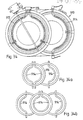
- Figures 20 to 26 show various forms of clip that may be incorporated in the heater of Figure 19;
- Figure 27 is a plan view of an eighth heater;
- Figures 28 and 29 show additional forms of clip that may be incorporated in heaters in accordance with the invention;
- Figure 30 is a plan view of a ninth heater;
- Figure 31 is a sectional view of the heater of Figure 30;
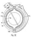
- Figure 32 is a plan view of a tenth heater;
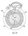
- Figure 33 is a plan view of an eleventh heater;
- Figure 34 is a plan view of a twelfth heater;
- Figures 34a and 34b show modifications of the heater of Figure 34;
- Figure 35 is a plan view of a thirteenth heater;
- Figure 36 is a sectional view of the heater of Figure 35;
- Figure 37 is a perspective view of a component of the heater of Figure 35;
- Figure 38 is a perspective view of an alternative component for use in the heater of Figure 35;
- Figure 39 is a plan view of a fourteenth heater; Figure 40 is a sectional view of the heater of Figure 39; and
- Figure 41 is a plan view of a heater showing a modified form of lamp.
- Referring to Figures 1 to 3, a radiant
electric heater 10 has a container in the form of ametal dish 12 with anupstanding rim 14 and containing a layer of electrical and thermalinsulating material 16. This material is for example a microporous insulation which comprises a silica aerogel powder mixed with ceramic fibre reinforcement, titanium dioxide opacifier and a small quantity of alumina powder to resist shrinkage, and which is pressed into thedish 12. A ring-shaped wall 18 of ceramic fibre extends around the inside of therim 14 of thedish 12, on top of thelayer 16 and protruding slightly above the edge of therim 14. When installed in a glass ceramic top cooker thewall 18 is pressed against the underside of a glass ceramic cooking surface, shown in dashed outline at 20 in Figure 2, theheater 10 being held in position by a spring or other mounting device (not shown). Prior to installation thewall 18 is retained in position by pins or staples (not shown) extending into thelayer 16. - A heat source is provided in the form of a tungsten-halogen infra-
red lamp 22. This lamp is generally circular in configuration and contains atungsten filament 24 supported approximately axially within an infra-red transmissivefused silica envelope 26 on spacers (not shown). These spacers are arranged closely enough together to maintain thefilament 24 at the desired distance from theenvelope 26 in between each pair of spacers despite the curvature of theenvelope 26. Thefilament 24 is secured at each end to connections brought out through flattenedhermetic pinch seals 30 at the ends of theenvelope 26. These ends are adjacent one another, and thepinch seals 30 extend generally radially of theheater 10 through recesses provided in the underside of theceramic fibre wall 18 and in thelayer 16, and through holes in therim 14 of thedish 12. - The surface of the
layer 16 is contoured, as shown in Figure 2, to reduce the concentration of heat on the glassceramic cooking surface 20 immediately above thelamp 22, and to maintain an adequate thickness for thelayer 16. Thus under thelamp 22 there is anannular depression 32. Although the presence of this depression also helps to minimise the overall height of theheater 10, it is considerably broader than is required for this purpose alone, extending from theceramic wall 18 to well within the inner circumference of thelamp 26. In addition to thedepression 32, thecentral region 34 of thelayer 16 is made slightly convex. - As is customary with heaters for glass ceramic top cookers, a temperature
sensitive rod limiter 36 is provided with itsprobe 38 extending across theheater 10 above thelamp 22. This probe typically comprises a silica tube containing a metal rod, which is preferably plated with a reflective material, such as silver, as described inGB 2 146 431. A snap-action switch 40 controlled by theprobe 38 is connected in series with thelamp 26, which in turn is connected to anelectrical connector block 42 mounted at the edge of thedish 12. - To restrain the
lamp 22 against movement relative to thelayer 16, it is secured to thelayer 16 at two spaced positions. Thus, where the pinch seals 30 extend under thewall 18, small raisedpads 44 of the insulating material are formed in thelayer 16 to engage the underside of thelamp 22, the upperside of which engages thewall 18. A second support point is provided diametrically opposite the pinch seals 30, in the form of anelongate exhaust tube 46. - The
lamp 22 contains an atmosphere with a halogen gas to help prolong the working life of the lamp and to reduce blackening of the inside surface of theenvelope 26. To this end theenvelope 26 has at least one protrusion, in this case in the form of thetube 46, which is used to evacuate theenvelope 26 and back-fill it with gas containing halogen during manufacture of thelamp 22. Thereafter thetube 46 is softened by heating and closed to seal the interior of theenvelope 26. - As shown in Figures 1 and 2, the
exhaust tube 46 is made long enough to extend across the space between thelamp 22 and theceramic wall 18 and part way between the adjacent surfaces of thewall 18 and thelayer 16. In this instance theexhaust tube 46 is positioned mid-way along thelamp 22. Thetube 46 is restrained against movement by thewall 18 and thelayer 16, and this restraint, together with the clamping of the pinch seals 30 between thewall 18 and thelayer 16 supports thelamp 26 against side-to-side and up-and-down movement at diametrically opposed points. - In addition, at positions mid-way between the
tube 46 and eachpinch seal 30,small ridges 48 of the insulating material extend up from thelayer 16 in theannular depression 32 towards the underside of thelamp 22. One of these ridges is shown in greater detail in Figure 3, from which it can be seen to have the shape of a truncated elongate pyramid, with a concave top surface. Although the surface of thelamp 22 becomes very hot, the heat per unit length is less than in the case of straight lamps in a heater of equivalent power rating. This helps to avoid excessive heating of the insulating material forming theridges 48. The dimension of eachridge 48 measured along the circumference of the lamp 22 (indicated by 'w' in Figure 3) is minimised to limit its effect on the temperature distribution along the lamp. Thus it is possible to rely on heat conduction along thelamp 22 to limit the increased temperature of thelamp envelope 26 in the vicinity of eachridge 48. - The effect of the
tube 46 is to limit potential movement of thelamp 22 to rotation about the axis extending from thetube 46 towards the pinch seals 30. However, such rotation would require upward movement of one side of the lamp and downward movement of the other side. Any such downward movement of either side of thelamp 22 is limited by theridges 48. - The height of the
ridges 48 is chosen so that there is a small clearance (for example 1-1.5 mm) between the top of each ridge and the underside of thelamp 22. This clearance reduces the risk of stress being imposed on thelamp 22 or thetube 46 owing to manufacturing tolerances in the dimensions and shape of thelamp 22. - Instead of using an exhaust tube to form a support as shown in Figure 1, or in the absence of such a tube, a separate tube could be fused to the
envelope 26 in such a manner as to maintain the sealing of theenvelope 26 undisturbed. - Modifications are also possible to the
ridges 48. Thus for example they may be in the form of ceramic pieces embedded in thelayer 16, rather than formed in thelayer 16 directly. Instead of isolated ridges, ribs extending across thelayer 16 from its outer periphery may be provided. In the case of a relatively small heater thetube 46 alone may be sufficient, and theridges 48 may be omitted. - Figures 4 and 5 show another form of
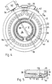
heater 110, in which parts corresponding to those of theheater 10 of Figure 1 have like reference numbers. Referring to Figure 4, theheater 110 includes a heating source additional to thelamp 22, in the form of a coiled bare resistancewire heating element 112. This element is disposed on thelayer 16, within the area encompassed by thelamp 22, in a generally circular serpentine configuration to provide an aesthetically pleasing appearance whilst at the same time accommodating the required length of wire and promoting uniform heat distribution. Thecoiled element 112 is secured to the insulatingmaterial 16 by, for example, staples held by friction in the insulatingmaterial 16, or by gluing to the insulatingmaterial 16 or to stakes inserted therein. The ends of thewire heating element 112 are coupled to theelectrical connector block 42. Where the wire of thecoiled element 112 crosses under thelamp 22 it is provided with insulatingsleeves 114 to limit the temperature of the wire at that point and also provide additional electrical isolation. - In the case of the
heater 110 in Figure 4, theexhaust tube 46 is positioned approximately one third the way around the circumference of thelamp 22 from one end. Asecond protrusion 116 in the form of another exhaust tube, or a length of silica tube or rod fused to theenvelope 26, is located approximately one third the way around from the other end of thelamp 22. This second protrusion is of similar length to theexhaust tube 46, and is attached to theenvelope 26 in such a way that it does not disturb the sealing of the interior of thelamp 22. - The
protrusion 116 is restrained against movement by thewall 18 and the insulatingmaterial 16 in the same manner as thetube 46. Thus thelamp 22 is firmly supported at three points spaced evenly around its circumference, avoiding cantilevering and providing protection against undue stress on theenvelope 26 for example in the vicinity of the pinch seals 30. Therefore theridges 48 are in this case omitted. - The surface of the insulating
material 16 is contoured as with theheater 10 and as shown in Figure 5, to promote uniform distribution of heat around theheater 110. Thus under thelamp 22 there is anannular depression 118, and the insulatingmaterial 16 in the region within the coiledheating element 112 is made slightly convex. - The number, position and nature of the protrusions such as 46 and 116 can be varied. Thus more than two protrusions may be provided, for example three spaced from each other by a quarter the circumference of the
lamp 22. - For additional strength the or each protrusion may be made long enough to extend completely across the
ceramic fibre wall 18, into clearance holes provided in therim 14 of thedish 12. In this way there is increased contact area and less risk of theceramic fibre wall 18 being locally deformed. - Each protrusion may be an addition to the
lamp 22, instead of using an exhaust tube as a protrusion. A protrusion need not extend out towards theceramic wall 18; it may extend downwardly onto the insulatingmaterial 16, providing a support leg for thelamp 22 as shown in dashed line at 120 in Figure 5. However, if every protrusion extends downwardly, some additional form of retention (such as a form of clip described hereinafter) may be desirable to restrain thelamp 22 against upward movement. - The
heater 110 shown in Figures 4 and 5 has a circular lamp surrounding a circular coiled element. However, other arrangements are possible. Thus, in theheater 210 shown in Figure 6, thelamp 22 may be disposed within the region inside acoiled heating element 212. In this case it may be preferable to arrange for short, straight sections of theelement 212 to extend under theprotrusions - Figure 7 shows a
heater 310 in which a coiledheating element 312 has twoportions lamp 22. These two portions may be directly coupled in series, as shown in the Figure, or they may be individually connected to terminals in theconnector block 42 to enable energisation of the elements in various configurations to provide several different power levels. - Alternatively separate
coiled elements lamp 22, as in theheater 410 shown in Figures 8 and 9, to permit selective heating of differently sized areas of theheater 410. In this case, aninner wall 416 of ceramic fibre is preferably provided to divide the inner and outer heated areas. In these circumstances one or more inwardly directed protrusions may be provided, as indicated in dashed line at 418, instead of or in addition to theoutward protrusions ceramic wall 416 and the layer of insulatingmaterial 16. - Figure 10 shows a
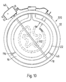
heater 510 similar to that in Figure 4, but with the innermost portion of acoiled element 512 configured in the shape of a star as indicated by the dashed outline. - The protrusions supporting the infra-red lamp need not be secured between the
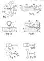
ceramic fibre wall 18 and the insulatingmaterial 16. Thus, as shown in Figures 11 and 12, aprotrusion 50 could be located in arecess 52 in aplateau 54 formed in the insulatingmaterial 16. Theprotrusion 50 may be secured for example by glue or by means of a staple 56 straddling theprotrusion 50. - A downwardly directed protrusion may have an
enlarged end 58, as shown in Figure 13, designed to be embedded in the insulatingmaterial 16 to provide resistance to upward movement of thelamp 22. Alternatively a protrusion may be angled obliquely down from thelamp 22, as shown at 60 in Figure 14, into arecess 62 in the insulatinglayer 16 under theceramic fibre wall 18. This likewise provides support against both horizontal and vertical displacement. - Figures 15 to 18 illustrate various different configurations of protrusion, with transverse projections to provide additional support and retention. The configuration in Figure 17, with a transverse projection 64 inward of the end of a
protrusion 66, permits theprotrusion 66 to rest on the insulatinglayer 16 as well as being clamped between that layer and theceramic wall 18. - Figure 19 shows a
heater 610 in which clips are used in conjunction with ridges of insulation material to retain thelamp 22 in position. Referring to Figure 19, the configuration of theheater 610 is generally similar to that of theheater 10 of Figure 1. However, to provide restraint for thelamp 22 against movement relative to thelayer 16, a three-point or tripod type support arrangement is used. One element of this support arrangement comprises thepads 44 under the pinch seals 30. In addition, at positions spaced 120 degrees around thelamp 22,small ridges 612 of the insulating material, like theridges 48, extend up from thelayer 16 to engage the underside of thelamp 22. In this case there need not be any particular clearance between theridges 612 and thelamp 22. - Above each
ridge 612 there is ametal clip 614 extending inwards from the circumference of theheater 610 to engage the upper surface of thelamp 22, so that thelamp 22 is sandwiched between theridges 612 and theclips 614 at two points around its circumference. - As shown in Figures 20 and 21, the
clips 614 have an arcuate,elongate portion 616 extending inwards to engage thelamp 22, abase portion 618 which is sandwiched between thewall 18 and thelayer 16, and anupstanding portion 620 located between thewall 18 and therim 14 of thedish 12. The angle between thebase portion 618 and theupstanding portion 620 is recessed, and holes 622 are provided in thebase portion 618 to receive astaple 624, in order to inhibit dislocation of theclip 614. - Instead of the tops of the
ridges 612 being concave, as shown in Figures 2 and 3, they may be flat, theclips 614 being used to provide radial location of thelamp 22. - An alternative form for the
clips 614 is shown in Figure 22. In this case thebase portion 618 of the clip has two downwardly-directedspikes 626 to engage in thelayer 16 and restrain theclip 614 against displacement. As also shown in Figure 22, theelongate portion 616 of theclips 614 may be a substantially complete semi-circle, as shown in dotted line, or it may be only a quadrant of a circle as indicated in solid line. - Another possible form for the
clip 614 is shown in Figures 23 and 24. In this case the clip has a pointedportion 628 extending from one end of abase portion 630, from the other end of which there extends anupstanding portion 632 with a bent-overlip 634. Theupstanding portion 632 has a triangular cut-out 636 bent towards thelip 634. Thelip 634 is pressed down over therim 14 of thedish 12, so that the cut-out 636 engages with therim 14 and retains theclip 614 in position. - An additional form for the
clip 614 is shown in Figures 25 and 26. Here the clip has a pointedportion 638 extending inwards to engage thelamp 22, and anarcuate base portion 640 which is sandwiched between thewall 18 and thelayer 16.Holes 642 and lugs 644 are provided in thebase portion 640 to permit the clip to be stapled to thelayer 16. This configuration has the advantage of avoiding metal-to-metal contact between theclip 614 and thedish 12. - Instead of forming the
clips 614 from sheet metal, they may be made of wire. Thus for example a clip may be made by bending a length of wire into a narrow V-shaped loop, with the ends extending sideways from the arms of the V. These ends are placed between thewall 18 and thelayer 16, with the point of the V extending out over thelamp 22. Alternatively the wire may be bent into a T-shape, the cross-piece of the T being under thewall 18 and the leg extending over thelamp 22. The wire may be made of an iron-chromium-aluminium alloy and may be of the order of 1 mm in diameter. If desired a plate, for example of stainless steel, may be placed over the part of the clip under thewall 18 and stapled to thelayer 16 to hold the clip down. - In the case of
clips 614, whether made of sheet or wire, which are in contact with thedish 12, there may be a risk of electrical shorting to thedish 12 in the event that theenvelope 26 breaks just under aclip 614 and allows it to come into contact with thefilament 24. To guard against this problem the end of eachclip 614 adjacent thelamp 22 may be coated with an electrical insulating material, for example a ceramic such as alumina which may be applied by flame-spraying. Such a coating will also tend to protect against any possible diffusion of metal from theclips 614 into theenvelope 26 at high temperature. - It is not essential for the
ridges 612 to be located directly under theclips 614. Thus, as shown in the embodiment of Figure 27, it is possible to have theclips 614 at 120 degree positions as explained above, but to locate one of theridges 612 at an offsetposition 612a so that it supports thelamp 22 directly under the end of thelimiter probe 38 remote from the ends of the lamp. This arrangement has the advantage that theadjacent clip 614 keeps thelamp 22 firmly in contact with the offsetridge 612a, thereby maintaining the desired clearance between thelamp 22 and theprobe 38. - In another possible arrangement two ridges of insulation material are provided at 120 degree positions, as in Figure 19, but there are three clips at angular spacings of 90 degrees from each other and from the pinch seals 30. Alternatively, only one clip may be provided, diametrically opposite the pinch seals 30. This would restrict the potential movement of the
lamp 22 to rotation, in a similar manner to thetube 46 in Figure 1, and such rotation would likewise be inhibited by the ridges without the need for clips directly above them. In this case the ridges could be either at 120 degree or 90 degree positions. - Figures 28 and 29 show alternative forms for the clips, in which they have two spaced arms arranged to clip over and embrace the
envelope 26 of thelamp 22. With such clips it is possible to dispense with the ridges. - Figures 30 and 31 show another form of
heater 710 in which two generallysemicircular lamps pads 44 under the pinch seals 30 as in the heater of Figure 1. However, restraint is needed to prevent eachlamp clips 716. However, restraint against downward movement is provided by aprotrusion 718 on the lower surface of theenvelope 26. This protrusion extends downwards to engage the surface of thelayer 16 and maintain thelamp 22 at a predetermined distance above this layer. Theprotrusion 718 is squat and flattened in form and is conveniently made of silica fused to theenvelope 26. - Alternatively, ridges of insulation material like the
ridges 48 of Figure 1 could be used instead of theprotrusions 718; or a clip could be used to engage the underside of eachlamp tube 46 in Figure 1 could be provided at the mid-point of eachlamp wall 18 and thelayer 16. - In the modified form of heater with two semi-circular lamps shown in Figure 32, the adjacent ends of the
lamps ceramic endcap 720. As a result the lamps are joined to form a single integral body, with behaves mechanically in a similar manner to the circular lamp of Figure 1. The primary mode of displacement is rotation about the axis extending between the lamp ends, and this is sufficiently restrained byprotrusions 718 orridges 48 under thelamps - As shown in Figure 32, the
filaments 24 of the twolamps lamps element 112 in Figure 4 but with separate connections to permit various circuit configurations. - Figure 33 shows a
heater 810 having a smallcircular lamp 812 in the inner area of the heater and a barewire heating element 814 surrounding thelamp 812, theelement 814 and thelamp 812 being separated by a dividingwall 816 of ceramic fibre. In this case thelamp 812 is restrained against movement at three points: at its pinch seals 30; at the point where its ends extend through the dividingwall 816; and by aridge 48 andclip 818 secured between the dividingwall 816 and thelayer 16, diametrically opposite the ends of thelamp 812. - Figure 34 shows a heater 910 having both a
circular lamp 912 in a first heated area and asemi-circular lamp 914 in an adjacent, second heated area, with a dividingwall 916 of ceramic fibre separating the two areas. Energisation of thecircular lamp 912 alone provides efficient heating of circular utenstils, while energisation of both lamps provides an oval heated area suitable for correspondingly shaped utensils such as casseroles. Instead of thecircular lamp 912, two semi-circular lamps like thelamp 914 could be used as indicated schematically in Figure 34a, to provide additional power level options. Furthermore, semi-circular lamps could be provided on both sides of a central circular area, as indicated in Figure 34b. - Figures 35 and 36 show a
heater 1010 having two concentric inner andouter lamps dividing wall 1016 of ceramic fibre. Theinner lamp 1012 is intended to be used alone for heating smaller diameter utensils, or together with theouter lamp 1014 for heating larger utensils. In order to reduce stray light when only theinner lamp 1012 is energised, the sections of itsenvelope wall 1016 are coated with black paint, as are the ends of thelamp 1014 outside therim 14. The lamps are restrained against movement byridges 48 of insulation material andclips 1018 secured under theperipheral wall 18 and thedividing wall 1016. One of theclips 1018 is shown in Figure 37, and they are secured by staples to thelayer 16 of insulation material under both of thewalls - The
limiter 36 in the heater of Figure 35 must be calibrated so that it operates to limit the temperature of the glass ceramic cooking surface correctly irrespective of whether only theinner lamp 1012 is energised or bothlamps limiter 36 is made insensitive to the heat in the annular area containing thelamp 1014. To this end, the outer tube of theprobe 38 is made in two pieces, asilica section 1020 extending over theinner lamp 1012 and a metal section 1022 extending over the outer annular area of theheater 1010. This metal section 1022 has a similar coefficient of thermal expansion to the metal rod inside it, so that heat in the annular area of theheater 1010 has little or no effect on the operation of thelimiter 36. However, there is a possibility of initial heating of the metal section 1022 causing delayed operation of the limiter when thelamps probe 38. - Instead of a
clip 1018 extending inwards from theperipheral wall 18, a double-ended clip secured under the dividingwall 1016 may be used. Such a clip is shown in Figure 38 and has acentral base portion 1024 to be located under the dividingwall 1016, andarms 1026 extending in opposite directions to engage over thelamps - Figures 39 and 40 show a
heater 1110 which can provide heated areas of two different sizes, as with theheater 1010 of Figure 35, but which includes two bare wire heating elements, one of which is used to limit lamp inrush current. Asingle lamp 1112 is provided, inside adividing wall 1114, together with a firstbare wire element 1116. The annular area outside the dividingwall 1114 contains a secondbare wire element 1118 which is energised together with thelamp 1112 and theelement 1116 for heating larger size utensils. - For aesthetic reasons, it is preferred that the illuminated part of the
filament 24 in thelamp 22 of Figure 1, for example, should not extend into the ends of theenvelope 26. Accordingly thefilament 24 is connected to arigid support wire 68, curved to match the bend in theenvelope 26. This support wire is welded to a section of molybdenum foil which is sealed within thepinch seal 30 and is connected to an external electrical connection. - It is also preferred that the non-illuminated arc between the ends of the filament should be as small as possible, and this constrains the bend between each end and the main body of the
lamp 22 to have a small radius. - However, if an attempt is made to maufacture such a lamp with an acceptably small radius, a problem is encountered. The lamp is made by first forming and bending the fused
silica envelope 26 to the required shape. One of the electrical connections and one of therigid wires 68 are welded to a piece of molybdenum foil, and this assembly is connected to one end of thefilament 24. Thesecond support wire 68 is connected to the second end of thefilament 24, and this end is threaded into one end of theenvelope 26. Thefilament 24 is worked around theenvelope 26 until it reaches the far end. In order to weld the molybdenum foil and the external connection to thesupport wire 68 at the second end of thefilament 24, this support wire must be brought a short distance out of the end of theenvelope 26. This in turn requires the end of thefilament 24 already carrying its support wire and foil to pass temporarily into theenvelope 26 and around the bend at that end. - It has been found that with a bend of the desired small radius of curvature it is very difficult or impossible for a
support wire 68 of the desired length, with the foil and external connection, to travel sufficiently far into theenvelope 26. - The
lamp 22 can be made, but only by increasing the radius of the bend for at least one end of the lamp (although for aesthetic reasons the bend would typically be made the same on both sides of the lamp). As noted above, this increases the length of the non-illuminated arc in the energised lamp and is therefore considered undesirable. - Figure 41 shows a
heater 1210 incorporating alamp 1212 which avoids this problem. In making this lamp theenvelope 26 is formed with two concave-outwards bends - The
bends lamp 22 of Figure 1, so the length of the non-illuminated arc is smaller than would be the case with a single bend of practicable radius. Nonetheless, we have found that thesupport wire 68 and the foil will travel further along theenvelope 26 than would be the case with a single bend. In particular, they will travel far enough for the foil to be connected to thesupport wire 68 at the second end of thefilament 24. - Each of the
support wires 68 is preferably made with a small right-angled bend at the end to be welded to the molybdenum foil, in the same plane as the bends in the wire which match thebends envelope 26. These bends are arranged to be coplanar prior to attachment of thefilament 24. Thus, when the molybdenum foils are welded to thesupport wires 68, the foils and the bends in thesupport wires 68 will all be in the correct common plane. - The
bend 1214 should be as close as possible to the end extremity of theenvelope 26 while leaving sufficient room for thepinch seal 30. Thesecond bend 1216 may be positioned as necessary, depending on the dimensions of thelamp 1212 and theenvelope 26. The configuration of theenvelope 26 between thebends - The radii of the
bends bend bend 1216 larger than thebend 1214, since the angle of thebend 1214 has a significant effect on the length of the non-illuminated arc. - Various modifications may be made to the embodiments of the invention described above. Thus, instead of a geometrically circular lamp, it is possible to use a polygonal lamp made by heating and bending the envelope of a straight lamp at points spaced (preferably regularly) along it. With such a lamp the locations of support protrusions, ridges or clips may be determined to coincide with, for example, the mid-point of a straight segment of the lamp.
- As noted above, the protrusions such as 46 and 116 (Figures 1 to 5) may be formed by one or more tubes used to exhaust the
lamp envelope 26 during manufacture of the lamp. For alamp 22 with anenvelope 26 having an outer diameter of 8 to 10 mm such an exhaust tube typically has an outer diameter of 4 to 4.5 mm. This has been found to have adequate strength to support thelamp 22, but avoids the need for special shaping of the end of the exhaust tube to match the curvature of theenvelope 26. It is envisaged that for these envelope diameters tubes or rods with a diameter somewhat smaller (e.g. 3 mm or less) or larger (e.g. 6 mm or more) may be used in specific embodiments, depending on such parameters as the size of the lamp and the distance between it and the point where the protrusion engages thelayer 16 for example. - The particular combinations of lamp support arrangements and heat sources (lamps and wire coils) shown in the drawings are purely exemplary, and other combinations of these arrangements and sources may be used. Likewise other arrangements and combinations of protrusions, ridges and clips are possible.
Claims (19)
Priority Applications (2)
| Application Number | Priority Date | Filing Date | Title |
|---|---|---|---|
| EP93202529A EP0571054B1 (en) | 1988-05-27 | 1989-05-19 | Radiant electric heaters |
| EP92109344A EP0503685B1 (en) | 1988-05-27 | 1989-05-19 | Radiant electric heaters |
Applications Claiming Priority (8)
| Application Number | Priority Date | Filing Date | Title |
|---|---|---|---|
| GB888812600A GB8812600D0 (en) | 1988-05-27 | 1988-05-27 | Radiant electric heaters |
| GB8812600 | 1988-05-27 | ||
| GB888822119A GB8822119D0 (en) | 1988-09-20 | 1988-09-20 | Radiant electric heaters |
| GB8822119 | 1988-09-20 | ||
| GB888830118A GB8830118D0 (en) | 1988-12-23 | 1988-12-23 | Radiant electric heaters |
| GB8830118 | 1988-12-23 | ||
| GB898900777A GB8900777D0 (en) | 1989-01-13 | 1989-01-13 | Incandescent filament lamps |
| GB8900777 | 1989-01-13 |
Related Child Applications (4)
| Application Number | Title | Priority Date | Filing Date |
|---|---|---|---|
| EP93202529A Division EP0571054B1 (en) | 1988-05-27 | 1989-05-19 | Radiant electric heaters |
| EP93202529.9 Division-Into | 1989-05-19 | ||
| EP92109344A Division EP0503685B1 (en) | 1988-05-27 | 1989-05-19 | Radiant electric heaters |
| EP92109344.9 Division-Into | 1989-05-19 |
Publications (3)
| Publication Number | Publication Date |
|---|---|
| EP0343868A2 true EP0343868A2 (en) | 1989-11-29 |
| EP0343868A3 EP0343868A3 (en) | 1991-08-14 |
| EP0343868B1 EP0343868B1 (en) | 1994-06-22 |
Family
ID=27450108
Family Applications (3)
| Application Number | Title | Priority Date | Filing Date |
|---|---|---|---|
| EP93202529A Expired - Lifetime EP0571054B1 (en) | 1988-05-27 | 1989-05-19 | Radiant electric heaters |
| EP92109344A Expired - Lifetime EP0503685B1 (en) | 1988-05-27 | 1989-05-19 | Radiant electric heaters |
| EP89305088A Expired - Lifetime EP0343868B1 (en) | 1988-05-27 | 1989-05-19 | Radiant electric heaters |
Family Applications Before (2)
| Application Number | Title | Priority Date | Filing Date |
|---|---|---|---|
| EP93202529A Expired - Lifetime EP0571054B1 (en) | 1988-05-27 | 1989-05-19 | Radiant electric heaters |
| EP92109344A Expired - Lifetime EP0503685B1 (en) | 1988-05-27 | 1989-05-19 | Radiant electric heaters |
Country Status (10)
| Country | Link |
|---|---|
| US (2) | US5051561A (en) |
| EP (3) | EP0571054B1 (en) |
| JP (1) | JPH0229515A (en) |
| AT (3) | ATE163828T1 (en) |
| AU (1) | AU616759B2 (en) |
| CA (1) | CA1312898C (en) |
| DE (3) | DE68916323T2 (en) |
| ES (3) | ES2113476T3 (en) |
| GB (1) | GB2220333B (en) |
| NZ (1) | NZ229261A (en) |
Cited By (4)
| Publication number | Priority date | Publication date | Assignee | Title |
|---|---|---|---|---|
| EP0771134A3 (en) * | 1995-10-27 | 1997-11-19 | E.G.O. ELEKTRO-GERÄTEBAU GmbH | Radiant heater |
| EP0969698A1 (en) * | 1998-06-30 | 2000-01-05 | Ceramaspeed Limited | Method of manufacturing a radiant electric heater |
| WO2014016178A1 (en) * | 2012-07-23 | 2014-01-30 | Heraeus Noblelight Gmbh | Device for irradiating a substrate |
| EP2111519A4 (en) * | 2007-02-07 | 2016-08-17 | Lg Electronics Inc | Cooking apparatus and heater supporter for the same |
Families Citing this family (22)
| Publication number | Priority date | Publication date | Assignee | Title |
|---|---|---|---|---|
| GB9202036D0 (en) * | 1992-01-30 | 1992-03-18 | Redring Electric Ltd | A heating unit for a hob |
| GB2275161B (en) * | 1993-02-11 | 1996-05-15 | Ceramaspeed Ltd | Method of manufacturing a radiant electric heater |
| USD359653S (en) | 1993-02-11 | 1995-06-27 | Ceramaspeed Limited | Radiant stove heater |
| GB9310514D0 (en) * | 1993-05-21 | 1993-07-07 | Ceramaspeed Ltd | Radiant electric heater |
| USD372638S (en) | 1994-03-02 | 1996-08-13 | Ceramaspeed Limited | Radiant stove heater |
| GB2287388B (en) * | 1994-03-09 | 1997-07-16 | Ceramaspeed Ltd | Radiant electric heater |
| US5544031A (en) * | 1994-11-21 | 1996-08-06 | Blanton; Fred T. | Bracket for decorative lights |
| DE29517021U1 (en) * | 1995-10-27 | 1995-12-21 | E.G.O. Elektro-Geräte Blanc und Fischer GmbH & Co. KG, 75038 Oberderdingen | Radiant heater |
| GB2333406B (en) * | 1998-01-16 | 2001-10-10 | Ceramaspeed Ltd | Radiant electric heater |
| GB2335834B (en) * | 1998-03-26 | 2002-10-23 | Ceramaspeed Ltd | Radiant electric heater |
| GB2336985A (en) * | 1998-04-30 | 1999-11-03 | Ceramaspeed Ltd | A radiant electric heater having both a lamp-form heating element and a ribbon heating element |
| GB2372190B (en) * | 2000-12-16 | 2005-02-09 | Ceramaspeed Ltd | Cooking appliance with radiant electric heater |
| JP2004179089A (en) * | 2002-11-28 | 2004-06-24 | Sanei Denki Seisakusho:Kk | Separable reflection type heating device using ring heater |
| GB0310285D0 (en) * | 2003-05-03 | 2003-06-11 | Ceramaspeed Ltd | Electric heating assembly |
| US9028085B2 (en) * | 2007-11-06 | 2015-05-12 | Alvin E. Todd | Lighting and heating assembly for ceiling fan |
| US9296154B1 (en) * | 2008-08-07 | 2016-03-29 | Mcelroy Manufacturing, Inc. | Tapered wattage radial heater |
| US9380649B2 (en) * | 2010-04-06 | 2016-06-28 | Nichias Corporation | Jacket heater and method for attaching same |
| US8933377B2 (en) | 2011-12-09 | 2015-01-13 | E.G.O. Elektro-Gerätebau GmbH | Control device for an electrical heating device for a cooking field, cooking field and method for operating such an electrical heating device |
| US8884195B2 (en) * | 2011-12-09 | 2014-11-11 | E.G.O. Elektro-Gerätebau GmbH | Heating device, method of producing a heating device and method for operating a heating device |
| WO2018106614A1 (en) * | 2016-12-07 | 2018-06-14 | Ceramaspeed, Inc | Radiant electric heater |
| AU2019349982B2 (en) | 2018-09-25 | 2025-05-29 | Breville Pty Limited | A cooking appliance |
| CN113207198B (en) * | 2020-11-09 | 2022-10-14 | 上海航天精密机械研究所 | Test piece-level quartz lamp heater heat flow uniformity enhancing device and design method thereof |
Family Cites Families (28)
| Publication number | Priority date | Publication date | Assignee | Title |
|---|---|---|---|---|
| US1267287A (en) * | 1917-11-13 | 1918-05-21 | Alexander Silverman | Illuminator for microscopes. |
| US1444400A (en) * | 1920-07-28 | 1923-02-06 | Silverman Alexander | Illuminator for optical instruments |
| US2278951A (en) * | 1939-03-23 | 1942-04-07 | Crosby Steam Gage & Valve Comp | Illuminated dial instrument |
| BE549687A (en) * | 1955-07-21 | |||
| JPS4020199Y1 (en) * | 1964-07-10 | 1965-07-14 | ||
| GB1273023A (en) * | 1969-02-18 | 1972-05-03 | Electricity Council | Improvements in or relating to electric cookers |
| US3612828A (en) * | 1970-06-22 | 1971-10-12 | Gen Motors Corp | Infrared radiant open coil heating unit with reflective fibrous-ceramic heater block |
| GB1433478A (en) * | 1972-08-05 | 1976-04-28 | Mcwilliams J A | Electrical heating apparatus |
| SE7806238L (en) * | 1977-07-02 | 1979-01-03 | Fischer Karl | ELECTRIC RADIATING HEATING ELEMENT, SPECIAL FOR GLASS CERAMIC COOKERS |
| AU3916378A (en) * | 1977-08-23 | 1980-02-28 | Stokes Australasia | Heater unit body |
| US4296311A (en) * | 1979-08-15 | 1981-10-20 | The Kanthal Corporation | Electric hot plate |
| JPS5694264A (en) * | 1979-12-25 | 1981-07-30 | Yuikou Ou | Method and device for detecting live particles using trigger signal |
| JPS6057088B2 (en) * | 1981-10-16 | 1985-12-13 | 松下電器産業株式会社 | Digital/analog conversion method |
| GB2120006B (en) * | 1982-05-07 | 1985-10-09 | Gen Electric Plc | Diversion of heat and light from ribbon seals in high-power electric lamps |
| JPS5959876A (en) * | 1982-09-30 | 1984-04-05 | Ushio Inc | Operating method of light irradiation furnace |
| GB2132060B (en) * | 1982-12-24 | 1985-12-18 | Thorn Emi Domestic Appliances | Heating apparatus |
| US4535228A (en) * | 1982-12-28 | 1985-08-13 | Ushio Denki Kabushiki Kaisha | Heater assembly and a heat-treatment method of semiconductor wafer using the same |
| GB8324271D0 (en) * | 1983-09-10 | 1983-10-12 | Micropore International Ltd | Thermal cut-out device |
| DE3406604C1 (en) * | 1984-02-23 | 1985-07-25 | Bosch-Siemens Hausgeräte GmbH, 7000 Stuttgart | Heating device for radiant heating points with electric radiant heating elements |
| EP0176027B1 (en) * | 1984-09-22 | 1989-02-01 | E.G.O. Elektro-Geräte Blanc u. Fischer | Radiative heating body for a cooking apparatus |
| DE8502949U1 (en) * | 1985-02-04 | 1987-09-03 | E.G.O. Elektro-Geräte Blanc u. Fischer, 7519 Oberderdingen | Radiant heaters for cooking appliances with a bright or high temperature radiant heating element |
| DE3519350A1 (en) * | 1985-05-30 | 1986-12-04 | E.G.O. Elektro-Geräte Blanc u. Fischer, 7519 Oberderdingen | RADIATION HEATING UNIT |
| GB8514785D0 (en) * | 1985-06-11 | 1985-07-10 | Micropore International Ltd | Infra-red heaters |
| GB8520565D0 (en) * | 1985-08-16 | 1985-09-25 | Micropore International Ltd | Radiant electric heaters |
| DE3619919C2 (en) * | 1986-06-13 | 1995-11-09 | Thermal Quarz Schmelze Gmbh | Quartz infrared heater |
| GB8625556D0 (en) * | 1986-10-25 | 1986-11-26 | Micropore International Ltd | Radiant heaters |
| DE8706277U1 (en) * | 1987-05-01 | 1987-06-25 | E.G.O. Elektro-Geräte Blanc u. Fischer, 7519 Oberderdingen | Electric radiant heater for heating a plate, in particular a glass ceramic plate |
| WO1989007737A1 (en) * | 1988-02-22 | 1989-08-24 | Rovicc Incorporated | Cooking range |
-
1989
- 1989-05-19 ES ES93202529T patent/ES2113476T3/en not_active Expired - Lifetime
- 1989-05-19 AT AT93202529T patent/ATE163828T1/en not_active IP Right Cessation
- 1989-05-19 EP EP93202529A patent/EP0571054B1/en not_active Expired - Lifetime
- 1989-05-19 ES ES89305088T patent/ES2055050T3/en not_active Expired - Lifetime
- 1989-05-19 DE DE68916323T patent/DE68916323T2/en not_active Expired - Fee Related
- 1989-05-19 DE DE68923181T patent/DE68923181T2/en not_active Expired - Fee Related
- 1989-05-19 EP EP92109344A patent/EP0503685B1/en not_active Expired - Lifetime
- 1989-05-19 AT AT89305088T patent/ATE107832T1/en not_active IP Right Cessation
- 1989-05-19 EP EP89305088A patent/EP0343868B1/en not_active Expired - Lifetime
- 1989-05-19 DE DE68928596T patent/DE68928596T2/en not_active Expired - Fee Related
- 1989-05-19 AT AT92109344T patent/ATE124198T1/en active
- 1989-05-19 ES ES92109344T patent/ES2073815T3/en not_active Expired - Lifetime
- 1989-05-22 GB GB8911749A patent/GB2220333B/en not_active Expired - Lifetime
- 1989-05-24 NZ NZ229261A patent/NZ229261A/en unknown
- 1989-05-26 US US07/358,328 patent/US5051561A/en not_active Expired - Fee Related
- 1989-05-26 CA CA000600840A patent/CA1312898C/en not_active Expired - Fee Related
- 1989-05-29 JP JP1132954A patent/JPH0229515A/en active Pending
- 1989-05-29 AU AU35284/89A patent/AU616759B2/en not_active Ceased
-
1991
- 1991-07-03 US US07/725,150 patent/US5204510A/en not_active Expired - Lifetime
Cited By (7)
| Publication number | Priority date | Publication date | Assignee | Title |
|---|---|---|---|---|
| EP0771134A3 (en) * | 1995-10-27 | 1997-11-19 | E.G.O. ELEKTRO-GERÄTEBAU GmbH | Radiant heater |
| EP0969698A1 (en) * | 1998-06-30 | 2000-01-05 | Ceramaspeed Limited | Method of manufacturing a radiant electric heater |
| EP2111519A4 (en) * | 2007-02-07 | 2016-08-17 | Lg Electronics Inc | Cooking apparatus and heater supporter for the same |
| WO2014016178A1 (en) * | 2012-07-23 | 2014-01-30 | Heraeus Noblelight Gmbh | Device for irradiating a substrate |
| CN104620367A (en) * | 2012-07-23 | 2015-05-13 | 贺利氏特种光源有限责任公司 | Device for irradiating a substrate |
| US9832817B2 (en) | 2012-07-23 | 2017-11-28 | Heraeus Noblelight Gmbh | Device for irradiating a substrate |
| CN104620367B (en) * | 2012-07-23 | 2018-08-03 | 贺利氏特种光源有限责任公司 | Apparatus for irradiating substrates |
Also Published As
| Publication number | Publication date |
|---|---|
| CA1312898C (en) | 1993-01-19 |
| GB2220333B (en) | 1992-09-02 |
| ATE124198T1 (en) | 1995-07-15 |
| EP0343868B1 (en) | 1994-06-22 |
| EP0571054B1 (en) | 1998-03-04 |
| ES2055050T3 (en) | 1994-08-16 |
| JPH0229515A (en) | 1990-01-31 |
| DE68928596T2 (en) | 1998-07-30 |
| ES2073815T3 (en) | 1995-08-16 |
| EP0503685A2 (en) | 1992-09-16 |
| EP0571054A2 (en) | 1993-11-24 |
| NZ229261A (en) | 1991-11-26 |
| DE68916323D1 (en) | 1994-07-28 |
| EP0343868A3 (en) | 1991-08-14 |
| ATE163828T1 (en) | 1998-03-15 |
| DE68923181T2 (en) | 1995-10-26 |
| EP0571054A3 (en) | 1994-02-16 |
| AU616759B2 (en) | 1991-11-07 |
| US5204510A (en) | 1993-04-20 |
| DE68916323T2 (en) | 1994-10-06 |
| DE68923181D1 (en) | 1995-07-27 |
| ES2113476T3 (en) | 1998-05-01 |
| US5051561A (en) | 1991-09-24 |
| EP0503685B1 (en) | 1995-06-21 |
| EP0503685A3 (en) | 1992-10-07 |
| GB8911749D0 (en) | 1989-07-05 |
| DE68928596D1 (en) | 1998-04-09 |
| AU3528489A (en) | 1989-11-30 |
| GB2220333A (en) | 1990-01-04 |
| ATE107832T1 (en) | 1994-07-15 |
Similar Documents
| Publication | Publication Date | Title |
|---|---|---|
| EP0343868B1 (en) | Radiant electric heaters | |
| US4447711A (en) | Electric heater | |
| US5171973A (en) | Radiant electric heaters | |
| JPH0220249B2 (en) | ||
| US4253012A (en) | Electrical heating units | |
| NZ207620A (en) | Quartz-halogen infra-red lamp: ceramic pinch seal shield | |
| JP2007522606A5 (en) | ||
| EP0429244B1 (en) | Radiant electric heaters | |
| KR19990028205A (en) | Reflector lamp | |
| US5177339A (en) | Radiant electric heaters | |
| GB2181896A (en) | Circuit-breaker for protection of a radiant heating means against overheating | |
| JPH06101850A (en) | Electric heating device for range for cooking | |
| GB2250669A (en) | Electric lamp hotplates | |
| AU720572B2 (en) | Radiant heating body with a metal foil heat conductor | |
| US7132626B2 (en) | Radiant electric heater | |
| US4551617A (en) | Heating apparatus | |
| US3124673A (en) | Surface cooking unit for electric ranges | |
| EP0954202B1 (en) | Radiant electric heater | |
| US6051816A (en) | Radiant electric heater | |
| EP0169643B1 (en) | Heating apparatus | |
| GB2263850A (en) | Supporting an element in a heating unit for a hob | |
| US2317032A (en) | Terminal structure for electric lamps | |
| US2413536A (en) | Electric heater | |
| GB2313994A (en) | Radiant electric heater | |
| EP0969698A1 (en) | Method of manufacturing a radiant electric heater |
Legal Events
| Date | Code | Title | Description |
|---|---|---|---|
| PUAI | Public reference made under article 153(3) epc to a published international application that has entered the european phase |
Free format text: ORIGINAL CODE: 0009012 |
|
| AK | Designated contracting states |
Kind code of ref document: A2 Designated state(s): AT BE CH DE ES FR GB GR IT LI NL SE |
|
| PUAL | Search report despatched |
Free format text: ORIGINAL CODE: 0009013 |
|
| AK | Designated contracting states |
Kind code of ref document: A3 Designated state(s): AT BE CH DE ES FR GB GR IT LI NL SE |
|
| 17P | Request for examination filed |
Effective date: 19920116 |
|
| 17Q | First examination report despatched |
Effective date: 19930528 |
|
| GRAA | (expected) grant |
Free format text: ORIGINAL CODE: 0009210 |
|
| RBV | Designated contracting states (corrected) | ||
| AK | Designated contracting states |
Kind code of ref document: B1 Designated state(s): AT BE CH DE ES FR GR IT LI NL SE |
|
| REF | Corresponds to: |
Ref document number: 107832 Country of ref document: AT Date of ref document: 19940715 Kind code of ref document: T |
|
| XX | Miscellaneous (additional remarks) |
Free format text: TEILANMELDUNG 92109344.9 EINGEREICHT AM 19/05/89. |
|
| ITF | It: translation for a ep patent filed | ||
| ET | Fr: translation filed | ||
| REF | Corresponds to: |
Ref document number: 68916323 Country of ref document: DE Date of ref document: 19940728 |
|
| REG | Reference to a national code |
Ref country code: ES Ref legal event code: FG2A Ref document number: 2055050 Country of ref document: ES Kind code of ref document: T3 |
|
| REG | Reference to a national code |
Ref country code: GR Ref legal event code: FG4A Free format text: 3013252 |
|
| EAL | Se: european patent in force in sweden |
Ref document number: 89305088.0 |
|
| PLBE | No opposition filed within time limit |
Free format text: ORIGINAL CODE: 0009261 |
|
| STAA | Information on the status of an ep patent application or granted ep patent |
Free format text: STATUS: NO OPPOSITION FILED WITHIN TIME LIMIT |
|
| 26N | No opposition filed | ||
| PGFP | Annual fee paid to national office [announced via postgrant information from national office to epo] |
Ref country code: GR Payment date: 19970430 Year of fee payment: 9 Ref country code: CH Payment date: 19970430 Year of fee payment: 9 |
|
| PGFP | Annual fee paid to national office [announced via postgrant information from national office to epo] |
Ref country code: BE Payment date: 19970506 Year of fee payment: 9 |
|
| PGFP | Annual fee paid to national office [announced via postgrant information from national office to epo] |
Ref country code: AT Payment date: 19970513 Year of fee payment: 9 |
|
| PGFP | Annual fee paid to national office [announced via postgrant information from national office to epo] |
Ref country code: SE Payment date: 19970520 Year of fee payment: 9 |
|
| PGFP | Annual fee paid to national office [announced via postgrant information from national office to epo] |
Ref country code: NL Payment date: 19970531 Year of fee payment: 9 |
|
| PG25 | Lapsed in a contracting state [announced via postgrant information from national office to epo] |
Ref country code: AT Free format text: LAPSE BECAUSE OF NON-PAYMENT OF DUE FEES Effective date: 19980519 |
|
| PG25 | Lapsed in a contracting state [announced via postgrant information from national office to epo] |
Ref country code: SE Free format text: LAPSE BECAUSE OF NON-PAYMENT OF DUE FEES Effective date: 19980520 |
|
| PG25 | Lapsed in a contracting state [announced via postgrant information from national office to epo] |
Ref country code: LI Free format text: LAPSE BECAUSE OF NON-PAYMENT OF DUE FEES Effective date: 19980531 Ref country code: GR Free format text: LAPSE BECAUSE OF NON-PAYMENT OF DUE FEES Effective date: 19980531 Ref country code: CH Free format text: LAPSE BECAUSE OF NON-PAYMENT OF DUE FEES Effective date: 19980531 Ref country code: BE Free format text: LAPSE BECAUSE OF NON-PAYMENT OF DUE FEES Effective date: 19980531 |
|
| BERE | Be: lapsed |
Owner name: CERAMASPEED LTD Effective date: 19980531 |
|
| PG25 | Lapsed in a contracting state [announced via postgrant information from national office to epo] |
Ref country code: NL Free format text: LAPSE BECAUSE OF NON-PAYMENT OF DUE FEES Effective date: 19981201 |
|
| REG | Reference to a national code |
Ref country code: CH Ref legal event code: PL |
|
| EUG | Se: european patent has lapsed |
Ref document number: 89305088.0 |
|
| NLV4 | Nl: lapsed or anulled due to non-payment of the annual fee |
Effective date: 19981201 |
|
| PGFP | Annual fee paid to national office [announced via postgrant information from national office to epo] |
Ref country code: DE Payment date: 20020731 Year of fee payment: 14 |
|
| PG25 | Lapsed in a contracting state [announced via postgrant information from national office to epo] |
Ref country code: DE Free format text: LAPSE BECAUSE OF NON-PAYMENT OF DUE FEES Effective date: 20031202 |
|
| PGFP | Annual fee paid to national office [announced via postgrant information from national office to epo] |
Ref country code: ES Payment date: 20040422 Year of fee payment: 16 |
|
| PGFP | Annual fee paid to national office [announced via postgrant information from national office to epo] |
Ref country code: FR Payment date: 20040527 Year of fee payment: 16 |
|
| PG25 | Lapsed in a contracting state [announced via postgrant information from national office to epo] |
Ref country code: IT Free format text: LAPSE BECAUSE OF NON-PAYMENT OF DUE FEES;WARNING: LAPSES OF ITALIAN PATENTS WITH EFFECTIVE DATE BEFORE 2007 MAY HAVE OCCURRED AT ANY TIME BEFORE 2007. THE CORRECT EFFECTIVE DATE MAY BE DIFFERENT FROM THE ONE RECORDED. Effective date: 20050519 |
|
| PG25 | Lapsed in a contracting state [announced via postgrant information from national office to epo] |
Ref country code: ES Free format text: LAPSE BECAUSE OF NON-PAYMENT OF DUE FEES Effective date: 20050520 |
|
| PG25 | Lapsed in a contracting state [announced via postgrant information from national office to epo] |
Ref country code: FR Free format text: LAPSE BECAUSE OF NON-PAYMENT OF DUE FEES Effective date: 20060131 |
|
| REG | Reference to a national code |
Ref country code: FR Ref legal event code: ST Effective date: 20060131 |
|
| REG | Reference to a national code |
Ref country code: ES Ref legal event code: FD2A Effective date: 20050520 |