EP0343799B1 - Separation of gaseous mixtures - Google Patents
Separation of gaseous mixtures Download PDFInfo
- Publication number
- EP0343799B1 EP0343799B1 EP89304424A EP89304424A EP0343799B1 EP 0343799 B1 EP0343799 B1 EP 0343799B1 EP 89304424 A EP89304424 A EP 89304424A EP 89304424 A EP89304424 A EP 89304424A EP 0343799 B1 EP0343799 B1 EP 0343799B1
- Authority
- EP
- European Patent Office
- Prior art keywords
- chambers
- bed
- chamber
- heat exchange
- pressure
- Prior art date
- Legal status (The legal status is an assumption and is not a legal conclusion. Google has not performed a legal analysis and makes no representation as to the accuracy of the status listed.)
- Expired - Lifetime
Links
- 238000000926 separation method Methods 0.000 title claims description 16
- 239000008246 gaseous mixture Substances 0.000 title claims description 11
- 239000007788 liquid Substances 0.000 claims description 64
- 238000001179 sorption measurement Methods 0.000 claims description 41
- 238000003795 desorption Methods 0.000 claims description 24
- 238000000034 method Methods 0.000 claims description 21
- 239000000203 mixture Substances 0.000 claims description 15
- 239000002808 molecular sieve Substances 0.000 claims description 13
- URGAHOPLAPQHLN-UHFFFAOYSA-N sodium aluminosilicate Chemical compound [Na+].[Al+3].[O-][Si]([O-])=O.[O-][Si]([O-])=O URGAHOPLAPQHLN-UHFFFAOYSA-N 0.000 claims description 13
- 239000003463 adsorbent Substances 0.000 claims description 12
- 238000004891 communication Methods 0.000 claims description 12
- 238000007599 discharging Methods 0.000 claims description 4
- 239000012530 fluid Substances 0.000 claims description 4
- 239000000463 material Substances 0.000 claims description 4
- 125000004122 cyclic group Chemical group 0.000 claims description 2
- 239000007789 gas Substances 0.000 description 37
- IJGRMHOSHXDMSA-UHFFFAOYSA-N Atomic nitrogen Chemical compound N#N IJGRMHOSHXDMSA-UHFFFAOYSA-N 0.000 description 12
- 238000005057 refrigeration Methods 0.000 description 11
- 238000009835 boiling Methods 0.000 description 8
- 229910052757 nitrogen Inorganic materials 0.000 description 6
- 230000008569 process Effects 0.000 description 6
- 230000006835 compression Effects 0.000 description 5
- 238000007906 compression Methods 0.000 description 5
- 230000009467 reduction Effects 0.000 description 5
- CURLTUGMZLYLDI-UHFFFAOYSA-N Carbon dioxide Chemical compound O=C=O CURLTUGMZLYLDI-UHFFFAOYSA-N 0.000 description 4
- 230000000694 effects Effects 0.000 description 4
- OKTJSMMVPCPJKN-UHFFFAOYSA-N Carbon Chemical compound [C] OKTJSMMVPCPJKN-UHFFFAOYSA-N 0.000 description 3
- 229910052799 carbon Inorganic materials 0.000 description 3
- 238000009833 condensation Methods 0.000 description 3
- 230000005494 condensation Effects 0.000 description 3
- 229910021536 Zeolite Inorganic materials 0.000 description 2
- QVGXLLKOCUKJST-UHFFFAOYSA-N atomic oxygen Chemical compound [O] QVGXLLKOCUKJST-UHFFFAOYSA-N 0.000 description 2
- 229910002092 carbon dioxide Inorganic materials 0.000 description 2
- 239000001569 carbon dioxide Substances 0.000 description 2
- 230000008859 change Effects 0.000 description 2
- 238000010586 diagram Methods 0.000 description 2
- HNPSIPDUKPIQMN-UHFFFAOYSA-N dioxosilane;oxo(oxoalumanyloxy)alumane Chemical compound O=[Si]=O.O=[Al]O[Al]=O HNPSIPDUKPIQMN-UHFFFAOYSA-N 0.000 description 2
- 239000001301 oxygen Substances 0.000 description 2
- 229910052760 oxygen Inorganic materials 0.000 description 2
- 239000010457 zeolite Substances 0.000 description 2
- RYGMFSIKBFXOCR-UHFFFAOYSA-N Copper Chemical compound [Cu] RYGMFSIKBFXOCR-UHFFFAOYSA-N 0.000 description 1
- 239000004411 aluminium Substances 0.000 description 1
- 229910052782 aluminium Inorganic materials 0.000 description 1
- XAGFODPZIPBFFR-UHFFFAOYSA-N aluminium Chemical compound [Al] XAGFODPZIPBFFR-UHFFFAOYSA-N 0.000 description 1
- 230000008901 benefit Effects 0.000 description 1
- 230000003139 buffering effect Effects 0.000 description 1
- 238000010276 construction Methods 0.000 description 1
- 238000001816 cooling Methods 0.000 description 1
- 229910052802 copper Inorganic materials 0.000 description 1
- 239000010949 copper Substances 0.000 description 1
- 230000003247 decreasing effect Effects 0.000 description 1
- 238000000605 extraction Methods 0.000 description 1
- 230000002349 favourable effect Effects 0.000 description 1
- 238000011049 filling Methods 0.000 description 1
- 238000010438 heat treatment Methods 0.000 description 1
- 238000004519 manufacturing process Methods 0.000 description 1
- 230000007246 mechanism Effects 0.000 description 1
- 229910052751 metal Inorganic materials 0.000 description 1
- 239000002184 metal Substances 0.000 description 1
- 230000008929 regeneration Effects 0.000 description 1
- 238000011069 regeneration method Methods 0.000 description 1
- 238000007873 sieving Methods 0.000 description 1
- 238000011144 upstream manufacturing Methods 0.000 description 1
- 239000011800 void material Substances 0.000 description 1
- XLYOFNOQVPJJNP-UHFFFAOYSA-N water Substances O XLYOFNOQVPJJNP-UHFFFAOYSA-N 0.000 description 1
Images

Classifications
-
- B—PERFORMING OPERATIONS; TRANSPORTING
- B01—PHYSICAL OR CHEMICAL PROCESSES OR APPARATUS IN GENERAL
- B01D—SEPARATION
- B01D53/00—Separation of gases or vapours; Recovering vapours of volatile solvents from gases; Chemical or biological purification of waste gases, e.g. engine exhaust gases, smoke, fumes, flue gases, aerosols
- B01D53/02—Separation of gases or vapours; Recovering vapours of volatile solvents from gases; Chemical or biological purification of waste gases, e.g. engine exhaust gases, smoke, fumes, flue gases, aerosols by adsorption, e.g. preparative gas chromatography
- B01D53/04—Separation of gases or vapours; Recovering vapours of volatile solvents from gases; Chemical or biological purification of waste gases, e.g. engine exhaust gases, smoke, fumes, flue gases, aerosols by adsorption, e.g. preparative gas chromatography with stationary adsorbents
- B01D53/0407—Constructional details of adsorbing systems
- B01D53/0438—Cooling or heating systems
-
- B—PERFORMING OPERATIONS; TRANSPORTING
- B01—PHYSICAL OR CHEMICAL PROCESSES OR APPARATUS IN GENERAL
- B01D—SEPARATION
- B01D53/00—Separation of gases or vapours; Recovering vapours of volatile solvents from gases; Chemical or biological purification of waste gases, e.g. engine exhaust gases, smoke, fumes, flue gases, aerosols
- B01D53/02—Separation of gases or vapours; Recovering vapours of volatile solvents from gases; Chemical or biological purification of waste gases, e.g. engine exhaust gases, smoke, fumes, flue gases, aerosols by adsorption, e.g. preparative gas chromatography
- B01D53/04—Separation of gases or vapours; Recovering vapours of volatile solvents from gases; Chemical or biological purification of waste gases, e.g. engine exhaust gases, smoke, fumes, flue gases, aerosols by adsorption, e.g. preparative gas chromatography with stationary adsorbents
- B01D53/047—Pressure swing adsorption
-
- B—PERFORMING OPERATIONS; TRANSPORTING
- B01—PHYSICAL OR CHEMICAL PROCESSES OR APPARATUS IN GENERAL
- B01D—SEPARATION
- B01D2253/00—Adsorbents used in seperation treatment of gases and vapours
- B01D2253/10—Inorganic adsorbents
- B01D2253/116—Molecular sieves other than zeolites
-
- B—PERFORMING OPERATIONS; TRANSPORTING
- B01—PHYSICAL OR CHEMICAL PROCESSES OR APPARATUS IN GENERAL
- B01D—SEPARATION
- B01D2253/00—Adsorbents used in seperation treatment of gases and vapours
- B01D2253/25—Coated, impregnated or composite adsorbents
-
- B—PERFORMING OPERATIONS; TRANSPORTING
- B01—PHYSICAL OR CHEMICAL PROCESSES OR APPARATUS IN GENERAL
- B01D—SEPARATION
- B01D2256/00—Main component in the product gas stream after treatment
- B01D2256/10—Nitrogen
-
- B—PERFORMING OPERATIONS; TRANSPORTING
- B01—PHYSICAL OR CHEMICAL PROCESSES OR APPARATUS IN GENERAL
- B01D—SEPARATION
- B01D2257/00—Components to be removed
- B01D2257/10—Single element gases other than halogens
- B01D2257/104—Oxygen
-
- B—PERFORMING OPERATIONS; TRANSPORTING
- B01—PHYSICAL OR CHEMICAL PROCESSES OR APPARATUS IN GENERAL
- B01D—SEPARATION
- B01D2257/00—Components to be removed
- B01D2257/50—Carbon oxides
- B01D2257/504—Carbon dioxide
-
- B—PERFORMING OPERATIONS; TRANSPORTING
- B01—PHYSICAL OR CHEMICAL PROCESSES OR APPARATUS IN GENERAL
- B01D—SEPARATION
- B01D2259/00—Type of treatment
- B01D2259/40—Further details for adsorption processes and devices
- B01D2259/402—Further details for adsorption processes and devices using two beds
-
- B—PERFORMING OPERATIONS; TRANSPORTING
- B01—PHYSICAL OR CHEMICAL PROCESSES OR APPARATUS IN GENERAL
- B01D—SEPARATION
- B01D2259/00—Type of treatment
- B01D2259/65—Employing advanced heat integration, e.g. Pinch technology
-
- B—PERFORMING OPERATIONS; TRANSPORTING
- B01—PHYSICAL OR CHEMICAL PROCESSES OR APPARATUS IN GENERAL
- B01D—SEPARATION
- B01D53/00—Separation of gases or vapours; Recovering vapours of volatile solvents from gases; Chemical or biological purification of waste gases, e.g. engine exhaust gases, smoke, fumes, flue gases, aerosols
- B01D53/02—Separation of gases or vapours; Recovering vapours of volatile solvents from gases; Chemical or biological purification of waste gases, e.g. engine exhaust gases, smoke, fumes, flue gases, aerosols by adsorption, e.g. preparative gas chromatography
- B01D53/04—Separation of gases or vapours; Recovering vapours of volatile solvents from gases; Chemical or biological purification of waste gases, e.g. engine exhaust gases, smoke, fumes, flue gases, aerosols by adsorption, e.g. preparative gas chromatography with stationary adsorbents
- B01D53/047—Pressure swing adsorption
- B01D53/0476—Vacuum pressure swing adsorption
-
- Y—GENERAL TAGGING OF NEW TECHNOLOGICAL DEVELOPMENTS; GENERAL TAGGING OF CROSS-SECTIONAL TECHNOLOGIES SPANNING OVER SEVERAL SECTIONS OF THE IPC; TECHNICAL SUBJECTS COVERED BY FORMER USPC CROSS-REFERENCE ART COLLECTIONS [XRACs] AND DIGESTS
- Y02—TECHNOLOGIES OR APPLICATIONS FOR MITIGATION OR ADAPTATION AGAINST CLIMATE CHANGE
- Y02C—CAPTURE, STORAGE, SEQUESTRATION OR DISPOSAL OF GREENHOUSE GASES [GHG]
- Y02C20/00—Capture or disposal of greenhouse gases
- Y02C20/40—Capture or disposal of greenhouse gases of CO2
Definitions
- This invention relates to the separation of gaseous mixtures. It is particularly concerned with a method and apparatus for the separation of gaseous mixture by pressure swing adsorption.
- Pressure swing adsorption entails the passage of a gaseous mixture through a bed of adsorbent that preferentially adsorbs at least one of the components of the mixture.
- a gaseous product that is relatively lean in the adsorbed component or components thus passes out of the bed.
- the bed is then regenerated by subjecting it to a lower pressure whereby the previously adsorbed component or components are desorbed.
- the adsorbent is generally a molecular sieve, typically a zeolite or carbon molecular sieve.
- a plurality of beds is employed and the incoming gas stream for separation is switched between the beds so as to facilitate the continuous supply of gaseous products.
- Pressure swing adsorption processes are for example described in our UK patent applications GB-A-2073043 and GB-A-2163669, and an improved apparatus for separation of gaseous mixture by pressure swing adsorption is described in our UK patent application GB-A-2163670.
- the equilibrium quantity of a gas adsorbed on a molecular sieve is not solely a function of pressure but also one of temperature. Indeed, some commercial gas separation processes rely on a temperature swing rather than a pressure swing to effect separation. Although typical zeolite molecular sieves have gaseous adsorption equilibrium values that are achieved rapidly and then remain constant with time, carbon molecular sieves exhibit a dynamic sieving behaviour before coming to equilibrium (and it is this behaviour which is used), both kinds of sieve increase in temperature as gas is adsorbed since heat of adsorption is liberated, and decrease in temperature again when gas is desorbed. The increase in temperature as a result of adsorption is substantially equal to the decrease in temperature as a result of desorption.
- German Patent DE-C-975393 relates to an adsorption process which includes transferring heat to an adsorbent bed undergoing regeneration by causing vapour to be evolved from a volatile liquid contained in a heat exchanger within an adsorbing bed and causing such vapour to be condensed in a heat exchanger in the desorbing bed.
- a method of separating a gaseous mixture by pressure swing adsorption utilizing at least two beds of adsorbent material capable of adsorbing at least one component of said mixture comprising:
- the invention also provides apparatus for separating a gaseous mixture by pressure swing adsorption, comprising a first vessel containing a first bed of molecular sieve and a second vessel containing a second bed of molecular sieve, a first heat exchange chamber which holds a volume of volatile liquid, and which is located within said first bed, a second heat exchange chamber which holds a volume of said volatile liquid and which is located in said second bed, a conduit connecting a lower portion of said first chamber with a lower portion of said second chamber to permit the flow of volatile liquid therebetween in operation of the apparatus, a second conduit placing the ullage space of one chamber in communication with the ullage space of the other chamber to permit the flow of vapour therebetween, a pressure controller in the ullage spaces of said chambers, and in that the ullage spaces of the chambers communicate with the ullage space of a reservoir containing a volume of said volatile liquid, and valves for controlling the pressure in the ullage space of said reservoir.
- the temperature at which the volatile liquid boils may be readily selected so as to enable condensation in the chamber in heat exchange relationship with the bed for the time being in the desorption mode to take place simultaneously with boiling in the other chamber.
- refrigeration generated in the chamber for the time being in the desorption mode is employed to condense the volatile liquid thereby lessening any temperature reduction that takes place during desorption, while heat evolved during the adsorption step is employed to boil the volatile liquid thereby reducing any temperature rise taking place as a result of the release of the heat of adsorption.
- the reservoir has the effect of dampening any changes in pressure that tend to take place in the chambers and thus helps to keep to manageable proportions any disparity between the rate of condensing vapour in one chamber and the rate of boiling liquid in the other chamber.
- the ability to set the temperature at which the liquid boils and hence the average operating temperature of the beds significantly below ambient temperature may be limited.
- a lower bed operating temperature that can otherwise be achieved may, however, be realised by transferring heat from the incoming gas mixture for separation to the desorbed gas mixture that is discharged from the bed in the desorption mode.
- transfer of heat may be effected by direct heat exchange between the two gases, it is preferably effected by means of an intermediate volatile liquid.
- third and fourth heat exchange chambers both containing a volatile liquid
- the third chamber being in heat exchange relationship with the incoming gas stream for separation and the fourth chamber being heat exchange relationship with the desorbed gas stream
- the volatile liquid employed in the third and fourth chambers may be the same as that in the first and second chambers, and the pressure in the third and fourth chambers may be controlled at a lower value than that in the first and second chambers, or, alternatively, different volatile liquids may be employed in the third and fourth chambers. It can thus be arranged for the liquid in the third and fourth chambers to have a different boiling point from the liquid in the first and second chambers and thus for the temperature of the incoming gas to be reduced substantially to this boiling point upstream of where it is adsorbed.
- the method and apparatus according of the invention are able to meet the aim of the invention by making it possible to reduce the increase in the temperature that takes place during adsorption and the decrease in temperature that takes during desporption and by lowering the average temperature at which adsorption takes place.
- the illustrated plant comprises a first cylindrical vessel 2 containing a bed 6 of molecular sieve adsorbent and a substantially identical vessel 4 containing a bed 8 of the same molecular sieve adsorbent.
- the beds 6 and 8 are of equal height and are located at the same level as one another.
- the apparatus 15 provided with an inlet 10 for incoming gaseous mixture for separation.
- the inlet 10 communicates with a compressor 12 having an outlet 14 terminating in a pipeline 16 which connects the bottoms of the two vessels 2 and 4 with one another.
- the pipeline 16 has a first on-off valve 18 disposed therein.
- the valve 18 is operatively associated with the vessel 2.
- the pipeline 16 has a second on-off valve 20 disposed therein.
- the valve 20 is operatively associated with the vessel 4.
- a pipeline 26 extends from the top of the vessel 2 to the top of the vessel 4.
- An on-off valve 28 is disposed in a portion of the pipeline 26 adjacent the top of the vessel 2.
- Another on-off valve 30 is disposed in the pipeline 26 at a region thereof adjacent the top of the vessel 6.
- a further pipeline 32 extends from the top of the vessel 2 to the top of the vessel 4.
- An on-off valve 34 is disposed in the pipeline 32.
- An outlet 36 communicates with a region of the pipeline 26 intermediate with the valves 28 and 30.
- the outlet 36 has a pressure regulator 38 located therein and may if desired communicate directly with a plant for using the gas produced in operation of the apparatus shown in the drawing or may communicate with such a plant via a buffer vessel (not shown) which is operable to even out cyclical changes in the pressure, flow rate and composition of the product gas in a manner well known in the art.
- a pressure regulator 38 located therein and may if desired communicate directly with a plant for using the gas produced in operation of the apparatus shown in the drawing or may communicate with such a plant via a buffer vessel (not shown) which is operable to even out cyclical changes in the pressure, flow rate and composition of the product gas in a manner well known in the art.
- vent pipe 40 having an on-off valve 42 disposed therein.
- vent pipe 44 having an on-off valve 46 disposed therein communicates with the bottom of the vessel 4.
- vent pipes 42 and 46 vent gas directly to the atmosphere and thus the beds 6 and 8 are never operated at below ambient pressure. It is however alternatively possible to operate the plant by completing the desorption step at a sub-atmospheric pressure, in which case the vent pipes 42 and 46 each communicate with the inlet of vacuum pump (not shown). If such a vacuum pump is employed, it is possible to arrange for the incoming gas to enter the bed 6 and 8 at a pressure in the order of 1 atmosphere absolute, thus enabling the compressor 12 to be dispensed with. In the subsequent description, however, it should be understood that the incoming gas is compressed in the compressor 12 to a pressure above atmospheric pressure and typically in the range 4 to 10 atmospheres absolute and that desorption is effected by placing each bed in turn in communication with the atmosphere.
- a first heat exchange chamber 50 Immersed in the bed 6 is a first heat exchange chamber 50.
- An identical chamber 52 is immersed in the bed 8.
- the chambers 50 and 52 are located in corresponding axial positions in the bed 6 and 8 respectively. Both chambers contain volumes 54 and 56 respectively of a volatile liquid such as a Freon (Freon is a registered trademark).
- a volatile liquid such as a Freon (Freon is a registered trademark).
- Freon Freon is a registered trademark
- the bottoms of the chambers 50 and 52 communicate with one another via a conduit 62 and the tops of the chambers 50 and 52 communicate with one another via a conduit 64.
- An intermediate location of the conduit 64 receives another conduit 66 communicating with the ullage space 68 of a closed reservoir 70 containing a volume 72 of the volatile liquid.
- a liquid reservoir 70 has a fill line 74 with an on-off valve 76 disposed therein and a vent line 78 communicating with its ullage space 68, the vent line 78 having a vent valve 80 disposed therein.
- a pressure sensor (not shown) may be provided for sensing the pressure in the ullage space 70 so as to control operation of the valves 76 and 80 to maintain a substantially constant pressure in the ullage space 68. For example, should the pressure fall below a chosen value, the fill line 74 may be opened so as to admit more volatile liquid into the reservoir 70, and thereby restore the desired pressure, whereas if the pressure rises above the desired pressure in the ullage space 68, the vent valve 80 may be opened to lower the pressure to the desired value again.
- the chambers 50 and 52 are multiple and are preferably provided by heat exchange tubes of a conventional kind having heat exchange fins 53 to assist heat transfer with its surrounds.
- the chambers 50 and 52, and the fins 53 may be formed of aluminium or copper or other metal having high thermal conductivity. It is not necessary for the tubes to contain a large volume of working fluid, although, it is preferred that each of the chambers 50 and 52 has a volume say 10 times in excess of the volume of the conduit 62. Similarly, it is preferred that the reservoir 68 has a volume at least 10 times in excess of the combined volumes of the chambers 50 and 52.
- the liquid employed in the reservoir 68 and in the chambers 50 and 52, and the pressure in the ullage space 68 of reservoir 70 are chosen such that the liquid in the chambers 50 and 52 will boil at a chosen temperature. Throughout the steady-state operation of the apparatus the pressure in the ullage space 68 is maintained so as to prevent any substantial deviation in the temperature at which the liquid boils in the chambers 50 and 52. It is desirable to choose a volatile liquid whose saturation pressure at the desired operating temperature is no more than a few atmospheres so as to avoid the need to manufacture the chambers 50 and 52 and reservoir 70 and associated pipes and valves such that they have to withstand particularly large pressures.
- the apparatus shown in the drawing may be used to separate nitrogen from air.
- the incoming air is compressed to a chosen pressure in the compressor 12 and with only valves 18, 28 and 46 of the on-off valves open, is admitted to the vessel 2.
- Carbon molecular sieve is employed to adsorb carbon dioxide and oxygen in preference to nitrogen.
- particulates and water vapour may be removed from the incoming gas by means (not shown) intermediate the compressor 12 and the pipeline 16.
- a nitrogen-rich gas typically containing at least 95% volume of nitrogen passes out of the vessel 2 and through the outlet 36 as product.
- this step of the cycle may take one to six minutes.
- This step is effected by placing the vessel 4 in communication with the atmosphere through the outlet 44 and as a result gas in the void spaces of the bed is caused to flow out through the bottom of the vessel 4 and as the pressure falls in the bed 8 so gas will be desorbed from the molecular sieve adsorbent and will accordingly also flow out of the bed 8 through the outlet 44.
- the duration of this desorption step is equal to the duration of the adsorption step being performed on the bed 6. In operation, this duration may be selected so as to give a product gas of chosen purity at a given flow rate.
- the duration of these adsorption and desorption steps are equal to one another and equal to that of the first adsorption step in the cycle.
- the valves 20, 30 and 42 are closed again and the valves 24 and 34 opened to allow the pressure between the two beds to be equalised with unadsorbed gas flowing from the bed 8 to the bed 6.
- the duration of this pressure equalisation step is the same of the first pressure equalisation step.
- the valves 24 and 34 are closed and the valves 18, 28 and 46 are reopened and thus the apparatus is in a position to repeat the cycle.
- the temperatures in the beds 6 and 8 are equal to one another and equal to the temperature at which the volatile liquid in the chambers 50 and 52 boils, this temperature being predetermined by the pressure that is maintained in the ullage space 68 of the reservoir 70.
- the volumes of liquid 54, 56 and 72 in the chambers 50 and 52 and the reservoir 70 respectively are in equilibrium with the vapour in the ullage spaces 58, 60 and 68.
- the bed 2 is adsorbing gas from the incoming gaseous mixture and the bed 8 is desorbing previously adsorbed gas. During adsorption in bed 2 heat is generated.
- Heat is thus conducted through the walls of the chamber 50 to the liquid 54 therein and causes some of this liquid to boil at the chosen temperature. There is thus a net flow of vapour into the ullage space 60 and this will condense because this is at the initial temperature. Simultaneously, heat is extracted from the chamber 52 by the gas desorbing from the bed 8. This extraction of heat causes vapour in the ullage space 60 to condense at the chosen temperature. There will thus be a net flow of liquid from the chamber 52 to the chamber 50. The amount of vapour that is condensed will be equal to the amount of liquid boiled so that there is no change in the vapour pressure.
- An increase in the pressure in the ullage spaces of the chambers 50 and 52 causes an increase in the pressure in the ullage space 68 of the chamber 70.
- the vent valve 80 automatically opens to release the excess pressure, and closes again when the pressure in the ullage space 68 has returned to the chosen pressure. Since there is free, unrestricted, communication between ullage spaces of the chambers 50 and 52 and the ullage space 68 of the reservoir 70, the pressure in the ullage spaces 50 and 52 is restored to the chosen pressure and hence the liquid in the chamber for the time being in heat exchange relationship with the bed in the adsorption mode continues to boil at a chosen temperature.
- each adsorption step typically lasts no more than six minutes, the tendency for the rate of condensation of vapour to the exceed the rate of boiling liquid is not a continuing one, but one that is reversed from the first part to the second part of each pressure swing adsorption cycle.
- the pressure in the ullage space 68 of the reservoir 70 may be set to the chosen pressure at which it is desired that the liquid in the chambers 50 and 52 should boil. Typically this temperature may be below ambient temperature. Initially, the gas entering the bed 6 may be at a temperature above ambient temperature. Thus, when it comes to operate bed 6 in the desorption mode the temperature therein may still be above the boiling point of the liquid in the chamber 50, and similarly with the liquid in the chamber 52. Since, however, in each cycle of operations net refrigeration is provided, the average temperature of the beds will gradually fall until stable operating conditions are achieved.
- vapour may be vented from the ullage space 68 of the reservoir 70 so as to maintain the pressure in the ullage spaces 58 and 60 of the chambers 50 and 52 substantially constant during the start-up period. Stable operating conditions will be achieved at a temperature in which the net refrigeration produced in the beds 56 and 58 balance the net heat inleak.
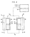
- FIG 2 of the accompanying drawings there is shown an addition to the apparatus in Figure 1 whereby a lower yet stable operating temperature can be achieved.
- the inlet pipe 14 shown in Figure 1 is placed in heat exchange relationship with a common outlet pipe 82 communicating with the outlets 42 and 46 (not shown in Figure 2). It is thus possible to recover refrigeration from the gas that is vented to the atmosphere so that more of the refrigeration generated in the pressure swing adsorption is thereby utilised rather than being wasted.
- the pipe 14 includes a first pass 84 of a heat exchanger 86.
- a second pass of the heat exchanger 86 is constituted by a third heat exchange chamber 88.
- the chamber 88 contains a volume 90 of volatile liquid.
- the bottom of the chamber 88 communicates via a conduit 94 with the bottom of a similar chamber 92 forming a pass of a second heat exchanger 98.
- the chamber 92 contains a volume 96 of volatile liquid.
- a conduit 100 places the ullage space 93 at the top of the chamber 98 in communication with a similar ullage space 103 at the top of the chamber 92.
- Another pass of the heat exchanger 98 forms part of the aforesaid common outlet 82.
- An intermediate location of the conduit 100 communicates with the ullage space of a closed reservoir 110 containing the same volatile liquid as the chambers 84 and 96.
- the construction and operation of the reservoir 110 shown in Figure 2 is substantially the same as that of the reservoir 70 shown in Figure 1 and therefore no further description of the reservoir 110 will be made.
- the volatile liquid is effective to transfer heat from the incoming air for separation to the outgoing vented gas and thereby reduces the temperature of the incoming air before it enters the adsorbent vessels. Accordingly, a lower average working temperature in the beds 6 and 8 of the apparatus shown in Figure 1 is made possible.
- the volatile liquid employed in the chambers 84 and 96 may be the same as or different from that employed by chambers 50 and 52, but if it is the same, a lower working pressure will typically be employed.
- the apparatus shown in Figure 2 may be employed as a simple control mechanism containing plant purity under other varying conditions.
- each chamber containing working fluid may with advantage be replaced by an array of relatively thin chambers.
Landscapes
- Chemical & Material Sciences (AREA)
- Engineering & Computer Science (AREA)
- Analytical Chemistry (AREA)
- General Chemical & Material Sciences (AREA)
- Oil, Petroleum & Natural Gas (AREA)
- Chemical Kinetics & Catalysis (AREA)
- Separation Of Gases By Adsorption (AREA)
Description
- This invention relates to the separation of gaseous mixtures. It is particularly concerned with a method and apparatus for the separation of gaseous mixture by pressure swing adsorption.
- Pressure swing adsorption entails the passage of a gaseous mixture through a bed of adsorbent that preferentially adsorbs at least one of the components of the mixture. A gaseous product that is relatively lean in the adsorbed component or components thus passes out of the bed. The bed is then regenerated by subjecting it to a lower pressure whereby the previously adsorbed component or components are desorbed. The adsorbent is generally a molecular sieve, typically a zeolite or carbon molecular sieve. In more efficient commercial PSA processes, a plurality of beds is employed and the incoming gas stream for separation is switched between the beds so as to facilitate the continuous supply of gaseous products. Pressure swing adsorption processes are for example described in our UK patent applications GB-A-2073043 and GB-A-2163669, and an improved apparatus for separation of gaseous mixture by pressure swing adsorption is described in our UK patent application GB-A-2163670.
- The equilibrium quantity of a gas adsorbed on a molecular sieve is not solely a function of pressure but also one of temperature. Indeed, some commercial gas separation processes rely on a temperature swing rather than a pressure swing to effect separation. Although typical zeolite molecular sieves have gaseous adsorption equilibrium values that are achieved rapidly and then remain constant with time, carbon molecular sieves exhibit a dynamic sieving behaviour before coming to equilibrium (and it is this behaviour which is used), both kinds of sieve increase in temperature as gas is adsorbed since heat of adsorption is liberated, and decrease in temperature again when gas is desorbed. The increase in temperature as a result of adsorption is substantially equal to the decrease in temperature as a result of desorption. There is however typically an additional increase in temperature as a result of the compression of the incoming gas mixture for separation. A substantial proportional of the heat of compression is removed in an after cooler that is conventionally associated with the compressor. There is also a reduction in temperature associated with the reduction in pressure during the desorption step. It might be expected that the PSA process would therefore run at an average temperature below ambient in view of there being net refrigeration that is produced by the pressure reduction required to effect the desorption step. In practice, however, only a relatively small proportion of the refrigeration developed during the desorption step is employed to reduce the temperature of the bed of adsorbent, and most of the refrigeration generated is wasted in the gas that is vented to the atmosphere. Thus, in practice, the average temperature at which the pressure swing adsorption process operates is usually above rather than below ambient temperature. Since the equilibrium amount of gas that is adsorbed increases with decreasing temperature, the failure to make good use of the refrigeration generated is a source of inefficiency and leads to unnecessarily high specific power consumption. Moreover, the temperature rise that takes place during adsorption is also undesirable since lower temperatures generally favour adsorption. The temperature fall that takes place during desorption is similarly undesirable since in general higher temperatures favour desorption.
- There is thus a need to create a more favourable thermal regime during a pressure swing adsorption process and it is an aim of the present invention to provide a method and apparatus for meeting this need.
- German Patent DE-C-975393, relates to an adsorption process which includes transferring heat to an adsorbent bed undergoing regeneration by causing vapour to be evolved from a volatile liquid contained in a heat exchanger within an adsorbing bed and causing such vapour to be condensed in a heat exchanger in the desorbing bed.
- According to the present invention there is provided a method of separating a gaseous mixture by pressure swing adsorption utilizing at least two beds of adsorbent material capable of adsorbing at least one component of said mixture comprising:
- (a) admitting the mixture to a bed of adsorbent material under pressure, thereby adsorbing said at least one component and discharging a gas relatively lean with regard thereto, and
- (b) desorbing said adsorbed at least one component from said bed by subjecting the bed to a pressure lower than that at which adsorption is performed and discharging said at least one component,
- The invention also provides apparatus for separating a gaseous mixture by pressure swing adsorption, comprising a first vessel containing a first bed of molecular sieve and a second vessel containing a second bed of molecular sieve, a first heat exchange chamber which holds a volume of volatile liquid, and which is located within said first bed, a second heat exchange chamber which holds a volume of said volatile liquid and which is located in said second bed, a conduit connecting a lower portion of said first chamber with a lower portion of said second chamber to permit the flow of volatile liquid therebetween in operation of the apparatus, a second conduit placing the ullage space of one chamber in communication with the ullage space of the other chamber to permit the flow of vapour therebetween, a pressure controller in the ullage spaces of said chambers, and in that the ullage spaces of the chambers communicate with the ullage space of a reservoir containing a volume of said volatile liquid, and valves for controlling the pressure in the ullage space of said reservoir.
- By appropriately adjusting the pressure in the ullage space of the reservoir, the temperature at which the volatile liquid boils may be readily selected so as to enable condensation in the chamber in heat exchange relationship with the bed for the time being in the desorption mode to take place simultaneously with boiling in the other chamber. Thus, refrigeration generated in the chamber for the time being in the desorption mode is employed to condense the volatile liquid thereby lessening any temperature reduction that takes place during desorption, while heat evolved during the adsorption step is employed to boil the volatile liquid thereby reducing any temperature rise taking place as a result of the release of the heat of adsorption. Since the heat of adsorption is approximately balanced by the loss heat during desorption, the tendency for there to be an increase in pressure and hence a change in the boiling point of the volatile liquid as a result of the boiling of this liquid in one chamber is balanced by the tendency for there to be a reduction in vapour pressure as a result of the condensation of vapour in the other chamber. Since, as mentioned above, the pressure swing adsorption cycle generates net refrigeration, there is a tendency for more vapour to be condensed in the chamber in heat exchange relationship with the bed in the desorption mode than there is for liquid to be boiled in the other chamber. It is however not essential to the invention that during each pressure swing adsorption cycle the amount of liquid boiled in one chamber is equal to the amount of vapour condensed in the other, and this tendency will not result in one chamber gradually being depleted of liquid or in the other gradually filling with liquid, as in pressure swing adsorption the beds are switched from adsorption mode to desorption mode and vice versa at predetermined time intervals. Moreover, the reservoir has the effect of dampening any changes in pressure that tend to take place in the chambers and thus helps to keep to manageable proportions any disparity between the rate of condensing vapour in one chamber and the rate of boiling liquid in the other chamber.
- In operation, the ability to set the temperature at which the liquid boils and hence the average operating temperature of the beds significantly below ambient temperature may be limited. A lower bed operating temperature that can otherwise be achieved may, however, be realised by transferring heat from the incoming gas mixture for separation to the desorbed gas mixture that is discharged from the bed in the desorption mode. Although such transfer of heat may be effected by direct heat exchange between the two gases, it is preferably effected by means of an intermediate volatile liquid. In a preferred arrangement, there are third and fourth heat exchange chambers, both containing a volatile liquid, the third chamber being in heat exchange relationship with the incoming gas stream for separation and the fourth chamber being heat exchange relationship with the desorbed gas stream, there being a third conduit placing the ullage spaces of said chambers in communication with one another and a fourth conduit placing the lower portions of said third and fourth chambers in communication with one another. The volatile liquid employed in the third and fourth chambers may be the same as that in the first and second chambers, and the pressure in the third and fourth chambers may be controlled at a lower value than that in the first and second chambers, or, alternatively, different volatile liquids may be employed in the third and fourth chambers. It can thus be arranged for the liquid in the third and fourth chambers to have a different boiling point from the liquid in the first and second chambers and thus for the temperature of the incoming gas to be reduced substantially to this boiling point upstream of where it is adsorbed.
- The method and apparatus according of the invention are able to meet the aim of the invention by making it possible to reduce the increase in the temperature that takes place during adsorption and the decrease in temperature that takes during desporption and by lowering the average temperature at which adsorption takes place.
- A method and apparatus according to the invention will now be described by way of example with reference to the accompanying drawings, in which
- Figure 1 is a schematic diagram of one apparatus for separating nitrogen from air by pressure swing adsorption, and
- Figure 2 is a schematic diagram of a heat exchange means that is for use in conjunction with the apparatus shown in Figure 1.
- The drawings are not to scale.
- Referring to Figure 1 of the above drawings, the illustrated plant comprises a first
cylindrical vessel 2 containing a bed 6 of molecular sieve adsorbent and a substantially identical vessel 4 containing abed 8 of the same molecular sieve adsorbent. Thebeds 6 and 8 are of equal height and are located at the same level as one another. The apparatus 15 provided with aninlet 10 for incoming gaseous mixture for separation. Theinlet 10 communicates with acompressor 12 having anoutlet 14 terminating in apipeline 16 which connects the bottoms of the twovessels 2 and 4 with one another. Thepipeline 16 has a first on-offvalve 18 disposed therein. Thevalve 18 is operatively associated with thevessel 2. Thepipeline 16 has a second on-offvalve 20 disposed therein. Thevalve 20 is operatively associated with the vessel 4. - There is also a
pressure equalisation pipeline 22 extending from the bottom of the vessel to the bottom of the vessel 4. An on-off valve 24 is located in thepipeline 22. - A
pipeline 26 extends from the top of thevessel 2 to the top of the vessel 4. An on-offvalve 28 is disposed in a portion of thepipeline 26 adjacent the top of thevessel 2. Another on-offvalve 30 is disposed in thepipeline 26 at a region thereof adjacent the top of the vessel 6. Afurther pipeline 32 extends from the top of thevessel 2 to the top of the vessel 4. An on-offvalve 34 is disposed in thepipeline 32. Anoutlet 36 communicates with a region of thepipeline 26 intermediate with thevalves outlet 36 has apressure regulator 38 located therein and may if desired communicate directly with a plant for using the gas produced in operation of the apparatus shown in the drawing or may communicate with such a plant via a buffer vessel (not shown) which is operable to even out cyclical changes in the pressure, flow rate and composition of the product gas in a manner well known in the art. - At the bottom of the
vessel 2 there is situated avent pipe 40 having an on-offvalve 42 disposed therein. Asimilar vent pipe 44 having an on-offvalve 46 disposed therein communicates with the bottom of the vessel 4. - Typically, the
vent pipes beds 6 and 8 are never operated at below ambient pressure. It is however alternatively possible to operate the plant by completing the desorption step at a sub-atmospheric pressure, in which case thevent pipes bed 6 and 8 at a pressure in the order of 1 atmosphere absolute, thus enabling thecompressor 12 to be dispensed with. In the subsequent description, however, it should be understood that the incoming gas is compressed in thecompressor 12 to a pressure above atmospheric pressure and typically in the range 4 to 10 atmospheres absolute and that desorption is effected by placing each bed in turn in communication with the atmosphere. - Immersed in the bed 6 is a first
heat exchange chamber 50. Anidentical chamber 52 is immersed in thebed 8. Thechambers bed 6 and 8 respectively. Both chambers containvolumes chamber 50 there is anullage space 58 and asimilar ullage space 60 is provided in thechamber 52. The bottoms of thechambers conduit 62 and the tops of thechambers conduit 64. An intermediate location of theconduit 64 receives anotherconduit 66 communicating with theullage space 68 of aclosed reservoir 70 containing avolume 72 of the volatile liquid. Aliquid reservoir 70 has afill line 74 with an on-offvalve 76 disposed therein and avent line 78 communicating with itsullage space 68, thevent line 78 having avent valve 80 disposed therein. A pressure sensor (not shown) may be provided for sensing the pressure in theullage space 70 so as to control operation of thevalves ullage space 68. For example, should the pressure fall below a chosen value, thefill line 74 may be opened so as to admit more volatile liquid into thereservoir 70, and thereby restore the desired pressure, whereas if the pressure rises above the desired pressure in theullage space 68, thevent valve 80 may be opened to lower the pressure to the desired value again. - The
chambers heat exchange fins 53 to assist heat transfer with its surrounds. Thechambers fins 53 may be formed of aluminium or copper or other metal having high thermal conductivity. It is not necessary for the tubes to contain a large volume of working fluid, although, it is preferred that each of thechambers conduit 62. Similarly, it is preferred that thereservoir 68 has a volume at least 10 times in excess of the combined volumes of thechambers reservoir 68 and in thechambers ullage space 68 ofreservoir 70 are chosen such that the liquid in thechambers ullage space 68 is maintained so as to prevent any substantial deviation in the temperature at which the liquid boils in thechambers chambers reservoir 70 and associated pipes and valves such that they have to withstand particularly large pressures. - In operation, the apparatus shown in the drawing may be used to separate nitrogen from air. In a typical and known cycle, the incoming air is compressed to a chosen pressure in the
compressor 12 and withonly valves vessel 2. Carbon molecular sieve is employed to adsorb carbon dioxide and oxygen in preference to nitrogen. (Typically, particulates and water vapour may be removed from the incoming gas by means (not shown) intermediate thecompressor 12 and thepipeline 16.) When the pressure in the bed 6 has reached a value determined by the setting of the regulator 38 a nitrogen-rich gas typically containing at least 95% volume of nitrogen passes out of thevessel 2 and through theoutlet 36 as product. Typically, this step of the cycle may take one to six minutes. While the incoming air is passing into the bed 6, thebed 8 is being regenerated. This step is effected by placing the vessel 4 in communication with the atmosphere through theoutlet 44 and as a result gas in the void spaces of the bed is caused to flow out through the bottom of the vessel 4 and as the pressure falls in thebed 8 so gas will be desorbed from the molecular sieve adsorbent and will accordingly also flow out of thebed 8 through theoutlet 44. The duration of this desorption step is equal to the duration of the adsorption step being performed on the bed 6. In operation, this duration may be selected so as to give a product gas of chosen purity at a given flow rate. When the said adsorption step has run its course, thevalves valves 24 and 34 are opened. Unadsorbed gas thus flows from the bed 6 into thebed 8 and the pressure between the two beds is substantially equalised. After a few seconds, typically up to about 5 seconds, thevalves 24 and 34 are closed again and thevalves bed 6 and 8 are reversed from what they were at the start of the cycle.Bed 8 is used to absorb the oxygen and carbon dioxide from the incoming air and supply a nitrogen product to theoutlet 36. At the same time, the bed 6 is regenerated by the flow of gas therefrom through theoutlet 40 at the bottom of thevessel 2, this gas being vented to the atmosphere. The duration of these adsorption and desorption steps are equal to one another and equal to that of the first adsorption step in the cycle. At the end of the adsorption step performed bybed 8 and the desorption step performed by bed 6, thevalves valves 24 and 34 opened to allow the pressure between the two beds to be equalised with unadsorbed gas flowing from thebed 8 to the bed 6. The duration of this pressure equalisation step is the same of the first pressure equalisation step. At the end of the second pressure equalisation step, thevalves 24 and 34 are closed and thevalves - Suppose now that in steady-state operation of the apparatus shown in Figure 1, the temperatures in the
beds 6 and 8 are equal to one another and equal to the temperature at which the volatile liquid in thechambers ullage space 68 of thereservoir 70. The volumes ofliquid chambers reservoir 70 respectively are in equilibrium with the vapour in theullage spaces bed 2 is adsorbing gas from the incoming gaseous mixture and thebed 8 is desorbing previously adsorbed gas. During adsorption inbed 2 heat is generated. Heat is thus conducted through the walls of thechamber 50 to the liquid 54 therein and causes some of this liquid to boil at the chosen temperature. There is thus a net flow of vapour into theullage space 60 and this will condense because this is at the initial temperature. Simultaneously, heat is extracted from thechamber 52 by the gas desorbing from thebed 8. This extraction of heat causes vapour in theullage space 60 to condense at the chosen temperature. There will thus be a net flow of liquid from thechamber 52 to thechamber 50. The amount of vapour that is condensed will be equal to the amount of liquid boiled so that there is no change in the vapour pressure. In practice, however, since the expansion of the gas that takes place in thebed 8 is not matched by compression of the gas in bed 6 (compression having been performed in thecompressor 12 which is operated with an after-cooler (not shown) such that at least some of the heat of compression is removed), some additional cooling will be provided in thebed 8 which is not balanced by heating in the bed 6. Thus there will tend to be more vapour condensed in thechamber 52 than liquid boiled in thechamber 50. However, in practice this difference is relatively small and is easily catered for by the buffering effect of thereservoir 70. - An increase in the pressure in the ullage spaces of the
chambers ullage space 68 of thechamber 70. Thevent valve 80 automatically opens to release the excess pressure, and closes again when the pressure in theullage space 68 has returned to the chosen pressure. Since there is free, unrestricted, communication between ullage spaces of thechambers ullage space 68 of thereservoir 70, the pressure in theullage spaces - It will therefore be appreciated that in effect heat is transferred from the bed in the adsorption mode to the bed in the desorption mode and that the
chambers - At start-up of the apparatus, the pressure in the
ullage space 68 of thereservoir 70 may be set to the chosen pressure at which it is desired that the liquid in thechambers chamber 50, and similarly with the liquid in thechamber 52. Since, however, in each cycle of operations net refrigeration is provided, the average temperature of the beds will gradually fall until stable operating conditions are achieved. If necessary, vapour may be vented from theullage space 68 of thereservoir 70 so as to maintain the pressure in theullage spaces chambers beds - In Figure 2 of the accompanying drawings, there is shown an addition to the apparatus in Figure 1 whereby a lower yet stable operating temperature can be achieved. The
inlet pipe 14 shown in Figure 1 is placed in heat exchange relationship with acommon outlet pipe 82 communicating with theoutlets 42 and 46 (not shown in Figure 2). It is thus possible to recover refrigeration from the gas that is vented to the atmosphere so that more of the refrigeration generated in the pressure swing adsorption is thereby utilised rather than being wasted. Referring again to Figure 2, thepipe 14 includes afirst pass 84 of aheat exchanger 86. A second pass of theheat exchanger 86 is constituted by a thirdheat exchange chamber 88. Thechamber 88 contains avolume 90 of volatile liquid. The bottom of thechamber 88 communicates via aconduit 94 with the bottom of asimilar chamber 92 forming a pass of asecond heat exchanger 98. Thechamber 92 contains avolume 96 of volatile liquid. Aconduit 100 places theullage space 93 at the top of thechamber 98 in communication with asimilar ullage space 103 at the top of thechamber 92. Another pass of theheat exchanger 98 forms part of the aforesaidcommon outlet 82. An intermediate location of theconduit 100 communicates with the ullage space of aclosed reservoir 110 containing the same volatile liquid as thechambers reservoir 110 shown in Figure 2 is substantially the same as that of thereservoir 70 shown in Figure 1 and therefore no further description of thereservoir 110 will be made. - In operation, in a manner entirely analogous to the operation of the
chambers beds 6 and 8 of the apparatus shown in Figure 1 is made possible. As aforementioned, the volatile liquid employed in thechambers chambers - If desired, the apparatus shown in Figure 2 may be employed as a simple control mechanism containing plant purity under other varying conditions.
- In the apparatuses shown in Figures 1 and 2, each chamber containing working fluid may with advantage be replaced by an array of relatively thin chambers.
Claims (9)
- A method of separating a gaseous mixture by pressure swing adsorption utilising at least two beds of adsorbent material capable of adsorbing at least one component of said mixture comprising:(a) admitting the mixture to a bed of adsorbent material under pressure, thereby adsorbing said at least one component and discharging a gas relatively lean with regard thereto, and(b) desorbing said adsorbed at least one component from said bed by subjecting the bed to a pressure lower than that at which adsorption is performed and discharging said at least one component,wherein said method is carried out in a cyclic manner with the beds out of phase such that, in each cycle, a portion of the time in which each of said beds is undergoing adsorption, another is undergoing desorption; the method further including transferring heat to said bed undergoing desorption by causing vapour to be evolved from a volatile liquid contained in a heat exchange chamber within said adsorbing bed and causing said vapour to be condensed in a heat exchange chamber in said desorbing bed, the upper and lower portions, respectively, of said heat exchange chambers being in fluid flow communication, such that there is a net flow of vapour from the chamber in the adsorbing bed to the chamber in the desorbing bed and a net flow of liquid from the chamber in the desorbing bed to the chamber in the adsorbing bed and in which the ullage spaces of said chambers communicate with the ullage space of a reservoir containing a volume of said liquid, and additionally including the step of controlling the pressure in the ullage space of said reservoir.
- A method as claimed in claim 1, additionally including the step of transferring heat from the incoming gas mixture for separation to said desorbed component that is discharged from the bed.
- A method as claimed in claim 2, in which said heat is transferred by use of an arrangement comprising a third heat exchange chambers, a fourth heat exchange chambers, both containing a volatile liquid, the third heat exchange chambers being in heat exchange relationship with the incoming gas mixture for separation and the fourth heat exchange chambers being in heat exchange relationship with a stream of said desorbed component, a third conduit placing the ullage spaces of said chambers in heat exchange relationship with one another, and a fourth conduit placing the lower portions of said third and fourth chambers in communication with one another, liquid being boiled in said third chamber and vapour being condensed in said fourth chamber.
- A method as claimed in claim 3, additionally including the step of controlling the pressure in the ullage spaces of said third and fourth chambers.
- A method as claimed in claim 4, in which the volatile liquid held in said third and fourth chambers is the same liquid as that which is held in said first and second chambers, and the pressure in the ullage spaces of said third and fourth chambers is held at a lower value than that at which the pressure in said first and second chambers is held.
- A method as claimed in claim 3 or claim 4 in which the volatile liquid held in said third and fourth chambers has a different composition from the volatile liquid that is held in the first and second chambers.
- Apparatus for separating a gaseous mixture by pressure swing adsorption, comprising a first vessel (2) containing a first bed (6) of molecular sieve and a second vessel (4) containing a second bed (8) of molecular sieve, a first heat exchange chamber (50) which holds a volume of volatile liquid, and which is located within said first bed (6), a second heat exchange chamber (52) which holds a volume of said volatile liquid and which is located in said second bed (8), a conduit (62) connecting a lower portion of said first chamber (50) with a lower portion of said second chamber (52) to permit the flow of volatile liquid therebetween in operation of the apparatus, a second conduit (64) placing the ullage space (58) of one chamber (50) in communication with the ullage space (60) of the other chamber (52) to permit the flow of vapour therebetween, a pressure controller in the ullage spaces (58, 60) of said chambers (50, 52), and in that the ullage spaces (58, 60) of the chambers (50, 52) communicate with the ullage space (68) of a reservoir (70) containing a volume of said volatile liquid, and valves for controlling the pressure in the ullage (68) space of said reservoir (70).
- Apparatus as claimed in claim 7, additionally including heat exchangers (86, 98) for transferring heat from incoming gas mixture for separation to a desorbed component or components of such mixture.
- Apparatus as claimed in claim 8, additionally including a third heat exchange chamber (88), a fourth heat exchange chamber (92), both containing a volatile liquid, the third heat exchange chamber (86) being placed in heat exchange relationship with the incoming gas mixture for separation and the fourth heat exchange chamber (92) being placed in heat exchange relationship with a stream of said desorbed component or components, a third conduit (100) placing the ullage spaces (93, 103) of said third and fourth chambers (88, 92) in heat exchange relationship with one another, and a fourth conduit placing the lower portions of said third and fourth chambers (88, 92) in communication with one another.
Applications Claiming Priority (2)
| Application Number | Priority Date | Filing Date | Title |
|---|---|---|---|
| GB8812263 | 1988-05-24 | ||
| GB888812263A GB8812263D0 (en) | 1988-05-24 | 1988-05-24 | Separation of gaseous mixtures |
Publications (3)
| Publication Number | Publication Date |
|---|---|
| EP0343799A2 EP0343799A2 (en) | 1989-11-29 |
| EP0343799A3 EP0343799A3 (en) | 1990-02-07 |
| EP0343799B1 true EP0343799B1 (en) | 1994-02-16 |
Family
ID=10637434
Family Applications (1)
| Application Number | Title | Priority Date | Filing Date |
|---|---|---|---|
| EP89304424A Expired - Lifetime EP0343799B1 (en) | 1988-05-24 | 1989-05-03 | Separation of gaseous mixtures |
Country Status (7)
| Country | Link |
|---|---|
| US (1) | US4954146A (en) |
| EP (1) | EP0343799B1 (en) |
| JP (1) | JP3112911B2 (en) |
| CA (1) | CA1320155C (en) |
| DE (1) | DE68913074T2 (en) |
| GB (1) | GB8812263D0 (en) |
| ZA (1) | ZA893655B (en) |
Families Citing this family (15)
| Publication number | Priority date | Publication date | Assignee | Title |
|---|---|---|---|---|
| US5096469A (en) * | 1990-07-23 | 1992-03-17 | Keefer Bowie | Adsorptive gas separator with inertial energy exchange |
| GB9104875D0 (en) * | 1991-03-07 | 1991-04-17 | Boc Group Plc | Gas separation method and apparatus |
| US5203889A (en) * | 1992-03-05 | 1993-04-20 | General Signal Corporation | Process and system for fractionating gaseous mixtures |
| US5256172A (en) * | 1992-04-17 | 1993-10-26 | Keefer Bowie | Thermally coupled pressure swing adsorption |
| JP2990568B2 (en) * | 1993-12-13 | 1999-12-13 | 花王株式会社 | Method for preparing copper-containing hydrogenation catalyst and method for producing alcohol |
| US5453112A (en) * | 1994-02-02 | 1995-09-26 | Praxair Technology, Inc. | Pressure swing adsorption heat recovery |
| JPH07251023A (en) * | 1994-03-16 | 1995-10-03 | Sumitomo Seika Chem Co Ltd | Method for separating gas and apparatus therefor |
| US5861050A (en) * | 1996-11-08 | 1999-01-19 | Store Heat And Produce Energy, Inc. | Thermally-managed fuel vapor recovery canister |
| SE523278C2 (en) * | 2001-10-11 | 2004-04-06 | Ifoe Ceramics Ab | Method and apparatus for producing oxygen or oxygen enriched air |
| JP2003306905A (en) * | 2002-04-15 | 2003-10-31 | Pc Bridge Co Ltd | Wooden bridge using prestressed laminated timber beams as main girders |
| US6722588B1 (en) | 2003-04-09 | 2004-04-20 | Atomizing Systems, Inc. | Fog nozzle with jeweled orifice |
| US7736416B2 (en) * | 2007-02-26 | 2010-06-15 | Hamilton Sundstrand Corporation | Thermally linked molecular sieve beds for CO2 removal |
| US20120272822A1 (en) * | 2011-04-29 | 2012-11-01 | Uop, Llc | Process for pressure swing adsorption |
| CN110465158A (en) * | 2019-06-27 | 2019-11-19 | 杨皓 | A kind of pressure swing adsorption technique with heat pump system |
| EP4074407A1 (en) * | 2021-04-13 | 2022-10-19 | Linde GmbH | Gas treatment process and process arrangement |
Family Cites Families (28)
| Publication number | Priority date | Publication date | Assignee | Title |
|---|---|---|---|---|
| US3103425A (en) * | 1963-09-10 | Adsorption apparatus and method | ||
| DE1069316B (en) * | 1959-11-19 | United Gas Corporation, Shreveport, La. (V. St. A.) | Method and device for dewatering natural gas and / or separating condensable hydrocarbon components therefrom by adsorption | |
| US2580404A (en) * | 1946-03-14 | 1952-01-01 | Burl H Bush | Method and apparatus for controlling humidity |
| DE975393C (en) * | 1949-10-14 | 1961-11-16 | Linde Eismasch Ag | Process and device for cleaning or breaking down gas mixtures with adsorbable components |
| GB1035901A (en) * | 1961-10-06 | 1966-07-13 | Lacy Hulbert And Company Ltd | Improvements in desiccators for drying air or other gases |
| DE1240821B (en) * | 1963-07-27 | 1967-05-24 | Chlorator G M B H | Method and device for the continuous drying of gas flows |
| US3323288A (en) * | 1964-05-27 | 1967-06-06 | Union Carbide Corp | Selective adsorption process and apparatus |
| US3734293A (en) * | 1970-03-04 | 1973-05-22 | Air Prod & Chem | Thermoelectric adsorber |
| US3850592A (en) * | 1972-11-24 | 1974-11-26 | Deltech Eng Inc | Heat pump dryer |
| DE2317808A1 (en) * | 1973-04-09 | 1974-10-24 | Ernst Dr Ing Karwat | Adsorptive gas purificn in breakdown plant - operated with adiabatic thermal exchange to minimise heat demand |
| JPS54457A (en) * | 1977-06-03 | 1979-01-05 | Takasago Thermal Eng Co Lts | Dehumidifying-liquid regenerating system for wet-type dehumidifier |
| US4165972A (en) * | 1977-10-03 | 1979-08-28 | The United States Of America As Represented By The Secretary Of The Navy | Gas separating system |
| JPS5592122A (en) * | 1978-12-28 | 1980-07-12 | Daido Steel Co Ltd | Method and apparatus for adsorption |
| DE2916095C2 (en) * | 1979-04-20 | 1984-08-30 | Siemens AG, 1000 Berlin und 8000 München | Solvent recovery plant |
| SU801859A1 (en) * | 1979-04-23 | 1981-02-07 | Предприятие П/Я В-2320 | Plant for cleaning compressed air |
| JPS5953201B2 (en) * | 1979-12-18 | 1984-12-24 | 松下電器産業株式会社 | Hydrogen gas purification method |
| GB2073043A (en) * | 1980-03-31 | 1981-10-14 | Boc Ltd | Separation of a gaseous mixture |
| GB2090160B (en) * | 1980-12-25 | 1985-04-24 | Mitsubishi Heavy Ind Ltd | Process and apparatus for separating a mixed gas such as air |
| JPS59179127A (en) * | 1983-03-30 | 1984-10-11 | Mitsubishi Heavy Ind Ltd | Separation of oxygen and nitrogen from gaseous mixture under condition of low temperature and low pressure |
| DE3336427A1 (en) * | 1983-10-06 | 1985-04-18 | Linde Ag, 6200 Wiesbaden | METHOD AND DEVICE FOR REGENERATING ADSORBERS |
| US4527398A (en) * | 1984-01-16 | 1985-07-09 | Schaetzle Walter J | Cascade desiccant air-conditioning/air drying process and apparatus with cold thermal energy storage |
| JPS60239303A (en) * | 1984-05-11 | 1985-11-28 | Matsushita Electric Ind Co Ltd | Purifying vessel for gaseous hydrogen |
| GB8415929D0 (en) * | 1984-06-21 | 1984-07-25 | Boc Group Plc | Separation of gaseous mixture |
| GB8421962D0 (en) * | 1984-08-30 | 1984-10-03 | Boc Group Plc | Separation of gaseous mixture |
| FR2580947B1 (en) * | 1985-04-25 | 1989-09-01 | Air Liquide | METHOD AND INSTALLATION FOR PURIFICATION BY ADSORPTION ON ACTIVE CARBON, AND CORRESPONDING ADSORBER POT |
| US4786301A (en) * | 1985-07-01 | 1988-11-22 | Rhodes Barry V | Desiccant air conditioning system |
| US4793143A (en) * | 1986-03-10 | 1988-12-27 | Rhodes Barry V | Enthalpic heat pump desiccant air conditioning system |
| US4696681A (en) * | 1986-10-01 | 1987-09-29 | The Boc Group, Inc. | PSA assembly |
-
1988
- 1988-05-24 GB GB888812263A patent/GB8812263D0/en active Pending
-
1989
- 1989-04-20 US US07/340,964 patent/US4954146A/en not_active Expired - Fee Related
- 1989-05-03 DE DE68913074T patent/DE68913074T2/en not_active Expired - Fee Related
- 1989-05-03 EP EP89304424A patent/EP0343799B1/en not_active Expired - Lifetime
- 1989-05-16 ZA ZA893655A patent/ZA893655B/en unknown
- 1989-05-23 JP JP01129965A patent/JP3112911B2/en not_active Expired - Fee Related
- 1989-05-23 CA CA000600327A patent/CA1320155C/en not_active Expired - Fee Related
Also Published As
| Publication number | Publication date |
|---|---|
| EP0343799A3 (en) | 1990-02-07 |
| GB8812263D0 (en) | 1988-06-29 |
| DE68913074D1 (en) | 1994-03-24 |
| DE68913074T2 (en) | 1994-06-01 |
| US4954146A (en) | 1990-09-04 |
| EP0343799A2 (en) | 1989-11-29 |
| JPH0226611A (en) | 1990-01-29 |
| JP3112911B2 (en) | 2000-11-27 |
| ZA893655B (en) | 1990-01-31 |
| CA1320155C (en) | 1993-07-13 |
Similar Documents
| Publication | Publication Date | Title |
|---|---|---|
| US4954146A (en) | Separation of gaseous mixtures | |
| Elfving et al. | Experimental comparison of regeneration methods for CO2 concentration from air using amine-based adsorbent | |
| US4614525A (en) | Pressure swing process for the adsorptive separation of gaseous mixtures | |
| US6527831B2 (en) | Argon purification process | |
| US6402809B1 (en) | Management of an air purification system with thermal regeneration | |
| JP2524292B2 (en) | Cold pressure swing adsorption by cooling | |
| EP2111905B1 (en) | Improvements in cyclical swing adsorption processes | |
| US5415683A (en) | Vacuum pressure swing adsorption process | |
| AU626711B2 (en) | Method and apparatus of producing carbon dioxide in high yields from low concentration carbon dioxide feeds | |
| JP3699822B2 (en) | Multi-layer adsorption bed for PSA gas separation | |
| FI95662C (en) | Air purification for separation | |
| TWI484994B (en) | Pressure swing adsorption method and system with multiple-vessel beds | |
| US4283212A (en) | Treatment of gas streams | |
| US20240416271A1 (en) | Apparatus and method for capture and concentration of carbon dioxide | |
| KR19990063146A (en) | Operation method and device of preliminary air purifier considering inlet air condition | |
| EP0609620B1 (en) | Gas separation | |
| KR19980080582A (en) | Cryogenic Hybrid Systems Produce High Purity Argon | |
| TW201730102A (en) | Method for argon production via cold pressure swing adsorption | |
| JPH0565206B2 (en) | ||
| KR100845518B1 (en) | Krypton gas and xenon gas separation method and apparatus | |
| CN107921355A (en) | Rapid Circulation becomes the relevant device and system of adsorption method | |
| GB2109266A (en) | Pressure swing process for the separation of gas mixtures by adsorption | |
| US10525402B2 (en) | Method for producing oxygen by VPSA comprising four adsorbers | |
| JP3017552B2 (en) | Production method of oxygen-rich gas by pressure fluctuation adsorption method | |
| JPH0952703A (en) | Method for adsorbing nitrogen from gas mixture by using pressure pendulum adsorption with zeolite |
Legal Events
| Date | Code | Title | Description |
|---|---|---|---|
| PUAI | Public reference made under article 153(3) epc to a published international application that has entered the european phase |
Free format text: ORIGINAL CODE: 0009012 |
|
| AK | Designated contracting states |
Kind code of ref document: A2 Designated state(s): DE FR GB NL |
|
| PUAL | Search report despatched |
Free format text: ORIGINAL CODE: 0009013 |
|
| AK | Designated contracting states |
Kind code of ref document: A3 Designated state(s): DE FR GB NL |
|
| 17P | Request for examination filed |
Effective date: 19900706 |
|
| 17Q | First examination report despatched |
Effective date: 19920330 |
|
| GRAA | (expected) grant |
Free format text: ORIGINAL CODE: 0009210 |
|
| AK | Designated contracting states |
Kind code of ref document: B1 Designated state(s): DE FR GB NL |
|
| ET | Fr: translation filed | ||
| REF | Corresponds to: |
Ref document number: 68913074 Country of ref document: DE Date of ref document: 19940324 |
|
| PLBE | No opposition filed within time limit |
Free format text: ORIGINAL CODE: 0009261 |
|
| STAA | Information on the status of an ep patent application or granted ep patent |
Free format text: STATUS: NO OPPOSITION FILED WITHIN TIME LIMIT |
|
| 26N | No opposition filed | ||
| PGFP | Annual fee paid to national office [announced via postgrant information from national office to epo] |
Ref country code: FR Payment date: 19980420 Year of fee payment: 10 |
|
| PGFP | Annual fee paid to national office [announced via postgrant information from national office to epo] |
Ref country code: DE Payment date: 19980421 Year of fee payment: 10 |
|
| PGFP | Annual fee paid to national office [announced via postgrant information from national office to epo] |
Ref country code: GB Payment date: 19980427 Year of fee payment: 10 |
|
| PGFP | Annual fee paid to national office [announced via postgrant information from national office to epo] |
Ref country code: NL Payment date: 19980430 Year of fee payment: 10 |
|
| PG25 | Lapsed in a contracting state [announced via postgrant information from national office to epo] |
Ref country code: GB Free format text: LAPSE BECAUSE OF NON-PAYMENT OF DUE FEES Effective date: 19990503 |
|
| PG25 | Lapsed in a contracting state [announced via postgrant information from national office to epo] |
Ref country code: NL Free format text: LAPSE BECAUSE OF NON-PAYMENT OF DUE FEES Effective date: 19991201 |
|
| GBPC | Gb: european patent ceased through non-payment of renewal fee |
Effective date: 19990503 |
|
| PG25 | Lapsed in a contracting state [announced via postgrant information from national office to epo] |
Ref country code: FR Free format text: LAPSE BECAUSE OF NON-PAYMENT OF DUE FEES Effective date: 20000131 |
|
| NLV4 | Nl: lapsed or anulled due to non-payment of the annual fee |
Effective date: 19991201 |
|
| PG25 | Lapsed in a contracting state [announced via postgrant information from national office to epo] |
Ref country code: DE Free format text: LAPSE BECAUSE OF NON-PAYMENT OF DUE FEES Effective date: 20000301 |
|
| REG | Reference to a national code |
Ref country code: FR Ref legal event code: ST |